智能高边开关在汽车电子系统中的应用研究
2019-04-27 06:08隋建鹏赵楠楠董昊旻周时莹闻继伟
汽车文摘 2019年5期
隋建鹏 赵楠楠 董昊旻 周时莹 闻继伟
(1.中国第一汽车集团有限公司 智能网联开发院,中国长春 130011;2.中国第一汽车集团有限公司研发总院,中国长春 130011)
主题词:智能高边开关 机械式继电器 保护 故障诊断 钳位能力
Abbreviations
HSS High-Side Switches
LSS Low-Side Switches
OL Open Load
SCB Short-Circuit to Battery
EMI Electromagnetic Interference
MOSFET Metal-Oxide-Semiconductor Field-Effect Transistor
dV/dT Voltage variation
dI/dT Current variation
SCG Short-Circuit to Ground
RF Radio Frequency
GND Ground
ECU Electronic Control Unit
uC Micro controller
PMOS P-channel Metal-Oxide-Semiconduc⁃tor Field-Effect Transistor
NMOS N-channel Metal-Oxide-Semiconduc⁃tor Field-Effect Transistor
MCU Microcontroller Unit
TVS Transient Voltage Suppressor
ADC Analog to Digital Converter
SiC Silicon Carbide
PWM Pulse Width Modulation
1 INTRODUCTION
With the rapid development of the intelligent and connected vehicles,traditional mechanical controls are gradually replaced by electronic controls on the domain of powertrain,chassis safety and body control.Semiconductor power devices such as intelligent HSS/Low-Side Switches(LSS)devices are widely used in automotive electronic control systems[1].According to statistics,more than 60%power flow controls in automobiles are achieved by semiconductor power devices[2].Semiconductor power devices play an important role in improving energy efficiency,therefore these devicescontribute to the abatement of CO2emission for vehicles.
There are many kinds of automotive-grade intelligent switching devices,but they have the similar hardware architecture,which consists of a power switch(MOSFET)and a logic circuit,with short-circuit protection,overtemperature protection,current slope control and status feedback functions[3].However,the intelligent switches work on the harsh automotive conditions,including reverse battery,short-circuit,over-current,load-dump,etc.,which can affect its performance and lifetime,even lead to damage[4],so it is necessary to design peripheral hardware circuits,corresponding software protection and diagnostic strategies to ensure the intelligent switches work reliably.
The corresponding solutions, which solve the problems of the intelligent HSS applied in the protection,diagnosis and inductive load control in the automotive electronic system,are proposed in this paper.
2 COMPARATION OFELECTROME⁃CHANICALRELAYANDINTELLIGENT SWITCHES
2.1 ElectromechanicalRelays and Intelligent Switches
Comparing the electromechanical relay and intelligent switch applied on controlling fans,the advantages and disadvantages are listed on Table 1:
2.2 Intelligent HSS and Intelligent LSS
HSS are used worldwide in automotive applications,there are three reasons to justify the HSS application,which are short-circuit hazard,system cost and galvanic corrosion.The circuits of intelligent HSS and intelligent LSS are shown in Fig.1.

Table 1.Electromechanical relay and intelligent switch comparison[5]

Fig.1 HSS and LSS[6]
In the HSS circuit architecture the SCB will result in the load being permanently on,shown in Fig.2(a),while in the LSS circuit architecture the SCG will result in the load being permanently on,shown in Fig.2(b).SCG hazard is more likely to occur than SCB,thus switching from HSS is considered safer than switching from LSS.F

ig.2 Diagrams of short circuit in the HSS and LSS control circuit architecture[6]
The intelligent LSS is cheaper than intelligent HSS for the same package and on-resistance RDS(ON)class.Nevertheless,at system level,using HSS architecture is more effective.Fig.3 shows a comparison between the 2 architectures.The intelligent LSS architecture will usually require more additional wires and fuses for protection.

Fig.3 System cost comparison of the intelligent HSS architecture and LSS architecture[6]
The HSS is often preferred to LSS,while in off-state there is battery voltage present at the load.With voltage present at the load along with humidity and time a bi-met⁃al galvanic corrosion can occur at the connector for the load.Since HSS does not have voltage present during offstate the amount of corrosion is much less[6].
Therefore the intelligent HSS is widely used in automotive electronic systems,and its market penetration rate is increasing year by year.
3 INTELLIGENT HSS LIMITATIONS AND THEIR PROTECTION STRATEGY
3.1 Reverse Battery Protection
Reverse battery condition can cause the damage of electronic equipment during the process of the assembly and repairoperations.Therefore itis imposed by automobile regulations and automakers that the automotive electronics should be reverse polarity protected by themself[7].This protection could be done in such a way:activating the MOSFET and limiting the current through Source-Drain junction by the load if the load can withstand reverse current condition[5],as shown in Fig.4.
When the battery is reversed,a large current flow through the intelligent HSS and the GND pin,since the resistance ofthe resistorRVSintegrated inside the intelligent HSS is small(usually about 60 Ω).It is necessary to protect the intelligent HSS from reverse battery by the protection circuit at the GND pin.The four forms of protection circuits are shown in Fig.5.

Fig.4 Load limiting the reverse current and intelligent HSS internal protections[5]

Fig.5 Reverse battery protection circuit at the GND pin[8]
The reverse battery protection can be achieved by making the diode,PMOS,NMOS series-connected with the intelligent HSS if the load does not withstand reverse current,as shown in Fig.6.The diode is used when the load current is small due to its low cost and simplicity.However,the diode generates heat severely when the load current is large.In this case,an NMOS or PMOS circuit can be used instead of the diode circuit[9].Considering the comparison of factors,such as cost and EMC,the pros and cons of the three described solutions are summarized on Table 2.

Fig.6 Reverse battery protection solutions[9]

Table 2. Comparison for reverse battery protection solution
3.2 Short-Circuit or Overload Protection
SCG is a common type of faults in automotive electronic systems.Even using an intelligent HSS with internal shot-circuit protection,the numbers of shortcircuit current peaks should be limited to avoid over temperature of HSS junction and consequently the failure of the device[10].The safety protection mechanism of the intelligent HSS is to switch off the output stage and deactivate the output when the SCG is detected.However,the deactivate output can be activated again toggling the input command.Especially when the load is in Pulse Width Modulation(PWM),it occurs all the time.In order to prevent a failure in intelligent HSS,it is necessary to set the number of short-circuit current peaks.The numbers of current peaks should vary from 3 to 20,as shown in Fig.7.
OEM’s standards require the self-recovery of the output after removing the failure,so after a period of time,the output should be switched on again to try to activate the load and to verify the output status,as shown in Fig.8.The self-recovery varies from application to application,but the recovery time should vary from 5 s to 20 s.

Fig.7 Short-circuit current peaks[10]
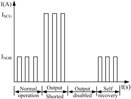
Fig.8 PWM operation with self-recovery software strategy[10]
Commonly available intelligent HSS has a single analog status output.BTS5200 from Infineon [11],NCV84160 from the On Semiconductor [12]and VN7050AJ from the STM[13]are examples of such switches.The load current can be monitored in real time by the MicrocontrollerUnit(MCU),monitoring the feedback current.The output is deactivated when the drive currentofintelligentHSS reaches the overcurrent protection threshold,as shown in Fig.9.The deactivate output can be activated again toggling the input command.And the protection strategy is the same as the SCG protection strategy,except the length of the disabled time.

Fig.9 Overload current peaks in PWM operation[10]
3.3 Load-Dump Transient Over-Voltage Protec⁃tion
The load-dump transient over-voltage phenomenon among all transient over-voltage phenomenon in the vehicle's power supply environment is the most harmful to the ECU(Electronic Control Unit).In order to protect the ECU,Transient Voltage Suppressor(TVS)is usually used for voltage suppression[14],as shown in Fig.10.TVS selection involves comparison of device parameters with circuit conditions[15].The following selection guidelines are recommended:
i.Select a TVS with a reverse standoff voltage greater than or equal to the normal operating voltage of the circuit.
ii.The TVS clamping voltage should be less than the maximum voltage handling capability of the protected circuit for the same pulse waveform.
iii.Select a TVS which is capable of dissipating the expected transient peak pulse current.

Fig.10 TVS transient overvoltage protection circuit[14]
The maximum clamping voltage of TVS is mainly determined by its on-current,which is determined by the testvoltagepulseparameters.DifferentOEMshave different requirements on the test voltage pulse parameters,so the maximum voltage of the ECU power input is different.In order to accurately control the maximum voltage of the ECU,a load-dump transient overvoltage suppression circuit is proposed,as shown in Fig.11.The PMOS in series with power supply input path is switched off when the input supply voltage is higher than threshold voltage VTH+,as well the PMOS is switched on when the input supply voltage is lower than VTH-.The maximum voltage of the ECU input power supply can be precisely controlled since threshold voltage VTH+can be set precisely.

Fig.11 Load-dump transient overvoltage suppression circuit
4 DIAGNOSTIC AND AN IM⁃PROVED DIAGNOSTIC STRATEGY FORINTELLIGENTHSS
Here is a concept which provides improved diagnostic features,making use of discrete HSS having the digital status signal.Faults like SCG,SCB and OL can happen when the HSS is in off-state or on-state.In order to avoid system failure and protect the intelligent HSS,it is necessary to diagnose SCB and OL when the intelligent HSS switches off and diagnose SCG when the intelligent HSS switches on[16-17].The intelligent HSS typically outputs status via ST pin,whose logic low indicates the fault status for all kinds of faults such as SCB,SCG and OL[18-20].The output of ST has two properties.On the one hand,it provides a logic low signal for SCG fault during the HSS switching on.On the other hand,it provides a logic low signal for SCB fault and OL fault during the HSS switching off.However,the ST signal cannot distinguish SCB and OL[21],shown as Table 3.
In order to detect and distinguish various fault types,an intelligent HSS fault diagnosis strategy is proposed in this chapter,which takes precise control measures at the system level,the fault diagnosis circuit is shown in Fig.12.An analog feedback circuit is added to the output port of the intelligent HSS to distinguish the fault type by detecting the voltage value of output port for the intelligent HSS.

Fig.12 Schematic representation of the intelligent HSS and diagnosis network
Assuming that the system is 12 V DC system,whose voltage ranges from 6 V to 16 V,tolerance of the internal 5 V power supply is 2%,minimum load resistance RLOADis 5 Ω,and resistance tolerance is 3%.The ADC values can be calculated by considering the front application parameters,shown as Table 4.
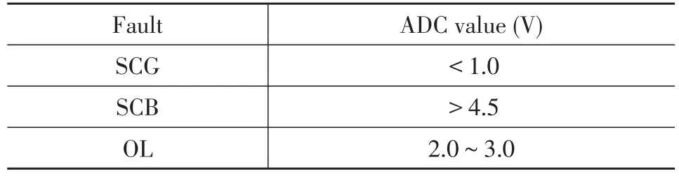
Table 4. Diagnostics with digital status signal to detect faults
The SCG is detected during the switch-on state of the intelligent HSS,while the SCB and OL are detected during the switch-off state of the intelligent HSS.The intelligent HSS is immediately switched off to protect the intelligent HSS when the MCU detects a fault.Fault detections and proper distinction of each fault are depicted in a flowchart,shown as Fig.13.

Fig.13 Flowchart for the diagnostic strategy of the intelligent HSS
5 SWITCHING INDUCTIVE LOADS AND EXTERNAL CLAMPING
5.1 The Process of Intelligent HSS Switch-on and Switch-off
In automotive electronic control systems,intelligent HSS is widely used to control inductive loads such as relays,solenoids,motors,etc.When an inductive load is switched on,the current increases within a time constant τ,given by L/R,instead ofimmediately reaching the maximum value,When the inductive load is switched off,the current continues to flow in the same direction due to the inductance,resulting in a reverse load voltage VDEMAG,which is determined by the clamping voltage VCLAMPof the HSS and the battery voltage VBAT:

The load current decays exponentially(linearly if R→0)and reaches zero when all energy stored in the inductor is dissipated through the HSS and the load resistance.The process of intelligent HSS switch-on and switch-off is shown in Fig.14.

Fig.14 The process of intelligent HSS switch-on and switchoff[8]
The energy dissipated in the HSS is given by the integral of the actual power on the MOSFET through the demagnetization time:

The iOUT(t)can be obtained from the current response formula of the R/L circuit using the initial current I0and the final current VDEMAG/R.
Where,iOUT(0)is the initial value of iOUT(t),RLOADis the load resistance.The demagnetization time TDEMAGcan be calculated assuming iOUTis equal to 0:
The energy dissipated in the HSS can be calculate by substituting equations(3)and(4)into equation(2):
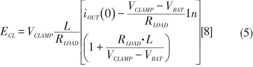
The sensitivity analysis is performed on equation(5),and the results are as follows:
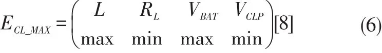
The maximum clamping energy is obtained on the conditions of the low temperature environment,the lowest load resistance,the highest supply voltage,and the lowest clamping voltage.In order to avoid the breakdown of the intelligent HSS,the rated energy EARhas to be above ECL_MAX.
5.2 The Damage Analysis and Selection of the Intelligent HSS
Even if the device is internally protected against break down during the demagnetization phase,the clamping capability should be taken into account during the design of the application.Two main mechanisms that lead to a device failure are summarized.
i.The temperature during the demagnetization rises quickly and the uneven energy distribution on the power surface can lead to the device failure with a single shot.
ii.As in normal operations,the life time of the device is affected by the fast thermal variation as described by the Coffin-Manson law [22-23].Temperature variations caused by repetitive demagnetization energy shorten the life time.
Therefore,two simple design rules are required as follows:the energy has to be below the energy the device can withstand at a given inductance,and in case of a repetitive pulse the average temperature variation of the device should not exceed 60℃at switch-off state.In order to meet these rules,the energy dissipated of the intelligent HSS at switch-off state must be calculated and then compared with the data sheet values.
5.3 External Clamping Selection
The main function of the external clamping circuit is to clamp the demagnetization voltage and dissipate the demagnetization energy to protect the intelligent HSS.It is a cost effective alternative in case the demagnetization energy exceeds the energy capability of a given HSS.The requirements of the externalclamping circuit are summarized as follows:
i.Proper negative clamping voltage to protect the intelligent HSS.
ii.The external clamping circuit is in the off-state in the ECU operating voltage range(0 to 16 V),the reverse power supply(-14 V@5 min),and the load dump(40 V@600 ms).The consumed current can be negligible;
iii. Proper energy capability to meet single demagnetization pulse and repetitive demagnetization pulse.
Based on the above theoretical analysis and summary,proposes three external clamping circuits are proposed in this chapter.
External clamping with freewheeling diode is shown in Fig.15.A diode parallel connected with the load provides a demagnetization path,and a relatively low demagnetization voltage(that is the diode forward voltage drop)results in a very slow demagnetization.However,it has a negative influence on the actuator.For example,when the relay is controlled,the armature moves slowly leading the relay contacts slowly disconnected,which will reduce the lifetime of the relay contacts.
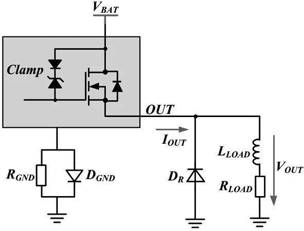
Fig.15 External clamping with freewheeling diode
External clamping with freewheeling diode and TVS is shown in Fig.16.The demagnetization voltage is lifted by the TVS series connected with diode.This diode is necessary to decouple the TVS during normal operation.The main advantage of this circuit is that the higher demagnetization voltage makes inductive loads faster demagnetize compared to freewheeling diode clamping circuit.Therefore it is important to select an appropriate TVS,which must ensure that the voltage across the intelligent HSS is lower than the minimum clamping voltage specified in its data sheet.

Fig.16 External clamping with freewheeling diode and TVS
External clamping with parallel connecting TVS is shown in Fig.17.The main advantage of this circuit is also thatthe higherdemagnetization voltage causes the inductive load to demagnetize faster.The clamping voltage of the TVS should be below the minimum clamping voltage of the intelligent HSS.However,the external clamping circuit should be prevented from being switched on(TVS is activated)during load dump pulse.Because there is a high probability that it is damaged(overheated)by current flow through the load once the TVS is activated during the loaddump pulse.The appropriate external clamping circuit should be selected depending on the application.
6 CONCLUSION
In this paper,electromechanical relays,intelligent HSS and intelligent LSS are compared and analyzed in terms of reliability,short-circuit hazard,system cost and galvanic corrosion.The possible problems of applying intelligent HSS in automotive electronic systems are analyzed and summarized,while the corresponding solutions are proposed.The above methods have been verified and validated in the laboratory and real vehicle.All the intelligent HSS applications detailed here are completely feasible and cost-effective compared with electromechanical relays solutions.Most of them are already running or going to be applied on vehicles.
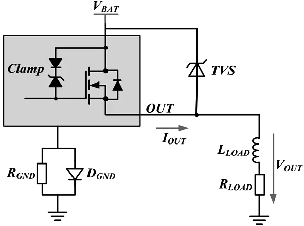
Fig.17 External clamping with parallel connecting TVS
With the rapid developmentofsemiconductor technology,especially semiconductor power devices based on Silicon Carbide(SiC),new improvements will reduce the on-resistance and thermal resistance between junction to ambient,etc.The intelligent HSS will also play an increasingly important role in increasing energy efficiency,fuel economy,miniaturization of electrical systems and reducing the cost of electrical content in vehicles.A new chapter will come in the history of automotive semiconductor power devices.
猜你喜欢
中国交通信息化(2022年9期)2022-11-19
汽车工程师(2021年12期)2022-01-18
汽车工程师(2021年11期)2021-12-21
科学与财富(2021年35期)2021-05-10
汽车维修与保养(2021年8期)2021-02-16
汽车生活(2018年5期)2018-06-21
档案管理(2014年6期)2014-10-30
商品与质量·消费研究(2013年7期)2013-08-29
城市建设理论研究(2011年28期)2011-12-31