Simulation of the influence of imperfections on dynamical decoupling of a superconducting qubit∗
Ying-Shan Zhang(张颖珊),Jian-She Liu(刘建设),Chang-Hao Zhao(赵昌昊),Yong-Cheng He(何永成),Da Xu(徐达),and Wei Chen(陈炜)
1Department of Microelectronics and Nanoelectronics,Tsinghua University,Beijing 100084,China
2Institute of Microelectronics,Tsinghua University,Beijing 100084,China
3Tsinghua National Laboratory for Information Science and Technology,Tsinghua University,Beijing 100084,China
Keywords:dynamical decoupling,superconducting qubit,imperfection,dephasing
1.Introduction
A superconducting quantum system is one of the most promising candidates for practical quantum computers.Considerable efforts have been made to integrate the wide variety of superconducting qubits and their auxiliary equipment.However,scaling up while maintaining relatively long coherence time is still dif ficult.Decoherence induces errors in computing.Speci fically,relaxation causes bit- flip error and dephasing leads to phase- flip error.If we wish to run useful algorithms on such a vulnerable superconducting quantum computer,then errors have to be compensated for.One way to do this is quantum error correction(QEC),[1,2]where one actively detects errors and then corrects them.Another way is error mitigation,in which dynamical decoupling(DD)and decoherence-free subspaces(DFSs)are prominent.[3-5]Compared to QEC and DFSs,DD consumes much less time and hardware resources because of no encoding overhead and is more suitable for current superconducting quantum systems with a few dozens of noisy qubits.[6,7]In an advanced quantumsystem with many qubits that reach fault-tolerant threshold,we can even combine unconditional DD with conditional QEC to achieve a balance between performance and overhead.[8]DD can prolong quantum state storage time and be flexibly inserted into quantum circuits to improve fidelity of quantum state manipulation.[9]It is also scalable because we can perform DD on each qubit independently and simultaneously in multi-qubit systems.[10,11]
Dynamic decoupling has been utilized in superconducting quantum systems to protect the Bell state,[12]and the entanglement between a qubit and a microscopic two-level system.[13]Dynamic decoupling has also been applied to aflux qubit[14]and a transmon qubit[15]as a probe for noise spectroscopy.Nevertheless,imperfections can result in lowered or even lost effectiveness of DD.[16]Imperfections relevant to the efficiency of DD against dephasing originate from erroneous generation of DD signal,distortion of the signal due to circuit components,and qubit relaxation.To the best of our knowledge,the effects of imperfections on the performance of DD on superconducting qubits have not yet been systematically discussed.
In the present paper,we study the impact of such imperfections on the results of DD via simulations.The rest of this paper is organized as follows.We first describe the theoretical model of a qubit,its noise environment and driving pulses,and we then conduct master equation simulation of the qubit evolution.By comparing the performance of DD under distinctive imperfections,we finally discuss what imperfections count and how to avoid their adverse effects.
2.Theoretical model
2.1.Qubit dynamics
A qubit state can be expressed as density matrix ρ.The qubit’s evolution follows Liouville-Von Neumann equation[17]

where i is the imaginary unit,¯h is the reduced Planck constant,and H is the qubit Hamiltonian

ωqis the qubit transition frequency.σzisPauli Z-matrix.Hc(t)is the time-dependent control signal,and Hn(t)is the noise.For a classical noise that leads to dephasing[18]

where n(t)is a random function of time.
An alternative way to express noise is power spectral density.Low-frequency noise causes dephasing,while highfrequency noise close to positive(negative)qubit frequency leads to relaxation(excitation)(see Appendix A for more detailed discussions).In superconducting quantum circuits,low frequency noise is well approximated by 1/f noise.[19]Therefore,we use 1/f noise to study dephasing.In other words,n(t)has 1/f power spectrum.
The environment consists of multiple channels of qubit decoherence.The dynamics of qubit in environment follows Lindblad master equation[20]

where H is the qubit Hamiltonian that represents coherent evolution and Lkis the collapse operator of the k-th decoherence channel.Assuming constant relaxation rate γ1,then the expressions for relaxation and excitation are

where nthis the residual thermal population of qubit.
2.2.DD and relevant imperfections
Dynamic decoupling is the application of control sequences designed against unwanted system-environment coupling,denoted by a Hamiltonian HSE.The control Hamiltonian Hc(t)on the system has propagator[21]

where T is the time-ordering operator. Under the frame change with unitary operatorUc(t),HSEbecomes

where˙Uc(t)is the time derivative ofUc(t).The propagator for the controlled system is[22]

For N-order decoupling with cyclic controlUc(t+Tc)=Uc(t)of period Tc,the expansion of U(nTc)in Tcto the N-th order shows no effect on the system,for any natural number n.That is,if we stroboscopically observe the system at the end of each control cycle,then the system is effectively decoupled from the environment to the N-th order.For decoupling sequences to work,the noise in a control cycle should be correlated in some way.1/f noise is coherent noise and has quite a long correlation time,which makes it perfect for the demonstration of DD.
The basic DD protocols are Carr-Purcell(CP)[23]and Carr-Purcell-Meiboom-Gill(CPMG)[24],which are composed of evenly-spaced π-pulses.The initial qubit state and the rotation axes of control pulses are all in the XY plane,but the rotation axis of CP π-pulses is perpendicular to qubit initial state while that of CPMG is parallel to it.CPMG is theoretically better than CP because state error accumulates only in the fourth order of pulse nutation error for CPMG,while in the second order for CP.[25]
The Uhrig DD(UDD)[26]protocol has the same rotation axis as CPMG but the k-th π-pulse is applied at

where tDDis the total evolution time and NDDis the total number of decoupling pulses.For noise with a power density spectrum that increases with frequency and suddenly cuts off,UDD works better than CPMG.[27]But for most noise types that diminish with frequency,CPMG is the better choice.
The measurement system for DD in a three-dimensional(3D)superconducting transmon qubit studied in this work is presented in Fig.1.For other superconducting qubit types,the input ports for driving and measurement pulses may be separate.However,places where error can occur are basically the same,as demonstrated in the light gray dashed boxes in Fig.1.First,low-frequency pulses are generated by an arbitrary waveform generator(AWG)to control the timing of driving and measurement pulses.Driving pulses have two channels that control qubit rotations in the XY plane.CP,CPMG,and UDD pulses are originally written in Dirac δ function,assuming each pulse to be in finitely strong and fast.This control protocol is called bang-bang control.But in practice,superconducting qubits are controlled by bounded pulses,with limited height and width,which is an inevitable source of error.Also,AWG has jitter errors.Consequently,the width and position of a pulse can deviate from its assigned value.Then,an IQ mixer takes the two-channel control pulses from AWG and mixes them with continuous high-frequency signal from a microwave source.Ideally,when the control pulses are zero in both channels,the output signal from the mixer should also be zero.However,the on-off ratio of the mixer is finite and the output is not completely turned off.This composes another source of imperfection.Next,the mixed signal goes through a splitter to combine it with measurement signal,attenuators to minimize thermal noise,a filter to exclude highfrequency noise and multiple wiring coaxial cables,before it reaches qubit cavity.The nonlinearity of these components and impedance mismatch at their interfaces can all contribute to the distortion of driving signal seen by the qubit,which is named as filtering effect.Finally,the superconducting qubit itself has finite relaxation time and can randomly jump between its two eigenstates during DD against dephasing,which may affect the measurement results.
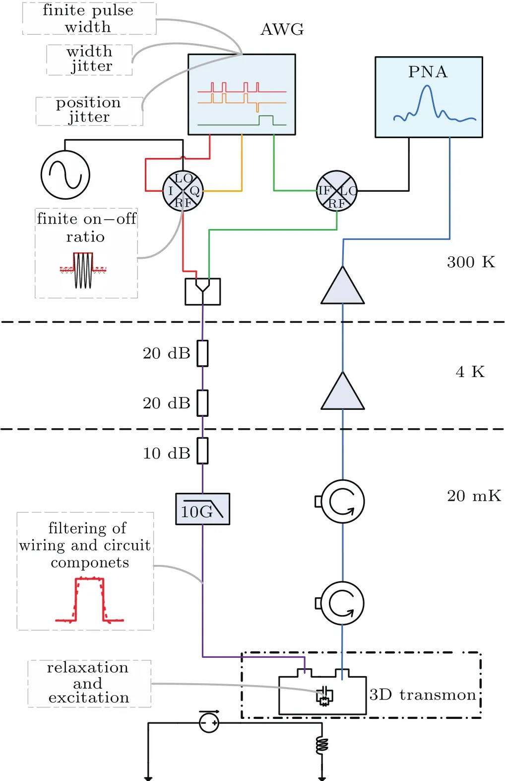
Fig.1.The DD measurement system for a 3D superconducting transmon qubit.Imperfections aredescribed,some with schematic diagrams,in light-gray dashed boxes.
3.Method
QuTiP[28]is a useful toolbox for numerical simulation in quantum systems. It provides master equation solver brmesolve(·)that allows us to specify the noise power spectrum,but its Hamiltonian has to be time-independent.Another solver in QuTiP,mesolve(·),is capable of dealing with time-dependent Hamiltonian and collapse operators but does not include noise power spectrum.To simulate a qubit under DD pulses with 1/f noise,we put 1/f noise into the Hamiltonian,as shown in Eq.(3),and we utilize mesolve(·)to address the problem.

Fig.2.Simulation of qubit evolution under CP decoupling pulses.(a)Above are qubit control(blue)and measurement(green)pulses for NDD=1 with 1/f noise(purple).Below is the corresponding qubit evolution on Bloch sphere.Left to right:initial|0〉state,dephasing during the first tDD/2,decoupling during the second tDD/2, final state deviated from|0〉because of dephasing;(b)Qubit evolution with time for different NDDand corresponding linear fitting curves.Each point is an average of 100 times of simulation.
As can be seen in Fig.2(a),in experiments of DD on a superconducting qubit,we first rotate the qubit to XY plane by an X(π/2)pulse,then perform X(π)or Y(π)DD pulses for NDDtimes with intervals de fined in Subsection 2.2.At last,the qubit is rotated back for measurement by an X(π/2)or-X(π/2)compensation pulse,which ensures that the total rotation angle of all control pulses is an integer multiple of 2π.
In our simulation,for each NDDand tDD,we generate a time-domain sequence of 1/f noise(see Appendix B)and add it to the same control Hamiltonian as in experiments.Starting from the initial density matrix|0〉〈0|,we calculate mesolve(·)for one time step and update the density matrix.The stepwise calculation is repeated until the density matrix of the final state is recorded.This procedure is repeated for 100 times and the final density matrices are averaged.Finally,the expectation value of σzis evaluated for the averaged density matrix.We sweep tDDto achieve the average time evolution ofand sweep NDDfrom 1 to 10.An example of the results is shown in Fig.2(b).Then the slope of time evolution is extracted as the average dephasing ratewhich is a good indication of DD performance.A large〉means fast dephasing and bad performance of decoupling.
Without DD,we adjust the qubit dephasing time to T2∼200ns by modifying the strength of 1/f noise.For the moment,we use rectangular pulses.TRabi=40ns is chosen as the Rabi oscillation period.A short TRabiis preferable,but the minimal TRabiavailable is limited by the precision of AWG.For an ordinary measurement system,the maximum sample rate of AWG is around 109sample/s,which makes TRabi=40ns a practical choice.The length of a π pulse is TRabi/2=20ns,for both X-control and Y-control.The preparation and compensation pulses are 10ns long each,a quarter of TRabi.
4.Results and discussion
We now present the simulation results and compare the influence of the imperfections listed in Fig.1.We will then brie fly discuss the ways to fight against imperfections that have signi ficant effects on the performance of DD.
4.1.Qubit relaxation
We begin our analysis with the effect of limited qubit relaxation time.We simulate bounded CP on a noisy qubit with T1=1/(2γ1)=560ns,along with a good qubit with T1=10µs,and compare them to an ideal qubit with no relaxation.Figure 3 elucidates that longer T1has little improvement on the performance of DD.In our following discussions,we can safely assume T1=∞when simulating the effects of other factors.

Fig.3.Bounded CP decoupling results for qubits with T1=560ns,and T1=10µs,and in finite T1.
4.2.Bounded pulses
Now we compare the performance of ideal pulses with bounded ones.The impacts of finite pulse width on different decoupling protocols are shown in Fig.4.As NDDincreases,the interval between adjacent pulses decreases for a fixed tDD.Therefore,the effect of decoupling improves with NDD,for both ideal and bounded cases.Bounded pulses deteriorate the performance of all three DD protocols,indicated by higherthan their ideal counterparts.The differences become more obvious for bigger NDD.Ideal CP and CPMG are almost as good but CPMG works better when bounded because it is more robust to error.UDD has poor performance,even in ideal case,because it essentially is designed for highfrequency noise.

Fig.4.(a)Waveform of ideal(blue dotted line)and bounded(red solid line)CP,CPMG,and UDD for NDD=5;(b)Comparison between CP,CPMG,and UDD pulses with ideal and bounded strength.Error bar is linear fitting error(not simulation error).
4.3.Jitter
From now on,we concentrate on the bounded CP because it is more prone to error than CPMG and more sensitive to 1/f noise than UDD.In other words,it epitomizes more clearly the influence of imperfections.We then consider the jitter of AWG.Jitter is modeled with the truncated normal distribution between±0.25ns with meanµ=0ns and standard deviation σ=0.1ns.We add this random jitter to the position or width of each CP pulse and the simulation results are illustrated in Fig.5.The jitter in pulse width causes a slight reduction in performance of CP,while the jitter in pulse position significantly increases〉and is obviously detrimental to the performance because the error caused by positive and minus jitter in pulse width can counteract to a large extent,while the error due to the jitter in position cannot.Hence,the jitter in pulse position should be carefully treated if we want to suppress the dephasing.
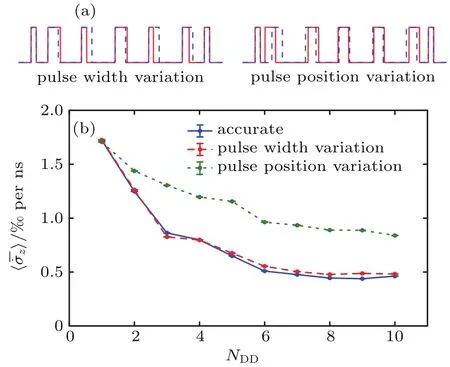
Fig.5.(a)Waveform of bounded CP with jitter for NDD=5.The bluedotted line is the accurate waveform,while the red-solid line contains jitter in pulse width(left)or position(right).The extent of jitter is exaggerated for clarity;(b)Impact of jitter in position or width on the performance of bounded CP pulses.
4.4.Finite on-off ratio
The finiteon-offratioofmixerismodeledas10%residue when its input is zero.Equivalently,the LO to RF isolation of the mixer is 20dB.In Fig.6,we plot the average trajectories for different NDD.These trajectories deviate greatly from ideal ones in Fig.2(b)so that they can no longer be fitted linearly.The oscillation of state in time is apparently due to qubit rotation by the residual drive when control should be turned off.Consequently,the dynamic decoupling cannot work properly if the on-off ratio of mixer is not good enough.

Fig.6.Qubit average trajectories with bounded CP when mixer output cannot be completely turned off.
4.5.Filtering effect
Filtering effect is another inevitable source of error.We use a low-pass Butterworth Filter(BF)to emulate the filtering of circuit components.The order of the filter is 1 or 3,and the-3dB bandwidth is 0.2 or 0.4 times Nyquist frequency fc.From Fig.7,we can see that different filtering parameters produce similar effects,despite the fact that the waveforms after filtering are different.The performance with filter is much worse than that without them.Thus filtering effect is a signi ficant factor that may make DD fail.
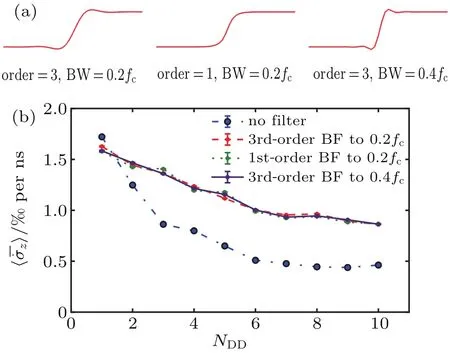
Fig.7.(a)Waveform of bounded CP after passing through a Butterworth Filter(BF)with different order and bandwidth parameters;(b)Bounded CP decoupling results for un filtered and filtered pulses.
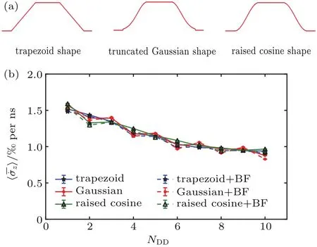
Fig.8.(a)The shape of trapezoid,truncated Gaussian,and raised cosine pulse;(b)Bounded CP decoupling results using the above pulses,with and without filtering effect.
We sometimes engineer the pulse shape to achieve better gate fidelity.The steep rising and falling edges of a rectangular pulse have in finite high-frequency components,which bring about distortion when the pulse encounters filtering.We change the shape of edges to mitigate such deformation.Trapezoid,truncated Gaussian and raised cosine types of pulse shapes are simulated here,as shown in Fig.8(a),in which raised cosine is theoretically the best because of its smooth transitions.[29]When we use these three pulse types instead of rectangular pulse,the performance before and after filtering are summarized in Fig.8(b).The filtering effect is modeled by a 3rd-order BF with 0.01fcbandwidth.The rising and falling time for all three pulse types are 10ns.For truncated Gaussian shape,we use σ =5ns,and truncate to 2σ.The waveforms before and after the pulses pass through the filter are nearly identical,even for the narrow bandwidth we choose.Performanceof CP with and without filtering for these pulses are also almost the same,which implies that filtering no longer adds to error with optimized pulse shaping.However,because the shaped pulses in our simulation share the same pulse height as rectangular pulses,they are much wider and suffer more from dephasing within pulse duration.Thus their performance are inferior to perfect rectangular pulses and approaches that of filtered rectangular pulses,as shown by the blue dash-dot and red-dashed lines in Fig.7,respectively.Pulse shaping can eliminate the error caused by filtering effect,but does not necessarily assist DD to perform better.As a matter of fact,when the qubit itself has short dephasing time,we need shorter pulses with larger height if we want to improve DD performance by pulse shaping.
4.6.Solutions
The impacts of all imperfections discussed in this paper and corresponding countermeasures are summarized in Table 1.

Table 1.Types of imperfections,the severity of their effects on DD and how to alleviate these effects.
More complicated DD protocols are favorable as far as bounded pulses are concerned. For example,Eulerian DD[22,30]eliminates the effect of bounded pulses and concatenated DD[31]features higher-order robust decoupling of qubits against dephasing as well as relaxation.Pulse position jitter can be mitigated by synchronizing the AWG and the microwave source with a 10MHz clock standard,reducing rounding errors with carefully chosen parameters or highprecision AWG,and avoiding mechanical vibrations of devices and wiring.As experimental results in our lab indicate,if the LO to RF isolation of the mixer is less than 80dB,corresponding to an on-off ratio of 10000:1,residual drive will lead to visible degradation.Therefore,we usually cascade two or three mixers with 20 dB-40 dB isolation each to avoid this problem.Pulse shapes with gradual transition edges are robust to the filtering effect.The simulations and analysis of imperfections can be further generalized to other applications of DD,such as the improvement of sensitivity of quantum sensing with NV centers.[32]
5.Conclusion
In this paper,we have built a model of a superconducting qubit under 1/f noise and DD driving pulses.We use QuTiP to simulate qubit evolution and compare the performance of DD via average dephasing rate under the influence of various imperfections.Bounded pulses perform worse than ideal ones.Jitter in pulse position,poor on-off ratio and filtering effect can greatly degrade DD performance,while jitter in pulse width and qubit relaxation has smaller effects.Pulse shaping can prevent the pulses from distortion by filtering effect,but short pulses are necessary to improve DD performance.These methods and some of the conclusions in this work can be applied to more complicated systems,such as quantum information processing system with multiple superconducting qubits.
Appendix A:Understanding relaxation and dephasing
The interaction between a qubit and a harmonic oscillation mode from its environment is described by the Jaynes-Cummings Hamiltonian:

ωqand ωaare the resonant frequency of the qubit and the oscillation mode,respectively.is Pauli Z-matrix.a and a†are annihilation and creation operator of the mode.is the lowering operator that destroys an exciton and changes qubit state from|1〉to|0〉,while its conjugate transposeis the raising operator that creates an exciton and transforms|0〉to|1〉.g is the coupling strength between the qubit and the mode.We denote Δ = ωq-ωaas the frequency difference between the qubit and the mode.When Δ≫g,which is the so-called weak coupling regime,there is no direct energy exchange because of energy conservation.But qubit energy levels are slightly modi fied by the number of excitons in the mode.Accordingly,the fluctuations in exciton number result in spectral broadening.Spectral broadening can be regarded as uncertain rotation velocity around Z axis on Bloch sphere.Hence,dephasing occurs,which means that the phase of the qubit state becomes randomized.Meanwhile,Δ≪g is a strong coupling regime.The qubit can absorb a photon from the mode and experience a transition from|0〉to|1〉,which is excitation.It can also emit a photon to the mode and undergo a transition|1〉to|0〉,which is relaxation.When Δ∼g,dephasing,excitation and relaxation can happen at the same time.For a superconducting qubit of a few GHz resonant frequency,its coupling with low-frequency modes from its environment are the source of dephasing,while high-frequency modes contribute to excitation and relaxation.
Appendix B:Generation of 111/// fff noise in time domain
We denote the power spectral density of random noise n(t)as Snn(f).They are connected by z(f),the Fourier trans-
form of n(t):

For the purpose of simulation,a discrete-time version of n(t)has to be generated from Snn(f)repeatedly.We assume Snn(f)can be truncated,namely:when f>fcut,Snn(f)=0.This is a good approximation for most noise types,such as 1/f noise.According to the Nyquist theorem,let Δt=1/(2fmax)be the time step of our length-N sequence nseq,where fmax≥fcut,then we should also sample N points from Snn(f).Note that a practical power spectral density is symmetric,Snn(f)=Snn(-f),so we can choose M=N/2+1 sampling points for f≥0.The sampled sequence is de fined as Sseq={Snn(-(M-2)Δf),Snn(-(M-3)Δf),...,Snn(-Δf),Snn(0),Snn(Δf),...,Snn((M-2)Δf),Snn((M-1)Δf)}.The interval between adjacent points in Sseqis Δf=fmax/(M-1).We also de fine zseq={z(-(M-2)Δf),z(-(M-3)Δf),...,z(-Δf),z(0),z(Δf),...,z((M-2)Δ f),z((M-1)Δ f)}as the fast Fourier transform(FFT)ofnseq.WhenwecalculatezseqfromSseq,arbitrary phases are added to recover randomness because Sseqdoes not contain phase information.We generate phases that obey uniform distribution in[0,2π),φ(j),j=1,2,...,M-2.Let D=fcut/Δf,then

z(0)may not be convergent for some noise spectrums such as 1/f noise,so we substitute it with an independent DC component z0.Finally,we use inverse FFT(iFFT)to get nseq:

where Re(·)takesthe real part of a complex number.
Acknowledgment
The authors thank Liu Yulong from Tsinghua University and Wang Xin from Xi’an Jiaotong University for helpful discussions on QuTiP.
- Chinese Physics B的其它文章
- Topological superconductivity in a Bi2Te3/NbSe2heterostructure:A review∗
- The universal characteristic water content of aqueous solutions∗
- Neutral excitation and bulk gap of fractional quantum Hall liquids in disk geometry∗
- Direct deposition of graphene nanowalls on ceramic powders for the fabrication of a ceramic matrix composite∗
- Hard carbons derived from pine nut shells as anode materials for Na-ion batteries∗
- Crystal structures and sign reversal Hall resistivities in iron-based superconductors Lix(C3H10N2)0.32FeSe(0.15<x<0.4)∗

