
influence of carbon coating on the electrochemical performance of SiO@C/graphite composite anode materials∗
2019-06-18 05:42HaoLu陆浩JunyangWang汪君洋BonanLiu刘柏男GengChu褚赓GeZhou周格FeiLuo罗飞JieyunZheng郑杰允XiqianYu禹习谦andHongLi李泓
Chinese Physics B 2019年6期
Hao Lu(陆浩),Junyang Wang(汪君洋),Bonan Liu(刘柏男),Geng Chu(褚赓),Ge Zhou(周格),Fei Luo(罗飞),Jieyun Zheng(郑杰允),Xiqian Yu(禹习谦),‡,and Hong Li(李泓),†
1Beijing National Laboratory for Condensed Matter Physics,Institute of Physics,Chinese Academy of Sciences,Beijing 100190,China
2School of Physical Sciences,University of Chinese Academy of Sciences(CAS),Beijing 100049,China
3CAS Research Group on High Energy Density Lithium Batteries for EV,Institute of Chemistry,Chinese Academy of Sciences,Beijing 100190,China
4Key Laboratory of Green Process Engineering,State Key Laboratory of Multiphase Complex Systems,Institute of Process Engineering,Chinese Academy of Sciences,Beijing 100190,China
5Tianmulake Excellent Anode Materials Co.,Ltd.,Changzhou 213300,China
Keywords:lithium-ion battery,silicon monoxide,carbon coating,anode material
1.Introduction
Rechargeable lithium-ion batteries(LIBs)have been widely applied as predominant power sources in portable electronic devices,electric vehicles(EV),and electricity storage systems.With the rapid development of emerging electric vehicle markets,the increasing demands for high energy and power density,long-term cyclic stability,and low-cost have been critical challenges for lithium-ion batteries.[1-3]Among all the anode materials for LIBs that have been developed until now,silicon(Si)is considered as the most promising anode material for next generation high-energy-density LIBs owing to its high specific capacity(∼ 4200 mAh·g-1)and low operating voltage for Li+insertion/extraction(<0.5 V versus Li+/Li).[4,5]However,there are two major drawbacks for the Si anode that hinder its commercial application:(i)the low intrinsic electric conductivity,and(ii)the severe volume swelling(>400%)during repeated Li-Si alloying/dealloying process.The drastic volume change leads to severe pulverization of the electrode,continuous formation of unstable solid electrolyte interphase(SEI)over recurrent charge/discharge cycles,and thus rapid decay of specific capacity.[6,7]Many strategies-such as employing nanocrystallized Si,forming composites with other phases,and surface coating with carbon-have been applied to achieve better electrochemical performance of Si anodes.[8-14]However,the long-term cycling stability of Si anode materials is still not yet able to meet the strict requirements for practical applications.
As an alternative material among the Si-based anode materials,silicon monoxide(SiO)has been attracting growing attention in recent years because of its high reversible specific capacity(∼ 2400 mAh·g-1)and stable cycling performance.The structural model of amorphous SiO is still ambiguous,with amorphous Si and SiO2clusters surrounded by Si-suboxide matrix as one plausible model.[15-17]This unique microstructure of SiO can effectively alleviate the large volume change of SiO electrodes during cycling,comparing with Si anodes.More speci fically,during the first lithiation pro-cess,Li reacts with SiO2to produce Li2O and LixSiOy(mainly Li4SiO4).Such compounds can act as buffer skeleton and relieve the severe volume change of SiO electrodes caused by further lithiation reaction,reducing the pulverization of SiO electrodes and the electrical disconnection with current collectors,and thus improve the cyclic performance of SiO.
Nevertheless,SiO anode materials still suffer from relatively large volume change(∼200%)during Li+insertion/extraction and low initial coulombic efficiency(ICE),due to the poor intrinsic electrical conductivity and the irreversible reactionbetweenLi+andSiO2clusters.Toresolvetheseproblems,several methods including element doping(e.g.,boron,titanium,and tungsten),construction of SiO/C composites,and surface coating(e.g.,carbon,TiO2,and Fe3O4)have been conducted to further improve the performance of SiO.[18-24]Among these strategies,surface coating with carbonaceous materials(e.g.,graphite,amorphous carbon,carbon nano fiber,carbon nanotubes,graphene,and reduced graphene oxide)has been widely employed in industrial production due to its lowcost and remarkable improvements in performance.For example,Wang et al.synthesized a carbon coated SiO nanocomposite with a core-shell structure via a solution route,which exhibits a high reversible specific capacity of∼ 800 mAh·g-1at the 50th cycle and excellent rate performance.[25]Lee et al.reported that a nitrogen-doped carbon coated micro-sized SiO anode delivers a reversible capacity of 955 mAh·g-1after 200 cycles at a current density of 1500 mA·g-1,whereas only 545 mAh·g-1for bare SiO.[26]Carbon coating on SiO surface can greatly improve the electrical conductivity,effectively reduce the polarization,and relieve the severe volume change of SiO electrode,thus significantly enhance its cycling stability and rate capability.To achieve an excellent comprehensive performance,the carbon content in the surface coating layers needs to be further controlled to maintain the high capacity,initial coulombic efficiency,and cycle stability.
In this work,the micro-sized SiO@C with carbon coating layer of different thicknesses were controllably synthesized via a simple pitch pyrolysis reaction method.The effect of carbon content on the electrochemical performances of SiO@C was investigated.The SiO@C/graphite(SiO@C/G)composites with the target capacity of 600 mAh·g-1were further synthesized by a ball-milling process.The SiO@C/G composite anodes exhibit a high reversible capacity and improved cycling performance in half cells as well as full cells with LiNi0.5Co0.2Mn0.3O2(NCM)as cathode material.
2.Experiment
2.1.Fabrication of SiO@C/G composites
Silicon monoxide(Tianmulake Excellent Anode Materials Co.,Ltd.)was selected as the raw material to prepare the SiO@C composites via a simple pitch pyrolysis method.Firstly,SiO powder with an average particle size of 4µm-6µm was mixed with petroleum pitch,then the above mixture was heat-treated at a temperature of 300°C for 2 h and then 900°C for 2 h at a heating rate of 10°C·min-1in Ar atmosphere to obtain SiO@C composites.By the above process,SiO@C composites with different carbon coating contents(5 wt%,10 wt%,15 wt%,and 35 wt%)were synthesized at different mass ratios of SiO powders and petroleum pitch,which were labeled as SiO@C-5,SiO@C-10,SiO@C-15,and SiO@C-35,respectively.
SiO@C/G composites were prepared to match the capacity of the cathode material.Graphite(Tianmulake Excellent Anode Materials Co.,Ltd.)was added to maintain the total capacity of SiO@C/G at 600 mAh·g-1.These mixtures were ball-milled for 5 h to obtain the final SiO@C/G composite materials(labeled as SiO@C/G-5,SiO@C/G-10,SiO@C/G-15,and SiO@C/G-35).The amount of graphite of SiO@C/G-5,SiO@C/G-10,SiO@C/G-15,and SiO@C/G-35 is 75.6 wt%,73.8 wt%,71.0 wt%,and 63.6 wt%,respectively.
2.2.Characterizations
The phase purity of aforementioned composite materials was characterized by an x-ray diffractometer(D8 Bruker)with Cu Kα radiation in the 2θ range of 10°-80°.The morphologies were investigated by scanning electron microscope(SEM,Hitachi-S4800)and transmission electron microscopy(TEM,FEI Tecnai G2 F20).Raman spectra were obtained by a Raman spectrometer(JY-HR800)using a 532-nm laser as a light source.The content of carbon was analyzed by carbon and sulphur analyzer(Yronh,CS-320).The tap density was measured by tapping apparatus(BNST,FZS4-4B).The specific surface areas of SiO@C samples were measured with the Brunauere-Emmete-Teller(BET)method by nitrogen adsorption isotherms collected at 77 K(Quantachrome,NOVA4200e).
2.3.Electrochemical characterizations
To make the electrode,the active material,carbon black,and water-soluble binder were mixed in a weight ratio of 93:2:5 in distilled water.The binder consisted of sodium carboxymethyl cellulose(CMC)and water system styrene butadiene rubber emulsion(SBR)water solutions in a weight ratio of 2:3.The slurry was deposited on copper foil using a blade and dried at 80°C in vacuum for 10 h.The mass loading of active materials was about 5 mg·cm-2.
Coin-type cells were assembled in an argon- filled glovebox using Celgard 2500 as a separator,1-mol·L-1LiPF6in ethylene carbonate(EC)/diethyl carbonate(DEC)(1:1,v/v)as an electrolyte,and Li foil as a counter electrode.The charge/discharge tests were carried out using a Land battery test system(CT2001 A,Land)in a voltage range of 0.005 V-2.0 V at 0.1 A·g-1.Electrochemical impedance spectroscopy(EIS)was measured at anopen-circuit voltage inthe frequency range of 100 kHz and 10 mHz on an electrochemical station(CHI600E).
Full cell electrochemical performance was evaluated in 2.5-Ah pouch cells using LiNi0.5Co0.2Mn0.3O2as cathodes and SiO@C/G composites as anodes.Both cathode and anode electrodes were fabricated in a pilot line(Tianmulake Excellent Anode Materials Co.,Ltd.).The electrolyte solution was 1-mol·L-1LiPF6in EC:DEC:DMC(1:1:1 in volume ratio).The full cells were charged and discharged in the voltage range of 2.75 V-4.2 V at various C-rates(1 C=677 mA·g-1).
3.Results and discussion
The synthesis process for micro-sized SiO@C/G composites is schematically illustrated in Fig.1.The micro-sized SiO@C samples with carbon coating layer of different thicknesses are first synthesized through a simple pitch pyrolysis reaction method.Then,the as-prepared SiO@C samples are mixed with graphite powders via a mechanical milling process to obtain the SiO@C/G composites.The carbon content of SiO@C samples are analyzed by carbon and sulphur analyzer.The actual carbon content for SiO@C-5,SiO@C-10,SiO@C-15,and SiO@C-35 samples are 5.3%,9.8%,15.8%,and 35.1%,respectively,which are well consistent with the designed values.With the increase in carbon content,the tap densities and the specific surface areas of SiO@C samples remain almost unchanged(Table 1),indicating a similar particle size and surface morphology.
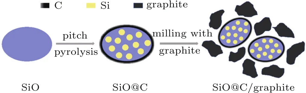
Fig.1.Schematic illustration of the preparation process of micro-sized SiO@C/G composites.

Table 1.The carbon content,tap density,and specific surface area of as-prepared SiO@C samples.
Phase composition and crystallinities of the pristine SiO and SiO@C samples are characterized by x-ray diffraction(XRD).For all diffraction patterns,as shown in Fig.2(a),they are composed of a hump and several relatively sharp diffraction peaks.The hump located in the 2θ range of 20°-30°is corresponding to a typical amorphous phase of SiO2,and the sharp diffraction peaks at 28.4°,47.3°,and 56.1°can be assigned to the crystalline phase of Si.The occurrence of the diffraction peaks of Si crystalline in the XRD patterns of SiO@C samples is due to a partial thermal disproportionation reaction of SiO during the pyrolysis process(Fig.1).The intensities of Si diffraction peaks are almost identical for all SiO@C samples,indicating that there is no signi ficant difference in Si content for all SiO@C samples.Figure 2(b)shows the Raman spectra of the as-prepared SiO@C samples.The peaks located at around 520 cm-1and 980 cm-1correspond to Si crystalline phase,which is in accordance with the XRD results.The peaks located at∼1340 cm-1and∼1575 cm-1correspond to the disordered(D)bands and graphene(G)bands of carbon,respectively,and the peak intensity ratio can be used to describe the extent of graphitization.The Raman spectra results demonstrate the existence of amorphous carbon(ID/IGratio is∼1.57)for the SiO@C samples.

Fig.2.(a)XRD patterns and(b)Raman spectra of the SiO@C samples.
SEM and high-resolution transmission electron microscopy(HRTEM)measurements are carried out to investigate the morphology and microstructure of the as-prepared SiO@C samples.As shown in Fig.3,the pristine SiO and as-prepared SiO@C samples have similar particle size with an average diameter of 4µm-6µm.The surface of SiO particles becomes smoother after carbon coating,contrasting the coarse surface of the pristine SiO particle(Figs.3(a)-3(f)).The uniform carbon coating is further con firmed by HRTEM.It can be clearly observed from Figs.3(g)-3(j)that the surface of SiO@C particles is uniformly coated by a dense amorphous carbon layer.With the increase in carbon content,the thickness of coating layer increases from 10.6 nm for SiO@C-5 to 23.8 nm,36.8 nm,and 81.0 nm for SiO@C-10,SiO@C-15,and SiO@C-35 samples,respectively.Such a dense carbon coating layer can enhance the electric conductivity of SiO electrode during lithium intercalation/de-intercalation,leading to the improvement of the electrochemical performance of SiO.
To evaluate the electrochemical performances of asprepared SiO@C samples,galvanostatic charge-discharge tests are performed by using a coin-type half-cell. Figure4(a)shows the charge/discharge voltage profiles of SiO@C electrodes at a current density of 0.1 A·g-1in the voltage range of 0.005 V-2.0 V.The initial charge capacities are 1708.9 mAh·g-1,1634.2 mAh·g-1,1500.4 mAh·g-1,and 1151.5 mAh·g-1for SiO@C-5,SiO@C-10,SiO@C-15,and SiO@C-35,respectively(Table 2).As for the charge specific capacity of soft carbon is just about 250 mAh·g-1,the composite with a higher carbon amount will have a lower initial charge specific capacity.The cycling performance and corresponding coulombic efficiency(CE)of the SiO@C samples are shown in Figs.4(b)and 4(c).It can be seen that the cycling stability and coulombic efficiency of SiO@C gradually improve with the increase of carbon content. The discharge capacity retention after 20 cycles is 54.1%,59.4%,65.3%,and 87.2%for SiO@C-5,SiO@C-10,SiO@C-15,and SiO@C-35,respectively(Table 2).The reasons for such improvements can be explained as follows:i)The carbon coating layer greatly enhances the electric conductivity and then effectively reduces the polarization of SiO electrodes;and ii)the carbon layer can function as a buffer layer to relieve the large volume swelling of SiO.

Fig.3.(a)and(b)SEM images of pristine SiO;(c)-(f)SEM images of SiO@C-5,SiO@C-10,SiO@C-15,and SiO@C-35;(g)-(j)HRTEM images of SiO@C-5,SiO@C-10,SiO@C-15,and SiO@C-35 samples.

Fig.4.(a)and(d)The initial charge/discharge curves,(b)and(e)discharge capacity retention,and(c)and(f)the corresponding coulombic efficiencies of SiO@C and SiO@C/G composites,respectively.
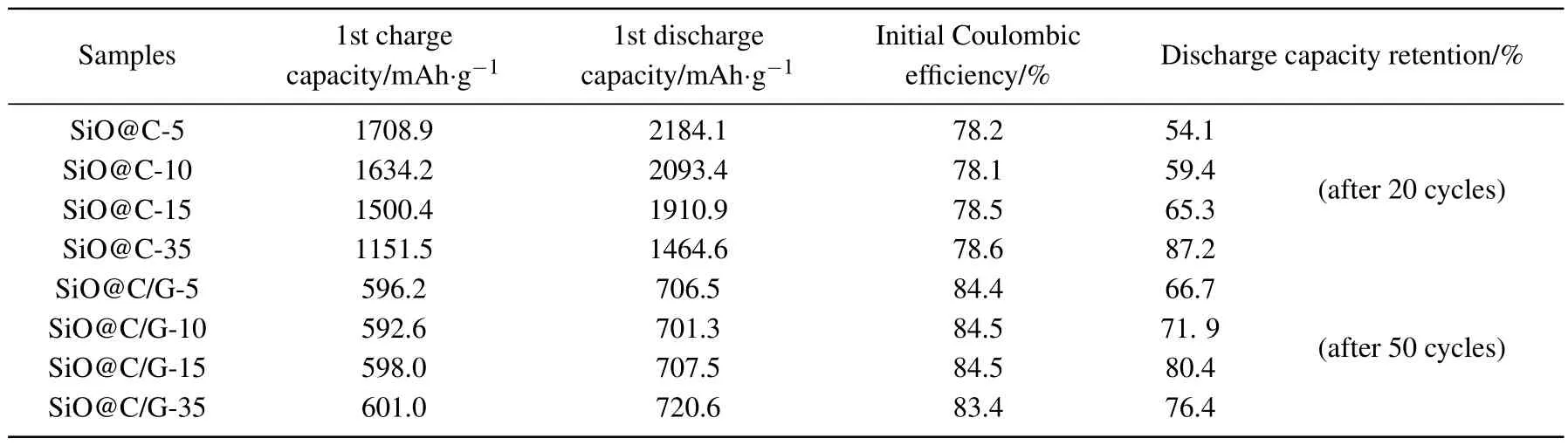
Table 2.The electrochemical performance of SiO@C samples and SiO@C/G composites in half cells.
SiO@C/G composites are prepared to further improve the long-term cycle stability of SiO@C.To match the capacity of positive electrode materials,the initial charge capacity of SiO@C/G composites is designed to 600 mAh·g-1(the highest charge capacity of commercial silicon-based anodes)by introducing different mass ratios of graphite powders.The galvanostatic charge-discharge tests of SiO@C/G composites are performed at a current density of 0.1 A·g-1in the voltage range of 0.005 V-2.0 V in coin-type half-cell firstly.The electrochemistry performances are displayed and summarized in Fig.4 and Table 2.The initial charge capacities of SiO@C/G-5,SiO@C/G-10,SiO@C/G-15,and SiO@C/G-35 are 596.2 mAh·g-1,592.6 mAh·g-1,598.0 mAh·g-1,and 601.0 mAh·g-1,respectively,which are in good accordance with the designed value of 600 mAh·g-1.All the SiO@C/G composites show higher initial coulombic efficiency and better cycling performance than the SiO@C samples, illustrating that the introduction of graphite is bene ficial to further improve the long-term cycling life of SiO@C.Among all SiO@C/G composites,the SiO@C/G-15 sample exhibits the best capacity retention of 80.4%after 50 cycles,while for SiO@C/G-5,SiO@C/G-10,and SiO@C/G-35,the capacity retention is 66.7%,71.9%,and 76.4%,respectively.The capacity retention of SiO@C/G-35 is slightly poorer than that of SiO@C/G-15 because a smaller amount of graphite is added(lower capacity of SiO@C).

Fig.5.Charge/discharge pro files of SiO@C/G||NCM full cell(a)at 2nd cycle and(b)at 100th cycle,the corresponding differential capacity(dQ/dV)plots(c)at 2nd cycle and(d)at 100th cycle,the cyclic performance of full cells(e)at 25 °C and(f)45 °C,and(g)the rate performance of the full cells.
To evaluate the feasibility of the SiO@C/G composite anodes for practical application,2.5-Ah pouch-type full cells are assembled with the as-synthesized SiO@C/G composites as anodes and the commercially available LiNi0.5Co0.2Mn0.3O2as the cathodes.Figures 5(a)and 5(b)show the chargedischarge curves of the SiO@C/G‖NCM full cells at the 2nd and 100th cycles,respectively.The full cell with SiO@C/G-15 exhibits the highest discharge capacity of 2212.9 mAh·g-1after 100 cycles. The corresponding differential capacity(dQ/dV)plots of SiO@C/G||NCM full cells exhibit similar peak features at 2nd cycle(Fig.5(c))and at 100th cycle(Fig.5(d)).The intense peak between 3.95 V and 4.1 V is ascribed to the delithiation of graphite.This peak in SiO@C/G-15 remains in the highest voltage range after 100 cycles,indicating that the polarization of SiO@C/G-15 electrode is minimal among the SiO@C/G composite electrodes.It is expected that the polarization caused by electronic conductivity is negligible due to the introduction of graphite and the measurement of dQ/dV at such a low rate of 0.02 C.Therefore,it can be further inferred that the SiO@C/G-15 maintains better ionic conductivity than other SiO@C/G composites during cycling.As shown in Figs.5(e)and 5(f),the full cells with SiO@C/G-15 exhibit the best capacity retention of 90.7%and 90.1%at 25°C and 45°C,respectively(Table 3).Thus,stable cycling is achieved with SiO@C/G-15 composite electrodes in full cells even at a high temperature of 45°C.The rate capabilities of full cells at different current densities are exhibited in Fig.5(g).The charge capacity gradually decreases with the increases of rate from 0.5 C to 5 C.A notable drop of the charge capacity occurs at a high rate of 10 C.
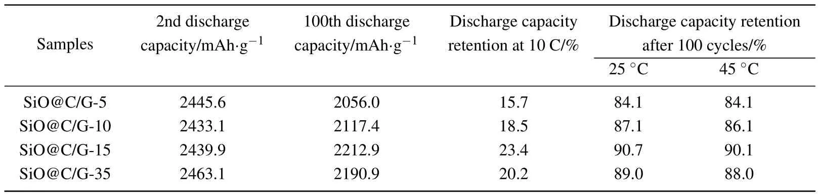
Table 3.The electrochemical performance of SiO@C/G||NCM full cells.

Fig.6.SEMimagesof(a)and(e)SiO@C/G-5,(b)and(f)SiO@C/G-10,(c)and(g)SiO@C/G-15,(d)and(h)SiO@C/G-35composite electrodes collected in full cells after 2 cycles,and(i)and(m)SiO@C/G-5,(j)and(n)SiO@C/G-10,(k)and(o)SiO@C/G-15,(l)and(p)SiO@C/G-35 composite electrodes after 100 cycles.
The morphology of the SiO@C/G electrodes after 2nd cycle and 100th cycle in full cells is investigated by SEM(Fig.6).It can be seen that there is no particle pulverization and fracture in the SiO@C/G composite electrodes,even after 100 cycles,indicating that the carbon coating layer and graphite skeleton play a signi ficant role in buffering the volume swelling of SiO particles and enhancing the mechanical stability of SiO electrodes.Figures 6(a)-6(h)show the sur-face morphology of SiO@C/G composite electrodes after two cycles.It is obvious that the particle surface of the SiO@C/G composites,especiallySiO@C/G-5,iscoveredbyarough film(Fig.6(e)),which can be ascribed to the solid-electrolyte interphase(SEI) film.After 100 cycles,the thickness of SEI increases on the surface of SiO@C/G particles(Figs.6(i)-6(p)).It can be clearly observed in Fig.6(m)that the SiO@C/G-5 particle is almost completely covered by a thick SEI film.In contrast,no signi ficant changes of surface morphology can be observed on SiO@C/G-15 after cycling compared with SiO@C/G-5,SiO@C/G-10,and SiO@C/G-35.These results suggest that a carbon coating layer with moderate thickness will be propitious to effectively form a stable SEI film and maintain a high ionic conductivity for the SiO@C/G composite,thus enhancing its long-term cycling stability.
To further understand the difference in the electrochemical performance of SiO@C/G composites,electrochemical impedance spectroscopy measurements are performed with full cells.As shown in Figs.7(a)and 7(b),the Nyquist plots consist of a small intercept at high frequency region(corresponding to the ohmic resistance,Ro),several semicircles at the medium frequency region(corresponding to the interface resistance and charge transfer resistance,RSEIand Rct),and a sloping straight line at the low frequency region(corresponding to the Warburg impedance,W).Figures 7(c)and 7(d)show the EIS fitting results of full cells after 2nd and 100th cycles.SiO@C/G-15 exhibits the minimum RSEIand Rctthan those of SiO@C/G-5,SiO@C/G-10,and SiO@C/G-35 after the 2nd and 100th cycles,implying that better ionic conductivity can be maintained in the SiO@C/G-15 electrode after cycling,which is consistent with the variation of delithiation peak voltage of graphite derived from dQ/dV plots in Figs.5(c)and 5(d).In contrast,the SiO@C/G-5 electrode displays significantly larger RSEIand Rctafter 100 cycles due to the increase in SEI thickness,which can be inferred from the SEM results as shown in Fig.6(m).These results suggest that a moderate carbon coating layer can effectively stabilize the solid/liquid interfaces between the SiO@C/G composite electrode and electrolyte and maintain better ionic conductivity during cycling,thus greatly improving the long-term cycling stability.

Fig.7.The Nyquist plots and corresponding fitting parameters of SiO@C/G‖NCM full cells after(a)and(c)2nd,and(b)and(d)100th cycles.The inserts are the corresponding equivalent circuits.
4.Conclusions
In summary,the micro-sized SiO@C/G composites with different thicknesses of carbon coating layers have been controllably synthesized via a pitch pyrolysis reaction method followed by a ball-milling process.Uniform amorphous carbon coating on SiO particle with thicknesses of 11.9 nm,21.6 nm,36.8 nm,and 81.0 nm is achieved,for SiO@C-5,SiO@C-10,SiO@C-15,and SiO@C-35,respectively.The capacity retention and coulombic efficiency of SiO@C samples are gradually improved with the increase of carbon content.For practical application,SiO@C/G composites have been fabricated with the target overall capacity of 600 mAh·g-1.Among all the SiO@C/G composites,the SiO@C/G-15 composite electrode exhibits a high initial coulombic efficiency of 84.5%and an outstanding capacity retention of 90.7%at room temperature and 90.1%at high temperature of 45°C after 100 cycles in full cells with NCM as cathode.Therefore,a carbon coating layer with a moderate thickness will be propitious for SiO@C/G composites to effectively form a stable SEI film and maintain a high ionic conductivity during cycling,thus enhancing the long-term cycling stability.The new insights into SiO@C/G composites presented in this work will promote the commercialized application of SiO anode materials.

- Chinese Physics B的其它文章
- Topological superconductivity in a Bi2Te3/NbSe2heterostructure:A review∗
- The universal characteristic water content of aqueous solutions∗
- Neutral excitation and bulk gap of fractional quantum Hall liquids in disk geometry∗
- Direct deposition of graphene nanowalls on ceramic powders for the fabrication of a ceramic matrix composite∗
- Hard carbons derived from pine nut shells as anode materials for Na-ion batteries∗
- Crystal structures and sign reversal Hall resistivities in iron-based superconductors Lix(C3H10N2)0.32FeSe(0.15<x<0.4)∗