
The design of 2/8-type high-pressure cell applied to in situ neutron diffraction∗
2019-08-06 02:06ChunJiangXiang向春江QiWeiHu胡启威QiangWang王强LeiXie谢雷XiPingChen陈喜平
Chinese Physics B 2019年7期
Chun-Jiang Xiang(向春江), Qi-Wei Hu(胡启威), Qiang Wang(王强), Lei Xie(谢雷), Xi-Ping Chen(陈喜平),
Lei-Ming Fang(房雷鸣)2,†, and Duan-Wei He(贺端威)1,‡
1Institute of Atomic and Molecular Physics,Sichuan University,Chengdu 610065,China
2Key Laboratory of Neutron Physics and Institute of Nuclear Physics and Chemistry,China Academy of Engineering Physics,Mianyang 621999,China
Keywords: DIA-type apparatus,Kawai-type cell,in situ neutron diffraction
1. Introduction
With respect to high-pressure in situ x-ray diffraction,high-pressure in situ neutron diffraction (HPND) provides a unique tool at extreme condition for probing crystallographic structures of the many important materials containing light atoms including H(D), Be, B11, C, and N,[1-6]and giving structural information of liquid and glassy materials.[7-10]Besides, HPND provides indispensable information for understanding the chemical composition, stability, and optical properties.[11]However,in contrast with synchrotron sources,the intrinsically weak sources of neutron radiation available,reactor or spallation-based sources,demand large sample volume, leading to the compromise between data quality and maximum attainable pressures. According to experience and some semi-empirical considerations, the maximum achievable pressure Pmaxis approximately proportional to an inverse power of volumeV,i.e.Pmax∝V-n,with n ≈2-3.[12]This implies that the pressure limitation will sharply reduce if the sample volume increases.Therefore,the pressure had been limited in the kbar range in a long time since the HPND technology was employed.[13,14]High-pressure technology also has important implications for other disciplines. In the field of materials science, high pressure annealing significantly reduced the heat treatment temperature as for of thin-film material.[15]
During the past years, many high-pressure devices had been developed for neutron diffraction experiments, such as McWhan-type cylinder-piston cell[13]and opposed-anvils cell.[16,17]Nowadays the Paris-Edinburgh press equipped with the toroidal opposed cupped anvils has been widely employed in the HPND experiments.[12,18]A key feature of PE press is their small volume and “compactness”, i.e. their high capacity compared to their mass. A V3 (VX3) press has a capacity of 250 tones but only a mass of 50 kg,[19]which is crucial for neutron diffraction because of the very limited space in the neutron beam-line. This high-pressure device generates a wide range of pressures up to 10 GPa with single toroid tungsten carbide anvils and to 25 GPa with double toroid sintered diamond anvils.[18,20]However, this uniaxialloaded opposed-anvil cell usually generates large stress due to the absence of liquid transmitting medium.[18]Furthermore,because of the limitation of the cell volume improvement it is impossible for high-temperature experiments, which usually requires a mass of ceramic pressure-transmitting medium working as a thermal and electrical insulator. Alternatively,multi-anvil(MA)cell,such as cubic anvil and octahedral anvil cell, possesses a larger cell volume and a quasi-hydrostatic pressure environment and has been widely used in diamond synthesis[21]and x-ray diffraction experiments.[22]However,because of the limited space at neutron diffraction beam-line many large volume apparatuses are not suitable choices. The uniaxial-loading DIA-type apparatus has a smaller volume and the uniaxial-loading is transferred to the six-anvil by upper and lower guild blocks. In order to further enhance the cell pressure, an assembly of eight cubic anvils of tungsten carbide or sintered diamond with the octahedral pressure medium and gaskets, the Kawai cell, is squeezed by the six first-stage anvils.[21]This MA 2-6-8 type apparatus has the advantage of producing homogeneous pressures at larger sample volumes over competitive high-pressure devices such as the diamond anvil cell (DAC).[23-25]The attainable pressure and temperature can reach 83.7 GPa and 1500 K using sintered diamond as the second-stage anvil.[26]
Unfortunately, few high-pressure in situ neutron diffraction experiments were performed in the DIA-type Kawai cell.Although this guide block system is a simple and effective way to produce high pressure,there is no wide window for neutron diffraction and the second-stage anvils and guild block material attenuates the neutron signal significantly. In this work,in order to obtain larger space for angle-dispersion neutron diffraction, we tentatively modified the DIA-type Kawai cell(MA 2-6-8) into MA 2/8, suggesting that the six first-stage anvils are removed and the assembly of eight cubic anvils of tungsten carbide is driven by the guide blocks directly.Then we performed high-pressure in situ neutron diffraction using the apparatus based on the neutron scattering facility(Fenghuang)of China Mianyang Research Reactor(CMRR).The pressure can reach 5 GPa with truncation edge lengths 3 mm at the load of 300 kN.
2. Design apparatus
The MA2-8 cell is mainly divided into two parts, guide blocks and the gasket-sample assembly. Figure 1 shows the major parts of the 2/8-type high pressure apparatus: the guild block, the second-stage anvil, and the gasket-sample assembly. Figure 1(a) is an overall diagram of the 2/8-type cell.The uniaxial-loading is transferred into axles through the interaction of the guide blocks and the secondary pressurizing unit. There is no contact between the grooved bottom of the guide block and the secondary pressurizing unit during the experiment. The secondary pressurizing unit consists of eight second-stage tungsten carbide anvils, twelve gaskets, and an octahedron pressure medium with sample. The fixing of the device is accomplished using four Teflon nuts,which are transparent for neutron. The neutron beam is directed horizontally between the gap of second-stage anvils and then transmits through the gasket and sample(Fig.1(b)).
Figure 2(a) shows the optimization of the second-stage anvils. The second-stage anvil has a large truncation edge length (TEL) and a small TEL on the opposite sides of the body diagonal. The small TEL assembled with pressure medium and gaskets is used to generate high pressure. The large TEL is used to fit the sliding surface of guide block groove. We tested pressure generation using the second-stage anvil with edge length of the cubic anvil of 10 mm and 12 mm.But it failed no more than at 200 kN due to the rupture of the anvil bevels. To solve this problem, we made some improvements to the apparatus. The volume of the secondary anvil was increased,the edge length of the cubic anvil increased to 14 mm.The large TEL increases from 7 mm to 10 mm and the area is increased to twice as before.The stress at the truncation is inversely proportional to the area. Therefore, the stress of the large truncation is reduced under the same loading,leading to the expansion the range of loading. Meanwhile, the large TEL is machined to a 0.6 rounded corner. This makes it easier to slide between the guild block and the second-stage anvils.
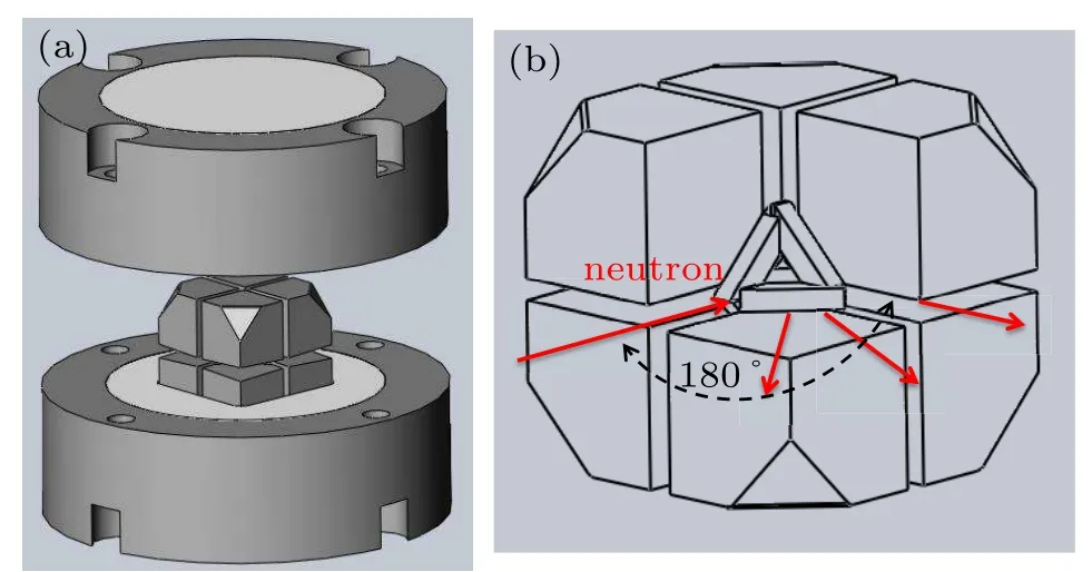
Fig. 1. (a) Overall diagram of the modified DIA-type Kawai cell.(b)The mode of high pressure neutron diffraction.
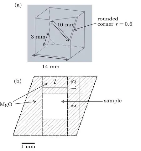
Fig. 2. (a) The optimization of the second-stage anvils. (b) The cross section of the octahedron transmitting pressure medium.
The octahedral edge length (OEL) of the pressure medium and the size of the TEL are the key points determining the volume of the sample and limitation of the cell pressure.[27]We design two kinds of small TEL,1.5 mm and 3 mm. Then we used an empirical method called “limiting compression volume ratio φ”to determine the size of OEL.[28]For small TELs of 1.5 mm and 3 mm,the corresponding OELs are 5.7 mm and 8.2 mm, respectively. The pressure media were octahedral MgO, which is a commonly used pressure medium owing to its large bulk modulus.[29,30]For the gaskets, we used raw pyrophyllite with a thickness of 2.45 mm(T)and a width of 2.94 mm(W)for a TEL of 3.0 mm,while T = 1.98 mm and W = 2.37 mm were used for a TEL of 1.5 mm. Figure 2(b) shows the cross-section of the 5.7/1.5 assembly.
3. Pressure calibration experiment
A series of pressure calibration experiments were carried out for the 2/8-type cell, including resistance calibration and in situ neutron diffraction.The ex situ pressure generation tests of the 2/8-type cell were carried out using the 300 kN servohydraulic press installed in the lab of High-pressure Science and Technology, Sichuan University. The machined octahedron transmitting pressure medium was cut in half, and the pressure maker was put inside it. A bit of the pressure maker was placed in the middle of the pressure media for pressure evaluation.Copper foil(0.1 mm thickness)was used as a wire,connected to the second-stage anvils and pressure maker. The assembled two-stage pressurization unit was put into the upper guild block and lower guild block to carry out a pressure calibration experiment. The phase transitions of ZnTe at 5 GPa was used as pressure fixed points to determine generated pressures,a piece of ZnTe single crystal was crushed into coarsegrained powder (grain size of 10-100 µm), which was used as the calibrant. Copper rods(0.8 mm in diameter)were used as electrodes and the calibrant was put in between the electrodes. The transition was also detected by two-wire electric resistance measurements.
The high-pressure in situ neutron diffraction experiments are performed on a high-pressure neutron diffraction spectrometer (Fenghuang) at the China Mianyang Research Reactor (CMRR). The monochrome beam with a wavelength of 1.59 ˚A was adopted for all neutron diffraction patterns.The detector consists of 703He counting tubes, scanning the diffraction angle from 8°to 172°. The size of incident neutron beam at sample position is about 2×3 cm2.[31]The loading force is generated by the 2000 kN Paris-Edinburgh press.[32]An iron cylinder (99.99%, Alfa Aesar, US) with a size of Φ2×2 mm was used as a sample. The sample pressure was continuously monitored in situ by using the equation of state (EOS) of crystalline Fe. We used the thirdorder Birch-Murnaghan isothermal EOS to calculate the sample pressure:[29]

where K0,K′0,and V0represent the bulk modulus,its derivative with respect to pressure,and the unit cell volume under ambient conditions,respectively. The pressures of Fe a-phase were obtained from the third-order Birch-Murnaghan equation using the measured K/K0, where K0=166.41 GPa, and K′0=5.32 obtained from the ultrasonic velocity measurement.[30]The corresponding cell volume V under different pressure conditions can be obtained via Rietveld refinements.
4. Results and discussion
Figure 3 shows the resistance of ZnTe associated with press loading. The experiment was performed using WC anvils with a TEL of 1.5 mm at room temperature. The edge length of the corresponding octahedral pressure medium is 5.7 mm. The phase transition occurs at 5 GPa with the resistance decreasing rapidly. The loading forces measured in the three experiments are 224 kN, 246 kN, and 220 kN, respectively. The loading value 230 kN is the average value of the three experiments,that is to say,the internal pressure reaches 5 GPa at 230 kN. Taking the average value as the reference value,the relative errors are calculated to be 2.6%,7.0%,and 4.3%, respectively. In the resistance calibration experiments,the average value of the relative error is 4.6%.

Fig.3. ZnTe pressure calibration results and fitted curves at room temperature. Pressure generation is based on 5.7/1.5 assembly using 14-mm tungsten carbide cubes as second-anvil.
Figure 4 shows neutron diffraction patterns collected at different loads. The curve(black)represents the neutron patterns collected at ambient condition. Only the(110)plane and(211)plane of Fe can be indexed because of the stronger peak intensity of tungsten carbide anvils and the MgO transmitting pressure medium. The curves(red)and(blue)in Fig.4 are the neutron diffraction patterns collected at 200 kN and 300 kN,respectively. With pressure increasing, (110) and (211) all shift to higher degree and the intensity weakens due to the decreases of the gasket thickness. This high-pressure in situ neutron diffraction is performed using WC anvils with a TEL of 3.0 mm at room temperature. The OEL of the corresponding octahedral pressure medium is 8.2 mm. The thickness of the gasket was 2.4 mm before the experiment,after a loading of 300 kN,the thickness of the gasket was 1.3 mm. The(211)peak is shifted to a higher degree and hides in the peak of tungsten carbide. The(110)peak still can be used for pressure calibration, and the unit-cell volume of Fe can be obtained at different pressures. The cell volume at room pressure (V0) is 23.57 ˚A3and the cell volumes are 23.10 ˚A3and 22.96 ˚A3at 200 kN and 300 kN, respectively. The cell pressure can be calculated using the EOS of Fe. Under loading of 200 kN and 300 kN,the achieved sample pressure is 3.5 GPa and 4.5 GPa,respectively.

Fig.4. The neutron diffraction patterns of iron collected under ambient conditions(black curve),200 kN(red curve),300 kN(blue curve),respectively. The black rhombus marks the peak of Fe. Other peaks are also shown,including guide block and anvils made of tungsten carbide and MgO pressure medium.
Figure 5 shows the pressure calibration curve obtained based on the resistance calibration of the phase transition and the neutron diffraction of Fe. A pressure of 5 GPa can be achieved at 230 kN using a 5.7/1.5 assembly. Compared with the 8.2/3 assembly, the area is reduced with the reduction of the TEL, so the same loading can produce higher pressure.The pressure calibration curve is nearly linear, which means that 5 GPa is not the limited pressure and can be further expanded by further optimization.

Fig.5. Pressure calibration curves obtained at room temperature. High pressure calibration curves using 8.2/3 are shown(black line). The red points represent the pressure calibration results using 5.7/1.5 assembly.
5. Conclusion
We have developed a new DIA type Kawai cell(2/8-type cell) for high-pressure in situ neutron diffraction. This device mainly consists of upper and lower guide blocks, and a two-stage pressurization unit that is composed of second-stage anvils,a pressure medium,and twelve gaskets. The maximum pressure that is achieved by this device is 5 GPa via the pressure calibration of resistance. The device has also been tested for high pressure in situ neutron diffraction. A pressure of 4.5 GPa is achieved using an 8.2/3 assembly at the loading 300 kN. Compared with the traditional PE press for in situ neutron diffraction, the new DIA type Kawai cell has a significant advantage in heating. This Kawai cell can provide steady internal heating rather than applying power directly to the anvil as in the PE press. In the future, the pressure range could be further expanded by replacing tungsten carbide anvil with polycrystalline diamond anvil. We will do high temperature and high pressure experiments, which will promote the progress in high pressure and high temperature in situ neutron diffraction.
猜你喜欢
东方少年(2022年25期)2022-10-18
新作文·小学低年级版(2022年5期)2022-08-30
Chinese Physics B(2022年4期)2022-04-12
无人机(2021年1期)2021-04-05
考试与评价·高二版(2020年1期)2020-09-10
考试与评价·高二版(2020年2期)2020-09-10
Chinese Physics B(2019年6期)2019-06-18
家庭影院技术(2017年8期)2017-10-13
中国篆刻·书画教育(2017年5期)2017-06-08
商情(2017年5期)2017-03-30

- Chinese Physics B的其它文章
- Coercivity mechanisms in nanostructured permanent magnets∗
- Progress in recycling of Nd-Fe-B sintered magnet wastes∗
- Grain boundary restructuring and La/Ce/Y application in Nd-Fe-B magnets∗
- Topology of triple-point metals∗
- Local evolutions of nodal points in two-dimensional systems with chiral symmetry∗
- Structural,elastic,and electronic properties of topological semimetal WC-type MX family by first-principles calculation∗