
Influence of multiple structural parameters on interior ballistics based on orthogonal test methods
2019-11-18 02:34ChaobinHuXiaobingZhang
Defence Technology 2019年5期
Chao-bin Hu, Xiao-bing Zhang
School of Energy and Power Engineering, Nanjing University of Science and Technology, China
Keywords:Multiple parameters Coupled model Combustion Sensitivity analysis Orthogonal test
ABSTRACT Influence of multiple structural parameters on the performance of a gun launch system driven by highpressure reactive gases is important for structural design and performance adjustment. A coupled lumped parameter model was utilized to predict the propellant combustion, and a dynamic finite element method was applied to approximate the mechanical interactions between the projectile and the barrel. The combustion and the mechanical interactions were coupled through a user subroutine interface in ABAQUS. The correctness and the capability of the finite element approximations in capturing small structural changes were validated by comparing predicted resistance with experiments.Based on the coupled model, the influence of structural parameters of a medium-caliber gun on the system performance was investigated. In order to reduce the research costs, orthogonal tests were designed to investigate the comprehensive effects of the parameters.According to statistical analysis,the important order of the structural parameters on the launching process was obtained.The results indicate that the influence of the width of the rotating band stands out among the studied parameters in the gun.The work provides a method to investigate the influence of multiple parameters on system performance and gives guidance for controlling the system performance.
1. Introduction
The function of a high-pressure propelling system [1e3] is to convert the chemical energy in energetic materials into the kinetic energy of launched objects.According to our previous works[4,5],the mechanical interactions between the projectile and the combustion chamber have significant influence on the system performance. Generally, a gun launch process is finished in several milliseconds and the maximum pressure in the combustion chamber reaches several hundred MPa. Furthermore, the mechanical interactions between the projectile and the barrel are accompanied by typical nonlinear factors such as geometrically large deformation of the mechanical parts, nonlinear constitutive properties and damage of materials. In addition, the mechanical interactions are affected by multiple structural parameters, which make the influence of a single factor difficult to identify.In order to make the influence of the structural parameters on the system performance clear for applications, thorough investigation of the parameters should be carried out.
To the authors' best knowledge, the interactions between the projectile and the barrel have not been thoroughly investigated.Many researchers have investigated the particular nonlinear mechanical interactions.Andrews[6]measured the strain on the outer surface of a barrel, which was caused by the high-pressure combustion products and the mechanical interactions between the projectile and the barrel. Wu et al. [7e9] experimentally studied the influence of material and loading rates on the engraving process of rotating bands. Balla et al. [10] and Chen et al. [11] analyzed dynamic response of rotating bands employing the finite element method (FEM). Toivola et al. [12,13] experimentally and numerically investigated the influence of geometries and material properties of rotating bands and long range artillery projectile shell bodies on gun tube stress. Yang et al. [14] compared the performance of numerical methods such as the FEM, the smoothed particle hydrodynamics method and the coupled Eulerian-Lagrange method in predicting the engraving process of a projectile. Qian et al.[15]presented uncertainty propagation analysis of the model coupling the projectile and gun barrel during an interior ballistic cycle. Xie et al. [16] investigated the deformation force during the launching of a small-diameter steel cartridge by using a semiclosed bomb test method. Zhang et al. [4,5] put forward a computational framework to couple the propellant combustion and the mechanical interactions and predicted the performance of a medium caliber gun in different life stages.
Though remarkable works have been done, few of them considered the coupling effects between the propellant combustion and the mechanical interactions. In the computational framework in our previous work[4],which considers the coupling effects,the mechanical interactions are predicted by utilizing a finite element method.Considering the transient effects and the nonlinear contact between the mechanical parts, the mesh size and the time step should be small enough to obtain a reliable approximation.Therefore, the method is time consuming and it is unrealistic to study the influence of those structural parameters by using this exhaustive method.In the field of applied statistics,orthogonal test design is a scientific method to shorten the development period of a new product based on orthogonal arrays and carries out mathematical analysis by statistical mathematics.In order to improve the investigation's efficiency, there are many applications of the orthogonal test method in engineering application fields. For example, Liu et al. [17] optimized the injection configuration in a zero boil-off hydrogen storage tank by utilizing orthogonal test design.In the present work, we utilized the method to investigate the influence of the structural parameters on the performances of a high-pressure propelling system.
2. Fluid-structure coupled model
The main components of a gun launch system are illustrated in Fig.1.The combustion of propellant is confined in a domain closed by the walls of the chamber and the base of the projectile. During the launch process, the base of the chamber is fixed while the projectile base moves forward. Therefore, the domain occupied by the combustion products expands along with the forward movement of the projectile. In order to guarantee the sealing effects of the combustion chamber,the outer diameter of the rotating band is usually larger than the inner diameter of the chamber. The rifling on the inner wall of the chamber is used to rotate the projectile,which provides gyro stability for the projectile while flying in the air.
In Fig.1, parameters h, W and a are the magnitude of interference between the rotating band and the grooves, the width of the rotating band and the forcing cone angle, respectively. The magnitude of interference h is defined in Eq.(1),in which dBis the outer diameter of the rotating band and dGis the diameter of the grooves.


Fig.1. The expanding combustion chamber.
In order to study the influence of structural parameters on the performance of the system, a numerical model that couples the propellant combustion and the mechanical interactions between the projectile and the chamber should be provided. The system is divided into two sub-systems. One considers the propellant combustion in the expanding chamber. The other one considers the mechanical interactions. The coupling effects are realized by exchanging parameters between the two sub-systems. In the present work, the propellant combustion is governed by a lumped parameter model,which is shown in Eq.(2).It should be noted that the propellant combustion is predicted based on the geometry burning law in the model.

where, j is the relative burnt mass of the propellant; Z is the relative burnt thickness of the propellant, Zkrepresents a burntthrough state of the propellant; v is the projectile velocity; l is the projectile travel; p is the spatial averaged pressure; m is the projectile mass; u1and n are two coefficients that determines the burning rate;c,l,m,cSand lSare shape-dependent constants of the propellant.In the energy equation,f is the propellant force;S is the effective cross section area of the barrel,u is the charge mass,g is the specific heat ratio,lj is the equivalent free chamber length and K represents energy flows that are proportional to the translational kinetic energy of the projectile.Different from the existing models,the work output of the combustion products through the base of the projectile is dealt separately,which is shown in the second term on the right side of the energy equation.The separation provides a convenience for coupling the mechanical interactions and the combustion.
The influences of the mechanical interactions on the propellant combustion are reflected through the kinetic equation of the projectile.In traditional models,a constant coefficient of energy losses is used to simplify the mechanical interactions. As discussed in those works [4,5,10], the resistance acting on the projectile is a function of the kinetic parameters of the projectile and the structural parameters of the gun bore and the rotating band.Therefore,the constant coefficient is not capable of reflecting the mechanical interactions. In the coupled model, the kinetic parameters of the projectile are obtained by using a dynamic finite element method(FEM), of which the governing equation is shown in Eq. (3).

where U, _U and €U are the displacement, velocity, and acceleration vectors, respectively; M, K and C are the mass, stiffness and damping matrixes, respectively; and Q is the loading vector.
3. Material damage and fracture
As illustrated in Fig.1,the outer diameter of the rotating band is larger than the inner diameter of the bore. Therefore, material damage and fracture on the rotating band are unavoidable during the engraving process of the projectile. In the present work, a Johnson-Cook constitutive model [18,19], which is illustrated in Fig.2,was utilized to depict the mechanical behavior of the rotating band.In the figure,E is the elastic modulus of the material,s0 is the elastic limit,sy0is the ultimate strength,is the equivalent plastic strain when the material damage starts, D is a damage parameter andis the equivalent plastic strain when the material is fractured. The last parameter is defined in Eq. (4).

where,d1is the initial failure strain,d2is the exponential factor,d3is the triaxiality factor, d4is the strain rate factor and d5is the temperature factor,spis the average of the three normal stresses;T is the temperature, T0is the ambient temperature and Tmeltis the melting point of the material.
For the damaged material on the rotating band,the stress-strain relationship is mainly comprised of an elastic stage (O-A) and a plastic stage (A-C). The damage of the material starts at point B in Fig. 2, while the fracture of the material occurs when the strain is large enough at point C.The dotted line H-G represents the stressstrain relationship while unloading after the damage starts.For the second stage, the stress-strain relationship is given in Eq. (5).

where,ε is the equivalent plastic strain; _ε is the plastic strain rate;_ε0is the reference strain rate;material parameters A,B,C,n and m can be obtained by experiments.In the present work,the material parameters were obtained in Refs. [18,19].

Fig. 2. Material constitutive for the rotating band.
For an element in a dynamic FEM approximation, the damage parameter D is defined in Eq. (6) in the present work, which is based on the equivalent plastic displacement of the element.

4. Verification and validation
The focus of the present work is investigating influences of structural parameters on system performances. Consequently, the correctness of the mechanical approximations should be validated first.In addition,the ability of the finite element approximation to capture small structural changes should also be validated.
Considering the extreme conditions in the combustion chamber,we studied engraving processes of projectiles in quasi-static conditions by using experimental and numerical methods. The structure of the projectile is illustrated in Fig.3.Two rotating bands are embedded on the projectile and d1represents the outer diameter of the rotating bands. To validate the ability of recognizing structural changes, two cases with different outer diameter d1were investigated. The rotating band diameters for the two cases are 31.0 mm and 31.3 mm, respectively. The caliber of the gun is 30 mm.
In the FEM approximations,a proper mesh size was determined by employing a simple trial and error method. The predicted resistances are compared with experiments in Fig.4.The mechanical behavior of the rotating bands is described by using the Johnson-Cook constitutive model. Related material constants for the rotating bands can be obtained in Refs. [18,19].
In both two cases,the calculated resistance agrees well with the measured resistance, especially the maximum value and the developing tendency.For Case II(d1¼31.3 mm),when the rotating bands were fully engraved into the barrel,the distributions of Von Mises stress and deformation on the rotating bands are presented in Fig.5.In the figure,the Von Mises stress is measured in MPa.The grooves on the rotating bands agree well with the configuration of the rifling on the barrel.
The outer diameter of the rotating bands in Case II is larger than that in Case I by 0.3 mm. The finite element approximation captured the structural differences and obtained a lager maximum resistance in Case II.Obviously,the comparison between the finite element approximations and the experiments indicates that the finite element approximation is capable of predicting the nonlinear mechanical behaviors and recognizing small structural differences.
5. Results and discussion

Fig. 3. Structural of the projectile for the validation.

Fig. 4. Resistance acting on the projectile.

Fig. 5. Distributions of Von Mises stress and deformation on the rotating bands.(d1¼31.3 mm).
Based on the validated model, influences of structural parameters determining the geometry of the main components of the propelling system on the performances were investigated. To guarantee the modeling accuracy, the mesh size and the related time step in the FEM approximations are very small.Therefore,the coupled model is time consuming.Orthogonal tests were designed to analyze the influences of the structural parameters.
5.1. Coupling strategy
To reflect the structural parameters influences on the system performance, the prediction of the propellant combustion and the approximation of the mechanical interactions should be coupled with each other. In the present work, the mechanical interactions were approximated basing on ABAQUS. The coupling was realized by using a user subroutine interface VUAMP in the software.
The user subroutine interface VUAMP was utilized to predict the propellant combustion and to obtain loading conditions for the mechanical approximations. Equations governing the combustion of the propellant were programmed in FORTRAN in VUAMP.Through the interface, the FEM calculation provides kinetic parameters of the moving projectile such as the travel and velocity of the projectile for the combustion calculated in VUAMP.In turn,the combustion simulated in VUAMP provides loading conditions for the FEM approximation.
5.2. Design of the orthogonal test
In the finite element method, the mesh size used to discretize the rotating band and the barrel should be small enough to obtain convergent approximations and to depict the mechanical interactions accurately. The engraving process of rotating bands in the second case in Section 4 is illustrated in Fig.6.The mesh on the rotating band is given in Fig.7.To obtain a convergent solution,the minimum size of the mesh on the rotating band is about 0.25 mm,which locates at the outer surface of the rotating band. A small mesh size leads to a minor time increment and a large number of elements, which further leads to a terrible computational cost. In order to investigate the influence of the structural parameters on interior ballistics, a large number of cases should be calculated,which means an enormous amount of work.In order to investigate influence,the orthogonal test is an excellent method to reduce the research costs.The essence of the method is principles in statistics.

Fig. 6. Engraving process of the rotating bands.

Fig. 7. Mesh on one of the rotating bands.
The following four structural parameters were investigated:the magnitude of interference between the rotating band and the grooves h,the width of the rotating band W,the forcing cone angle a and the twist angle of the rifling.In the remainder of the article,those parameters are indicated as A, B, C and D, respectively. Five levels are considered in the work for each factor, which are illustrated in Table 1.
In the work, four parameters have been investigated and each parameter has five levels. Therefore, the L25(56) orthogonal array shown in Table 2 was adopted to perform the investigation. In the table,numbers in the first column are case numbers.Numbers from the second column to the seventh column represent the corresponding levels. It should be noted that the interactions between the factors were ignored in the present work.
5.3. Results
The comparison of the resistance in Fig. 4 only validates the effectiveness of the mechanical approximations. The capability of the coupled computational framework for predicting the system performance should be further validated.Considering the extreme conditions in the barrel,parameters that can be reliably measured are limited. In the present work, we measured the maximum pressure at the breech of the barrel and the muzzle velocity of the projectile for structural parameter combination of Case 14 in Table 2.The calculated results are compared with the experiments in Table 3. After the rotating band was fully engraved into the barrel, the Mises stress and deformation of the rotating band are illustrated in Fig. 8. The grooves on the rotating band agree well with the rifling of the barrel. In Table 3, both the two critical parameters agree well with the experiments,which indicate that the mathematical model and the computational framework are capable of reflecting the interactions between the mechanical response and the combustion.

Table 1 Orthogonal factor and level list.

Table 2 L25(56) orthogonal designed scheme and results.

Table 3 Results at special moments.

Fig. 8. State of the rotating band when it is engraved into the barrel.
Similar to the model validation,the maximum pressure and the muzzle velocity of the projectile were selected as indicators to analyze the influences of the structural parameters on the system performances.The corresponding results are shown in the last two columns of Table 2.In the present work,range analysis was adopted to investigate the results of the orthogonal tests. The sum of the indicators Kijand the average valuesfor level i under factor j(i¼1,2,3,4,5;j¼1,2,3,4)were calculated and given in Table 4.When factor j is determined, the difference among these average valuesreflects the effects of the levels for factor j on indicators. Based on the following equation, the ranges Rj(j¼1,2,3,4) were calculated.

Table 4 The range analysis of the indicators.

Comparing the calculated ranges, we found that the important order of these structural parameters on the maximum pressure is as follows:the width of the rotating band(B),the forcing cone angle(C), the magnitude of interference between the rotating band and the grooves(A)and the twist angle of the rifling(D).The important order of the parameters on the muzzle velocity is the same with that on the maximum pressure for the studied gun.
5.4. Discussion
The rationality of the order of importance and the inherent mechanism of the effects on the system performances are further discussed. The units and ranges of the structural parameters are different from one another.Therefore,the direct comparison of Rjis unpersuasive.Consequently,we obtained the normalized ranges R0jby using Eq. (8).

where Dh is the normalized parameter intervals, which is a ratio between the parameter interval and the standard level. The standard level is the value of a parameter used in a new gun. The normalized ranges are given in the penultimate row of Table 4.Obviously, in the selected parameter ranges, the order of importance of the structural parameters on the two indicators is not changed for the studied gun.
In addition, the standard deviations of the indicators were calculated to further validate the results.The standard deviation sjis defined as follows.

where AVEjrepresents the average value of an indicator under factor j. The results are presented in the last row of Table 4. The standard deviations of the maximum pressure and the muzzle velocity are illustrated in Fig. 9 and Fig. 10, respectively. A larger deviation suggests that the change of the factor has a greater significant influence on the indicator. Obviously, the accuracy of the order of importance of the structural parameters obtained in Section 5.3 is further validated.
Addition to the order of importance, influence of single parameters, especially the leading factors, such as the width of the rotating band (B) and the forcing cone angle (C), on the performance of the system can also be discovered.The effects of the two factors on the maximum pressure and the muzzle velocity are presented in Fig.11 and Fig.12, respectively.
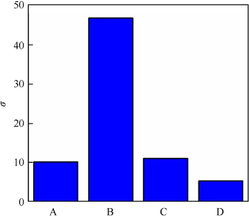
Fig. 9. The standard deviation of the maximum pressure.

Fig.10. The standard deviations of the muzzle velocity.

Fig.11. The maximum pressure.
For the effects of the two leading factors on the system performance, which are shown in Fig. 11 and Fig. 12, the maximum pressure is easier controlled than the muzzle velocity through adjusting the structural parameters. The projectile motion is determined by the combination of the base-pressure and the resistance acting on the projectile. In return, the projectile motion determines the volume of the combustion chamber. Obviously, a larger resistance makes a slower enlargement of the combustion chamber. Consequently, a larger maximum pressure can be reached.
For the muzzle velocity, the influence of the structural parameters is effective throughout the working process.According to the ranges and the standard deviations,the width of the rotating band stands out among the studied factors. Therefore, we further explicate the effects of the factor on the indictors shown in Fig.11(a)and Fig.12(a). The width of the rotating band determines the effective contact area between the projectile and the barrel.A wider rotating band leads to a larger maximum pressure. On the other hand, the resistance acting on the projectile is greater.Considering the curve slopes in the two figures, the slope in Fig.10(a) increases with the increasing width of the rotating band.While in Fig.12(a),the slope tends to decrease. The phenomenon results from the competition between the base pressure and the resistance.
6. Conclusions
Based on the model that couples the propellant combustion and the mechanical interaction, orthogonal tests were designed to investigate the influence of structural parameters on the system performance of a high-pressure propelling system.According to the model validation and the results obtained in the orthogonal tests,the following conclusions can be drawn.
(1) The dynamic finite element calculation can sensitively capture small structural changes and correctly approximate the mechanical interactions accompanied by nonlinear factors such as material interactions and damage.
(2) The coupled model is capable of reflecting the interaction between the propellant combustion and the mechanical interactions between the projectile and the expanding combustion chamber.
(3) For the studied gun and the selected parameter ranges, the order of importance of these structural parameters on the maximum pressure and the muzzle velocity are the same.The order of importance is as follows: the width of the rotating band, the forcing cone angle, the magnitude of interference between the rotating band and the grooves,and the twist angle of the rifling.

Fig.12. The muzzle velocity.
(4) For the studied gun, the width of the rotating band can be used to adjust the performance of the system over a wide range, while the other three parameters can be used to realize small adjustments.
Acknowledgments
We are grateful for the financial support from the Postgraduate Research&Practice Innovation Program of Jiangsu Province(Grant No.KYLX_0399).

- Defence Technology的其它文章
- Comparative analysis of the effects of gunpowder and plasma ignition in closed vessel tests
- Numerical simulation on the pressure wave in a 30 mm electrothermal-chemical gun with the discharge rod plasma generator
- Design optimization for a launching system with novel structure
- Design and manufacture of a 100 kA coaxial pulsed power cable for plasma generator and PPS in ETC guns
- A prediction method for the performance of a low-recoil gun with front nozzle
- Effect of the firing position on aiming error and probability of hit