
Modeling and simulation of bullet-barrel interaction process for the damaged gun barrel
2020-01-07 09:11ChoShenKedongZhouYeLuJunsongLi
Defence Technology 2019年6期
Cho Shen ,Ke-dong Zhou ,*,Ye Lu ,Jun-song Li b
a School of Mechanical Engineering,Nanjing University of Science and Technology,Nanjing 210094,Jiangsu,China
b No.208 Institute of China Ordnance Industry,Beijing 102202,China
ABSTRACT In this paper,the influences of bore damage on the bullet-barrel interaction process and the mechanism of how bore damage results in the end of a machine gun barrel's service life were studied,which had seldom been paid attention to in the past several decades.A novel finite element mesh generation method for the damaged barrel and a new transient coupled thermo-mechanical finite element(FE)model,which were based on the damage data obtained through barrel life tests,were developed to simulate the interior ballistics process of a coupled bullet-barrel system.Additionally,user subroutine VUAMP was developed in the FE model in order to take the bullet base pressure brought by propellant gas into account.Good consistency between the simulation results and the experimental results verified the preciseness of the proposed mesh generation method and the FE model.The simulation results show that the increase of bullet's initial disturbance at the muzzle and the variation of its surface morphology caused by bore damage are primarily responsible for the life end of this 12.7 mm machine gun barrel.
Keywords:Barrel life tests Real bore damage Interior ballistics performance Initial disturbance Finite element method
1. Introduction
The interior ballistics process consists of the engraving and the following in-bore motion of the bullet during a firing cycle[1].During the process,the bullet accelerates and rotates to keep the flight stability after leaving the gun barrel.The assembly relation of the 12.7 mm bullet and the barrel is shown in Fig.1.The initial velocity,the initial velocity direction and the initial rotation velocity of the bullet constitute the initial conditions of the exterior ballistic process.With constant firing rounds,damage occurs in the bore and get worse and worse. Besides, mainly due to the complicated mechanical and thermo-chemical environment when firing,damages in bore present different morphology longitudinally.Any little aforementioned damage in bore will impact on the interior ballistic process apparently and finally affects the bullet's muzzle states which are initial conditions for the exterior ballistics phase.Damaged bore will also change bullet's surface topography when it reaches the muzzle and its aerodynamic parameters.Bullet's initial disturbance together with its muzzle surface topography constitutes the final states of the interior ballistics process called bullet's muzzle states,which have a great influence on the exterior ballistic performance and firing accuracy.Therefore,for better understanding of how small arm's firing accuracy decreases and how barrel life ends,it is significant to investigate bullet's interior ballistic performance and muzzle states for a real damaged bore.
Many scholars have studied the damage process of gun barrel both experimentally and numerically in the past three decades.Coat et al.[2]carried out several experiments on erosion damage in chromium-plated gun bore surface,based on which new insights regarding the erosion process and the origin of chromium loss were obtained.Lawton[3]studied the thermo-chemical wear mechanism about the gun barrel and derived a relationship between wear and bore temperature with both theoretical and experimental methods.Chung[4]developed a precise wear measurement system to measure the wear rate of a gun barrel under high friction and pressure.Sopok et al.[5]described a thermal-chemical-mechanical gun bore erosion theories and mechanisms for an advanced artillery system and its associated laboratory-firing simulator system.These erosion theories and mechanisms were subsequently used to develop erosion models for each of the coating types used in this advanced artillery system and its simulator. Rosset et al. [6]determined the degree of wear and erosion owing to excessive firing duration by multiple firing tests where a small caliber experimental gun barrel made of a cobalt-base alloy was used,and proposed that small amount of barrel material loss made the cobalt-base alloy an excellent candidate for use as a gun liner.Wu et al.[7]presented a novel strain-based approach for gun barrel's life prediction and did theoretical analysis on testing results using strain of the gun barrel's outside surface as a health index.
In addition, lots of researchers have studied the coupled projectile-barrel behavior during the interior ballistics process.Wu et al.[8]found that strain rate and temperature had great effects on the deformation behavior of rotating band during engraving process form the quasi-static and dynamic experimental results.Ding et al.[9]proposed a new parametric geometric modeling method for gun barrel and a new finite element meshing strategy for the worn barrel,which involved the joint use of Python code and ABAQUS software.Montgomery[10]found that there are two apparently different wear mechanism of the rotating band.Specifically,when a molten film is formed on the band surface,the contact between rotating band and barrel gets lubricated and friction is only determined by hydrodynamic considerations.Yin et al.[11]studied the thermal softening mechanism and structure evolution of surface metal under the sudden increase of temperature with kinetics of recrystallization.A correlation between the diametral wear of a small arms barrel and the bullet structure of a sniper cartridge,presented by Zelenko et al.[12],showed that it is possible to separate two typical segments of barrel wear for a monolithic bullet,and three segments for a full-jacketed bullet.et al.[13]investigated the influence of the barrel fixing on barrel vibration when a 5.56 mm bullet moves down the barrel by numerical simulation.South et al.[14]proposed a method of examining the engraving force and the resulting projectile deformation through rate-controlled push tests and evaluated the projectile response to engraving over a range of loads and loading rates.Andrews[15]carried out a series of trials to determine the effect of the projectile driving band on the stress of a 155 mm gun barrel during firing.The strain gage data from firing trials were used to characterize the external strain of different projectiles and charges to identify potential problems,and to provide information for fatigue analysis.
The above researchers tried to explain the damage mechanism of barrel and the effects of interaction between bullet and barrel.Nevertheless,due to the complicated gun barrel configuration and damage form,the accurate 3D finite element model of the barrels with real bore damages,which includes crack,wear,ablation crater and spalling of surface metal and so on,has hardly been established.Furthermore,instead of focusing thoroughly on the bullet's interior ballistic performance,the key point in studying the bulletbarrel interaction process lies in finding the connection parameters between interior and exterior ballistics since firing accuracy is a significant criterion for judging whether the barrel life ends or not.These parameters are called the bullet's muzzle states and will be amply discussed in section 3.
In order to study the interior ballistics performance,to obtain the bullet's muzzle states under chromium-plated gun barrel with real damages,and to better understand how damage of bore reduces firing accuracy and shorten a barrel's service life,a mesh generation method for barrels with real damages was developed based on the distribution and evolution rule of damages along barrel axis obtained through a series of barrel life tests.On this basis,thermo-mechanical finite element analysis(FEA)models of chromium-plated barrels at four life periods were established by means of Python code pre-processing and ABAQUS/CAE software(ABAQUS/Explicit).After that,equations of the interior ballistic process,which took engraving resistance and volume increase behind the bullet caused by bore damage into consideration,were combined into the FEA model through user subroutine.Then,by analyzing the simulation results,bullet's interior ballistic parameters as well as its muzzle states for the barrels at four life periods and how bore damage influences them were acquired.Finally,associated conclusions about the interaction between bullet and damaged gun barrel were obtained.
2. Materials and methods
2.1. Main forms of bore damage and its distribution and evolution law with the increase of firing cycle
The aim of this section is to find the main forms of bore damage and its distribution rules of a 12.7 mm machine gun barrel according to a series of barrel life tests.All the bore damage data in section 2 were acquired through barrel life tests of several 12.7 mm machine guns under same shooting criteria and all the tested barrels had same material,same structure and same manufacturing process.Therefore,main forms of damage,as well as its distribution and evolution rules concluded in this section are generally conformable for this 12.7 mm large-caliber machine gun barrel.This kind of large-caliber machine gun shoots for 6000 rounds before running out of its life.
Bore damage form can be concluded to two main types according to massive barrel life tests.
(1)The first type of the damage is the expansion of gun barrel's diameters both in land and in groove due to the wear of surface metal material on bore as shown in Fig.2;

Fig.2.Wear of bore near the gas port.

Fig.3.Local damages on bore:(a)cracks,(b)ablation and metal spalling.
(2)The second type is the local cracks,ablation craters and spalling of coating metal on bore due to the uneven mechanical,chemical ablation and thermal stress effects when firing as shown in Fig.3.
Bore damage forms concluded from life tests correspond with the descriptions in Ref.[16].The wear value of the first type of damage can be measured by plug gauges,while the damage form and distribution law of the second type of damage are acquired through bore peeping or anatomizing the barrel as shown in Fig.4.
2.1.1. Wear value and its variation rule of barrels at different life periods
For the first type of bore damage,it could be concluded that the wear value and variation rule of the tested barrels are almost the same according to the life tests.For example,the land diameters of three of the tested barrels at mid-term of the life period are presented in Fig.5.The mean value of the land diameters of the three tested barrels at 4 life periods from the origin of rifling to muzzle are demonstrated in Fig.6.The firing cycle number of the 4 periods is 0,1400,3000 and 6000 respectively and barrel life ends at 6000.These 4 periods are numbered 1-4 with the increase of the shooting rounds to facilitate description.Wear value increases when the land diameter of bore becomes larger in Fig.6.
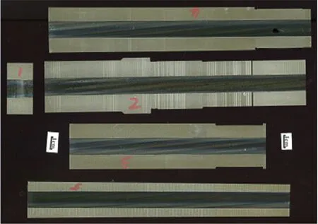
Fig.4.Longitudinal cross-section of the test barrel.

Fig.5.Land diameters of three of the test barrels at mid-term lifetime.
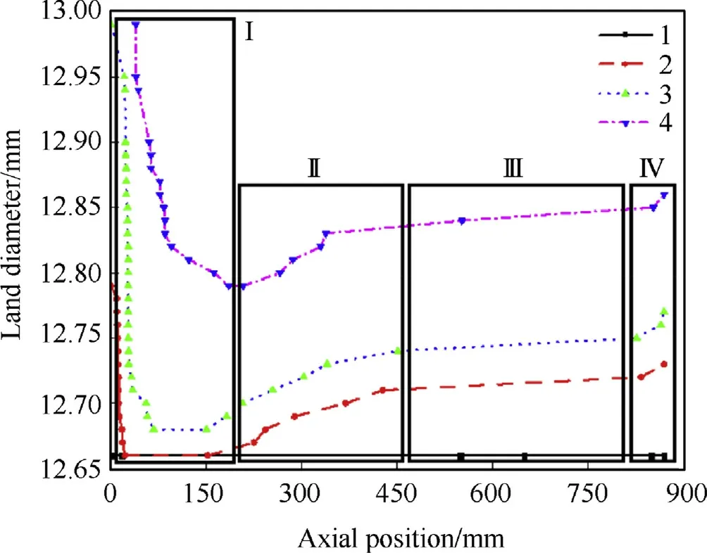
Fig.6.Bore diameter of the 4 barrels along the axis.
As shown in Fig.6,the diameter of the barrel land was 12.66 mm initially and expanded significantly with the increase of friing cycle.Additionally,it is similar for the 4 periods of the barrels'land diameters to change and the whole barrel can be divided into four areas longitudinally.AreaIis almost 12-caliber far from the origin of rifling,in which the maximum wear value appears at zero position and swiftly decrease to their own definite stable values.AreaIIstarts from the end of areaIand ends at the approximate axial middle position of the barrel,where the wear value increases nonlinearly.Area Ⅳis about 2-caliber far from the muzzle,and the rest belongs to area III.Wear value increases linearly and slowly in area III,while the wear value becomes larger suddenly and rapidly in area Ⅳ,for which the muzzle looks like a‘trumpet’.In this study,areaIand areaIIare called the main wear area,area III is called the uniform wear area,and area Ⅳis called the muzzle wear area.
2.1.2. Main form and distribution rule of local damage of barrels at different life periods
The cross-section of the 12.7 mm machine gun barrel seen from the breech is shown in Fig.7,which is a hollow tube with lands and grooves.The rifling consists of eight lands and eight grooves,and the radii of which areRLandRGrespectively.The left side of the land seen from the breech is the forcing side as the rifling is dextral,which is the same to all the endoscopy images listed in this section.
When it comes to the second type of damage,the main form and distribution rule of the damages for each of the tested barrel are similar on basis of the life tests,which is the same with the first type of bore damage.For instance,the endoscopy images of three of the tested barrels at mid-term of the lifetime in areaIare displayed in Fig.8.Under such circumstances,one typical barrel was chosen to demonstrate the main form and distribution rule of the second type of bore damage.
Endoscopy images of the barrel at the beginning part of the rifling among the 4 life periods are shown in Fig.9,where area-Idamaged most seriously.The images of the terminal part of this area are shown in Fig.10.

Fig.7.Cross-section diagram of the barrel seen from the breech.
According to Fig.9 and Ref.[16],the main damage forms of barrels at the origin part of the rifling are the spalling of coating metal caused by the extension of initial reticular cracks,and the ablation craters caused by the scour of gas-solid mixture generated by propellant combustion.According to Fig.9(b),reticular cracks at the beginning of rifling had already transformed into ablation craters and coating metal spalling at barrel's early life period.Besides,distribution rules of damage at the origin part of the rifling could be concluded from Fig.9.During a barrel's lifetime,damages on the land of bore appeared at the origin segment of rifling firstly,and extended along the rifling to both the muzzle and the breech directions.Damages on the left side of the land which is called the driving side and forces the bullet to spin were heavier than the other side due to more critical working state when firing.When it came to the groove,damages on it also appeared at the origin segment of rifling firstly.The difference was that the damages extended along the rifling just to the muzzle direction and met the land damages in the circumferential direction.The reason for this phenomenon is that damages on the groove were mainly caused by the scour of leaking gas-solid mixture with high temperature and high velocity through the clearance between bullet and barrel,and the scour action was much lighter during the engraving process since there was not enough space for gas to leak.Additionally,as presented in Fig.10,damages on the lands and the grooves had extended to the terminal of areaIfor barrel at life period 4 which had run out of its life.
Bore endoscopy images of the barrel at 4 life periods in areaIIare displayed in Fig.11.In this area,a barrel just wore at its early life period,and the coating metal on the driving side of the land began to flake when the firing cycle exceeded 3000.Besides,ablation craters appeared on the groove at barrel's later life period.The reason is that at later life period of the barrel,damages in areaIwere so heavy that bullets were not constrained well in this area,which may lead to larger moving disturbances of bullets and greater reaction force on bore in areaII.Besides,areaIIwas also the highest temperature area of the barrel axially during cyclic firing according to Ref.[17],causing greater thermal stress in this area and leading to the coating metal easier to flake.What is more is that bullets had greater acceleration and angular acceleration in this area throughout the whole interior ballistics process,which enlarged the driving force on land's driving side.These three reasons explain the phenomenon of coating metal spalling on land's driving side in areaII.As to the ablation craters on the groove,the reason is that the wear of bore expanded the clearance between bullet and barrel,which aggravated the leak of propellant gas and the scour action on the groove.
As shown in Fig.12,bore damages in area III and area Ⅳare in the form of uniform wear.Bore pressure,acceleration and angular acceleration of bullets were relatively lower in these two areas,which contributed to bullets’reposeful motion,lighter force and lighter damage on bore.
2.2. Mesh generation method for damaged barrel
Both two types of bore damage form described in section 2.1 will significantly influence the interior ballistic process and bullet's muzzle state.It is foreseeable that the wear of the surface metal on bore,known as the first type of damage,will enlarge the clearance between bullet and barrel,which will increase bullet's muzzle disturbance,reduce its rotational velocity and decrease its flight stability finally. Besides, the local cracks, ablation craters and spalling of coating metal on bore,known as the second type,will alter bullet's surface morphology and then vary its aerodynamic parameters during exterior ballistic process.Hence,both two types of bore damage form must be taken into consideration when generating the mesh of real damaged barrel.
2.2.1. Assumptions and simplifications for damage
It is necessary to be aware that real damaged bore morphology is too complicated to reappear through FEA methods completely,because of which the mesh generation process of damaged barrels was conducted under the assumptions below.
(1)Wear of the groove of rifling is little and negligible;
(2)Cracks will not be taken into consideration since the reticulate crack on bore has transformed into ablation craters and coating metal spalling at barrel's early life period;

Fig.8.Endoscopy images of three of the tested barrels at mid-term lifetime:(a)barrel 1,(b)barrel 2,(c)barrel 3.

Fig.9.Endoscopies of bore damage at the beginning of the rifling:(a)period 1,(b)period 2,(c)period 3,(d)period 4.
(3)Damages on each land are same,and damages on each groove are same.
2.2.2. Mesh generation process of damaged barrel
In this section,the barrel with 3000 firing cycles,which is at the middle lifetime and numbered period 3 will be taken for example to present the mesh generation process of damaged barrel,and the processes of the other 3 periods are alike.It will take two steps for damaged barrels to get meshed.
First of all,3D model of the barrel at middle lifetime with first type of damage was established according to the wear data in Fig.6.This barrel model only had damage of wear,so that the 3D model was easy to establish in any CAD software and to get meshed in Hypermesh software.After this step was done,the mesh of worn barrel is shown in Fig.13,and the two cross-sections presenting the forcing sides of rifling for different wear levels are shown in Fig.14.
Secondly,with the worn barrel numbered 3 getting meshed,local ablation craters and the spalling of coating metal were preset according to their distributions shown in Figs.8-12.Removing meshes on bore at damaged locations according to the distribution rule of the second type of damage was adopted to preset local ablation craters and spalling of coating metal.Triangular prism meshes and triangular pyramid meshes were used on the boundary of damaged areas and undamaged areas to realize smooth transition between hexahedral meshes on bore.The final meshes of barrel 3 in four areas are presented in Figs.15-17.
2.3. Finite element analysis method
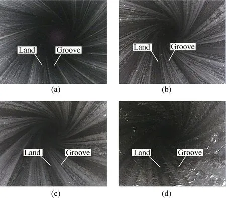
Fig.10.Endoscopies of bore damage at the terminal of areaI:(a)period 1,(b)period 2,(c)period 3,(d)period 4.

Fig.11.Endoscopies of bore damage in areaII:(a)period 1,(b)period 2,(c)period 3,(d)period 4.
The gun barrel used in current analysis is a 12.7 mm large caliber machine gun barrel. The method of bullet-barrel FEA model establishment for barrels at four life periods was developed in this section based on the mesh generation work completed in section 2.2.The assembled FEA model of barrel-bullet interaction is shown in Fig.18.

Fig.13.3D mesh generation of barrel at period 3.
2.3.1. Basic assumptions
To concentrate on the influences of bore damage upon bullet's interior ballistic performance and to construct a tractable FEA model,several assumptions were made.
(1)The barrels were assumed to be rigid.Materials for the components of bullet were assumed to be isotropic.
(2)The heat convection between bullet and propellant gas and bullet's thermal radiation were ignored.The environment temperature was set to 20°C.
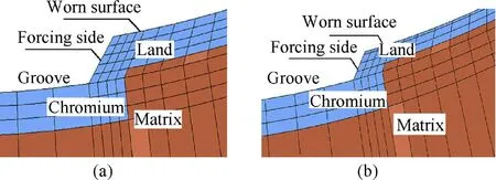
Fig.14.Mesh generation of worn chromium coating:(a)worn lighter section(b)worn heavier section.

Fig.15.Mesh generation of barrel at period 3 in areaI.
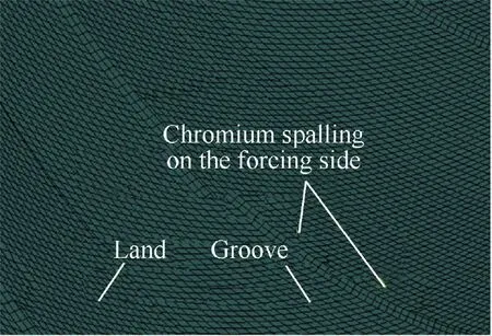
Fig.16.Mesh generation of barrel at period 3 in areaII.

Fig.17.Mesh generation of barrel at period 3 in area III and Ⅳ
(3)The recoil of the barrel and the leak of propellant gas through the clearance between bullet and barrel were ignored.
(4)The classical interior ballistics model was used to represent the uniform and simultaneous ignition of propellant charge.
2.3.2. Model properties and boundary conditions
An eight-node linear brick element C3D8RT with coupled displacement-temperature degree of freedom was adopted for structural discretization.As shown in Fig.19,the mesh for the cylindrical section of the bullet outer jacket was refined and set to 6 layers since the deformation of this part is relatively larger during the engraving process.The mesh dimension of the cylindrical part was set to 0.1 mm under the balance of calculation accuracy and time cost.
The Johnson-Cook constitutive relation model[18]was used for bullet's components.This well-known model takes strain rates and temperature into consideration in metal's plastic deformation process.The von Mises yield stress σ is expressed as Eq.(1).

Where ε and ˙ε are the effective plastic strain and the effective plastic strain rate,respectively;˙ε0is the reference strain rate;A,B,C,mandnare material constants;T,Tr,Tmare the actual temperature,room temperature and melting temperature in the absolute scale,respectively.
Johnson-Cook failure model[18]was used to judge whether there was damage in a material element or not.The damage parameter is calculated from the effective strain given as follows.

WhereD1~D5are material failure constants and σ*is the stress triaxiality.
Material element stiffness reduction is described through linear damage accumulation as follows.

WhereD(εp)is the damage variable for a material element.WhenDreaches 1,stiffness of material element equals 0 and the element is deleted.
The material's mechanical and thermal parameters of brass jacket are listed in Table 1.
General contact algorithm based on the penalty function method was used for contact between bullets and barrel.Barrel was treated as a rigid body and constrained in all degrees of freedom.The propellant gas pressure was loaded on the bottom surface of the bullet through user subroutine VUAMP.Gravity for 9.8 m/s2was also added.The friction coefficient between bullets and barrels was set to 0.01 according to Ref.[19].Two local rectangular coordinate systems were established on bullet's mass center and on a base point fixed to the ground respectively.A connector between the two coordinate systems was set in ABAQUS software to obtain bullet's moving posture by monitoring the relative motion of them.
2.3.3. Coupled mechanical-thermal FEA model
Temperature increase of bullet's material will significantly influence the interior ballistics performance according to Ref.[20],such as axial resistance,chamber pressure,muzzle velocity of bullets,etc.Accordingly,rise of bullet's temperature caused by bullet's plastic deformation and the friction at the contact interface was taken into consideration.The total temperature increase can be acquired through Eq.(4).

Fig.18.Assembled FEA model of bullet-barrel interaction.
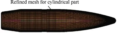
Fig.19.Diagrammatic sketch of mesh generation of bullet.

WhereTεandTfare the temperature increment caused by plastic deformation and friction,respectively;ρ is material's density;cis the specific heat capacity,σ and ε are bullet's stress and plastic strain,respectively;β is the inelastic heat fraction defined as 0.9.
2.3.4. Coupled interior ballistics calculation through user amplitude subroutine(VUAMP)
It is beneficial to obtain more accurate chamber pressure data under barrels with bore damage by coupling the calculation of interior ballistics equations and the bullet's axial motion through user subroutine provided by ABAQUS software.In order to simplify the programming work,the new interior ballistics equations,which coupled the classical interior ballistics equations[16]with the FEA methods,were divided into one main equation(Eq.(5))and four auxiliary equations(Eq.(6)).Eq.(5)was solved by the Fourth Order Runge-Kutta algorithm.

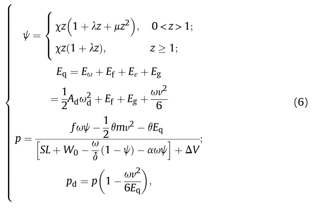
Wherezis the relative burned thickness of propellant,ψ is the relative burned volume,u1,e1andnare the constant of burning rate,the half thickness of the multiple-perforated propellant and the pressure index of burning rate,respectively,fis the propellant impetus,ω is the mass of propellant,δ is the density of propellant,α is the covolume of propellant gas.mis the mass of bullet,vis the axial velocity of bullet,Sis the cross-section area of bore,Lis the axial displacement of bullet,θ=k-1 andkis the adiabatic index,W0is the chamber volume,χ,λ and μ are the constant of propellant,Eq,Eω,Ef,EεandEgare the total secondary energy loss,the kinetic energy of rotation, the friction dissipation energy, theplastic deformation energy and the movement work for propellant gas,respectively,EfandEεare acquired by ABAQUS software,Adis bullet's polar moment of inertia,ωdis bullet's rotation velocity,pis the average chamber pressure,pdis the bullet base pressure,ΔVis the increase of chamber volume caused by bore damage,which can be obtained through Eq.(7)[9].
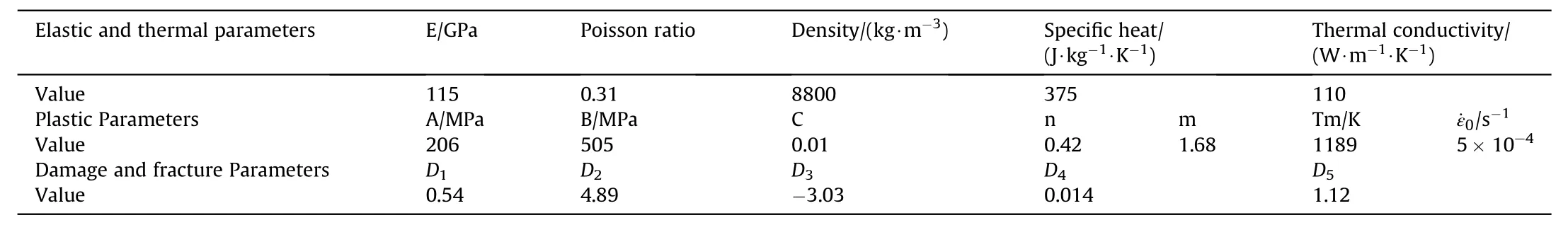
Table 1Mechanical and thermal parameters of brass jacket material.
Where N is the number of rifling,K1andKgare coefficients that depend on the structure of the land and the groove,ΔR1and ΔRgare the radius increment of the land and the groove respectively.
The user amplitude subroutine written by FORTRAN language was used to solve Eq.(5)~(7)with the assistance of explicit finite element methods as following steps.
Step 1:The ratio of relative burned thickness of propellant wasztat timet,and bullet's base pressurepd,tat this moment could be obtained by Eq. (6). Above works were conducted in user subroutine.
Step 2:As the user subroutine transmitted the base pressurepd,tto ABAQUS,pd, twas then loaded on the bottom surface of the bullet.The thrust of propellant pushed the bullet moving forward in a specified time increment Δt.At timet+Δt,the kinematic parameters such as the translational speed vt+Δt,the angular velocity ωd,t+Δt,the axial displacementLt+Δtetc,and the stress and strain of the bullet were obtained by setting sensors which are inherent in ABAQUS on the bullet.After the calculation for this specified time increment was done,the above parameters would be passed to the user subroutine.
Step 3:The bullet base pressure would get updated topd,t+Δtby substituting the parameters obtained in step 2 into the interior ballistics equations in user subroutine.Then the updated pressure was passed to ABAQUS.
Step 4:Repeat step 2 and continue the iteration until the bullet reached muzzle(L≥Lg,Lgis the bullet's maximum axial displacement in interior ballistics process).
The iteration process is illustrated in Fig.20.
2.4. Verification of the FEA model
Based on the experimental bore damage data in section 2.1 and the mesh generation method for damaged barrel proposed in section 2.2,four coupled bullet-barrel finite element models,in which the barrels had conducted 0,1400,3000 and 6000 firing cycles respectively,were established for the analysis of the interior ballistics process.As mentioned in section 2.1,the barrels at 4 life periods were numbered 1-4 with the increase of firing rounds.
The simulation results of both an undamaged barrel numbered 1 and three damaged barrels numbered 2-4 were verified with the experimental results in this section.For the first undamaged barrel,the simulated peak chamber pressure and the muzzle velocity were 328 MPa and 806 m/s,which are 2.5%and 0.75%slightly greater than experimental results,respectively.Chamber pressure curves in Fig.21 shows that the numerical results agreed well with the experimental data.The possible reason for the slight shift between the two curves is the stochastic perturbation of ammunition factors,such as the charge weight,the diameter of bullet,etc.Besides,the maximum axial resistance valued 10954 N is 8.7%smaller than the quasi-static engraving experiment as the friction coeffciient in a dynamic process is relatively smaller than that in a quasi-static process.The quasi-static engraving experiment was conducted by pushing the bullets into a stationary barrel for 60 mm with a constant speed of 15 mm/min.The thrust was provided and recorded by a material testing machine throughout the engraving process.For the three damaged barrel,the muzzle velocity results obtained through numerical and experimental methods are listed in Table 2,which are well matched.

Fig.20.The flowchart of coupled interior ballistic process.

Fig.21.Comparison of the pressure curves.
Therefore,the above verifications proved the rationality and preciseness of both the mesh generation of damaged barrel and the coupled bullet-barrel FEA model.
3. Results and discussions
3.1. Numerical simulation results and analysis
3.1.1. Influence of bore damage on the interior ballistics process
The comparison of the chamber pressure and the bullet's axial velocity profiles of the four studied barrels are presented in Fig.22.Compared with the undamaged barrel,the maximum chamber pressure of the other three barrels decreased by 1.1%(324.4 MPa),1.7%(322.3 MPa)and 4.9%(311.9 MPa)with the increase of firing rounds,while the muzzle velocity decreased by 1.2%(796 m/s),1.9%(791 m/s)and 4.8%(767 m/s),respectively.The variation trends of the maximum pressure and the muzzle velocity are shown in Fig.23.It can be seen from Fig.23 that the two parameters,which significantly reflect the interior ballistic performance,kept going down in a barrel's lifetime.More is that the barrel's interior ballistic performance did not decrease obviously in its early life.Comparatively,apparent decline of the chamber pressure and the muzzle velocity occurred in a barrel's later lifetime,which leaded to the swift arrival of a barrel's life end.
Eq.(8)and Eq.(9)are the performance predictions for this 12.7 mm machine gun derived by fitting the maximum chamber pressure(MPa)and the muzzle velocity(m/s)with the fired roundsnbased on the simulation results with Least Square Method.

The resulting pressure-displacement and axial motion resistance-displacement profiles for the four barrels with different degrees of damage are shown in Fig.24.It can be seen from the pressure-displacement curves that the peak pressure points tended to move backward.The backward displacements toward the breech of the peak point of the number 2 to 4 barrel were 1.1 mm,2.3 mm and 5.7 mm,compared with the undamaged barrel,respectively.The reason for this phenomenon is that to achieve the same propellant combustion volume behind the bullet,the bullet's axial displacement requirement keeps decreasing as the diameter of bore expands with the rise of firing rounds.Besides,the peak axial resistance decreased with the firing cycle rose and there was a decline by 20.8%(8679 N)at the life end compared with the undamaged barrel(10954 N).The peak point of the axial resistance moved forward to the muzzle from barrel 1 to barrel 4.Particularly,due to the spalling of almost the entire coating metal on bore as shown in Fig.9(d),the resistance peak value of barrel 4 appeared after the bullet moving past the forcing cone,which was different from the other three barrels.In area Ⅳ,which is called the muzzle wear area and looks like a“trumpet”,the axial resistance value presented a rapid decline.

Fig.22.Curves of bore pressure and velocity during interior ballistics process.

Fig.23.Variation trend of initial velocity and peek pressure with firing rounds.
Therefore,a probable explanation for the decline in chamber pressure and bullet's muzzle velocity for this 12.7 mm machine gun is that the damage on bore,which extends with the increase of firing rounds,enlarges the inner diameter and in turn leads to the reduction of axial resistance and the expansion of the volume behind the bullet during the interior ballistic process,which both go against the establishment of chamber pressure,and finally degenerates the interior ballistics performance.

Table 2Comparison of the muzzle velocity of damaged barrels.

Fig.24.Variation of bore pressure and motion resistance versus bullet displacement.
3.1.2. Influence of bore damage on bullet's muzzle states
The yardsticks for a barrel's life end are that the decline rate of bullet's muzzle velocity reaches 15%,or the rate of elliptical bullet hole with the ratio of long axis to short axis no less than 1.25 exceeds 50%,or the radius of the bullets'dispersion circle which includes 50%of the bullets at the range of 100 m exceeds 30 cm for three consecutive firing accuracy tests[21].The barrel life tests indicate that the major reason for the life end of the 12.7 mm machine gun is the overproof rate of elliptical bullet hole.Combined with the decline rate of muzzle velocity of barrel 4,which is 5.25%and much less than 15%,the main probable reason for the end of barrel life is the variation of bullet's muzzle states.Whether and how the bore damages influence bullet's muzzle states,which include the initial disturbances and the surface morphologies,will be discussed in this section.
3.1.2.1. Initial disturbance.Angle between the bullet axis and barrel axis symbolized by α is called the swing angle of a bullet,which varies with the swing angular velocity ˙α.Besides,angle between the bullet's mass center velocity direction and the barrel axis symbolized by β is called the deviation angle of bullet.These three parameters describe the bullet's in-bore motion posture and thus they are α0,˙α0and β0at the muzzle,which constitute the initial disturbances of the bullet[22].
Bullet's moving posture was monitored throughout the interior ballistics process,which was realized by setting a connector between bullet's mass center and ground in ABAQUS software,to acquire the initial disturbances of a bullet at the muzzle.The three initial disturbance parameters of the four barrels are listed in Table 3 and the variation trends of the initial swing angle and the initial swing angular velocity are shown in Fig.25.Bore damage had a greater impact on the initial swing angle and the initial swing angular velocity relative to the impact on the initial deviation angle.The reason for this situation may be that the initial deviation angle is to a certain extent influenced by the vibration condition of thebarrel at the muzzle.The rigid body assumption of the barrel in section 2.3.1 may slightly decrease the variation of the initial deviation angle.However,the muzzle vibration condition is determined by a coupled man-weapon system and is slightly affected by bore damage,so that the rigid body assumption of the barrel is reasonable and necessary to focus on the influence of bore damage on bullets.The initial disturbances presented a rapid increment in a barrel's later life,just like the variation rule of the muzzle velocity and the maximum chamber pressure as shown in Fig.3.This may be because that the coating chromium on bore,especially on the origin part of the rifling,had exfoliated severely in barrel's later life,which accelerated the damage expansion on the matrix steel without the protection of hard and wearproof coating chromium.The values of the initial swing angle,the initial swing angular velocity and the initial deviation angle of the barrel at life end were 2.79,3.02 and 1.48 times as large as that of an undamaged barrel,respectively.

Table 3Initial disturbance parameters of bullets.

Fig.25.Variation trend of bullet's initial disturbance parameters with firing rounds.
In addition,bullet's rotation velocity ωdis a pivotal parameter of bullet's flight stability in the exterior ballistics process according to Eq.(10)[23].

Where σ is the stability coefficient,Bdis the equatorial moment of inertia,Adis the polar moment of inertia,βdis the pitching moment coefficient.The flight stability keeps well when 0<σ<1,and becomes better when the value of σ increases.
As the rotation velocity directly depends on bullet's axial velocity,the dimensionless process is carried out through Eq.(11)to eliminate the influence of velocity variances of four barrels.

Where ωd1is the dimensionless rotation velocity,dis the bullet diameter.The theoretical value of ωd1is 0.215 according to the twist degree of the rifling.
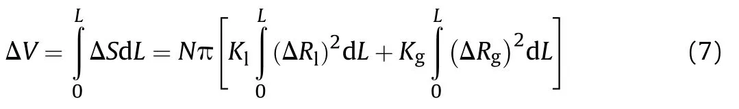
The dimensionless rotation velocities of 4 barrels in the region close to the muzzle are illustrated in Fig.26,and the average values and the standard deviations of them are listed in Table 4.With the increase of firing rounds,the value of bullet's rotation velocity became smaller and the fluctuation of rotation velocity got larger.Both of them are detrimental to bullet's flight stability and in turn increase the rate of elliptical bullet hole.
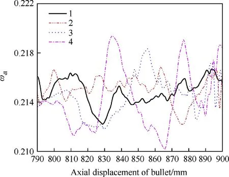
Fig.26.Dimensionless rotational velocity near the muzzle.

Table 4Average value and standard deviation of dimensionless rotational velocity.
3.1.2.2. Surface morphology.Comparisons of bullet's surface morphologies of 4 barrels at different life periods just after engraving and at the muzzle are presented in Fig.27 and Fig.28,respectively.The images of collected bullets fired by undamaged barrel and endto-life barrel in the barrel life test are displayed in Fig.29.The simulation and experimental size data of the grooves on bullets'surfaces extruded by the land of rifling at these two moments are listed in Table 5 in two lines,which is convenient for comparison of the groove size variation between these two moments.The data just after engraving are listed in the first line and the data at the muzzle locate at the second line in parentheses.
Fig.27 and Table 5 show that owing to the increasing degree of wear on bore, the sizes of grooves on bullet's surface kept decreasing along with a barrel's lifetime.The two sides of the grooves on bullets'surfaces for barrel 2 to 4 presented an obvious asymmetry after engraving,and the forced side,which is the inferior side of a groove shown in Fig.27,was much shallower as a result of that the forcing side of the forcing cone was worn much more seriously.The uneven local ablation craters and spalling of coating chromium on the forcing cone of bore brought irregularly distributed local notches to the surface of the bullet.With the motion of bullet along the barrel going on,the bullet's groove sizes of barrel 2 to 4 were approaching those of barrel 1 when comparing the groove sizes data at the muzzle with those after engraving in Table 5.The reason for this phenomenon is that the damage of a barrel in area II to area Ⅳwas much lighter than the damage in areaI.The sizes of the grooves on bullets'surfaces for the damaged three barrels increased and thus the gap of the groove sizes with barrel 1 got narrowed at the muzzle.The influence of damages,especially the damage of the second type,on bullet's surface morphology became larger with the increase of bullet's axial velocity and displacement,as the integrity of the bullet surface and the regularity of the groove at the muzzle were much worse than those after engraving as shown in Fig.28.It becomes especially obvious when comparing Fig.28(a)and(d)that the bullet's surface morphology of a barrel at the life end changed a lot from that of an undamaged barrel, which would significantly change bullet's aerodynamic parameters and thus would decrease the exterior ballistics performance.It can be seen from Fig.29 that the grooves on the collected bullet shot by end-to-life barrel is much shallower than those on the collected bullet shot by undamaged barrel.Besides,there are irregularly distributed local notches on the surface of the collected bullet shot by end-to-life barrel,which is the same as the simulation results.Furthermore,the groove size data of the experimentally collected bullets shot by undamaged barrel and end-to-life barrel present high consistency with the simulated groove size data of the bullets shot by barrel 1 and barrel 4 at the muzzle according to Table 5.Therefore,the change of surface morphology is an important reason for the end of this 12.7 mm machine gun's life.
3.2. Conclusions
The distribution and evolution rule of the damage of a 12.7 mm machine gun barrel were concluded form a series of barrel life tests in this study.Based on that,a mesh generation method for barrels with real bore damage was developed.In addition to taking the thermal properties of bullet and the gas pressure loaded from user subroutine into consideration,a finite element numerical study about the influence of the damage of barrel on the interior ballistics performances and muzzle states was conducted.The following conclusions can be drawn based on the simulation results.

Fig.27.Bullet's surface morphology after engraving:(a)period 1,(b)period 2,(c)period 3,(d)period 4.
Fig.28.Bullet's surface morphology at muzzle:(a)period 1,(b)period 2,(c)period 3,(d)period 4.

Fig.29.Images of bullets in the life test:(a)fired by undamaged barrel,(b)fired by end-to-life barrel.
(1)The mesh generation method which was based on the distribution and evolution rule of the bore damage can be regarded as a precise way to construct finite element mesh of the real damaged barrel as the simulation results agreed well with the experimental results.
(2)The interior ballistics performance parameters,such as the muzzle velocity and the maximum chamber pressure,and the bullet's initial disturbances,such as the initial swing angle and the initial swing angular velocity,would greatly decline in the later life for this machine gun barrel,which leaded to the sudden end of the barrel in its later life.
(3)The drop of bullet's flight stability caused by the reduction of its rotation velocity together with the variation of bullet's aerodynamic parameters caused by the change of its surface morphology would cause significant change of bullet's exterior ballistics performance.
(4)The increase of bullet's muzzle disturbance and the change of bullet's surface morphology caused by bore damage are the main reasons for the life end of this machine gun barrel since the decline rate of muzzle velocity is far less than the threshold of 15%.
The real bore damage form is no doubt too complicated to reappear through finite element method,and there may be oversimplifications in damage form and propellant combustion characteristics in the current study.This can partly explain the slight discrepancy between numerical and experimental results in this study.Further work is to incorporate the model with the two-phase flow interior ballistics model and the application of the obtained results to other gun barrels with different caliber.

Table 5Comparison of groove size of bullet.
Conflicts of interest
The authors declare that there is no conflict of interests regarding the publication of this paper.
Acknowledgement
The study was supported by the National Natural Science Foundation of China(grant number 11802138),the China Postdoctoral Science Foundation(grant number 2018T110503),and the Fundamental Research Funds for the Central Universities(grant number 30918011302).

- Defence Technology的其它文章
- Round robin using the depth of penetration test method on an armour grade alumina
- Sonochemically assisted synthesis of nano HMX
- Effect of particle gradation of aluminum on the explosion field pressure and temperature of RDX-based explosives in vacuum and air atmosphere
- FEM analysis and experimental investigation of force and chip formation on hot turning of Inconel 625
- Study on liquid-filled structure target with shaped charge vertical penetration
- Thermal decomposition of ammonium perchlorate catalyzed with CuO nanoparticles