Pedestrian positioning system based on combined inertial positioning and simplified indoor geographic information system
2020-01-07 08:20LIUYuTANGJiawanLIJunlinLUYongleFANGZhenLIXinghaiChongqingEngineeringResearchCenterofIntelligentSensingTechnologyandMicrosystemChongqing
中国惯性技术学报 2019年5期
LIU Yu,TANG Jiawan,LI Junlin,LU Yongle,FANG Zhen,LI Xinghai(.Chongqing Engineering Research Center of Intelligent Sensing Technology and Microsystem,Chongqing
University of Post and Telecommunications,Chongqing 400065,China
2.China Electronic Technology Group Corporation Twenty-sixth Research Institute,Chongqing 400065,China)
Abstract:The error of the inertial positioning system (IPS) will accumulate over time,which makes the IPS unable to be used for a long time.In indoor geographic information system (Indoor-GIS),the geographic information of buildings and landmarks can be used to modify and optimize the inertial positioning algorithm which can effectively compensate the accumulated error.Thus,the accuracy of IPS can be improved and the service time of the system also can be extended.Radio frequency identification(RFID) system and building structure information were used to construct a simplified Indoor-GIS.At the same time based on Indoor-GIS,an enhanced Pedestrian Dead Reckoning (PDR) algorithm was proposed to integrate Indoor-GIS and IPS.Experiments has proved that the pedestrian positioning system based on inertial and Indoor-GIS had better performance than the system based on inertial only.When the landmarks in Indoor-GIS had function of heading-calibration or coefficient-calibration of step length estimation formula,the error of system integrating Indoor-GIS could be reduced by 50% or 67% compared with the traditional IPS after 60 min; When the landmarks in Indoor-GIS had functions of height-calibration and position-calibration,the error of system integrating Indoor-GIS did not increase significantly over time,even after more than 150 min of use,the error remained within 2m (>80% probability).
Key words:pedestrian positioning; inertial positioning; radio frequency identification; pedestrian dead reckoning; indoor geographic information system
In modern society,the cities’ building structures and traffic are becoming more and more complicated.How to accurately locate pedestrians in a complex environment becomes a research hotspot in the field of positioning.Inertial positioning technology can achieve autonomous positioning without relying on external signals,and has broad application prospects in the field of pedestrian positioning.However,inertial positioning system (IPS)cannot be used for a long time because of its accumulated errors.Many researchers have done a lot of work on the accumulated error compensation of IPS[1-2].Geographic information system (GIS) is a technical system that collects,stores,manages,calculates,analyzes,displays and describes the geographically distributed data of the whole or part of the Earth’s surface (including atmosphere) under the support of computers’ hardware and software systems.GIS is an inter-discipline that combines geography,cartography,remote sensing,and computer science and it has been widely used in different fields.
In recent years,many scholars have begun to study the construction of indoor GIS and expanded its application fields[3-5].Some of them have combined GIS with IPS to achieve indoor positioning and real-time navigation.For example,Li C C[6]have proposed a building/environment data and information system (BeDIS)which can provide people with sufficiently accurate location data in large buildings.The core component of BeDIS is BeDi mist that is a virtual repository of data and information on the building,interior layouts and facilities.Therefore,BeDi mist can be considered as an indoor GIS.Yu C[7]used the map-aiding method and map-matching method to constrain the primary Wi-Fi/IMU-derived position through an Auxiliary Value Particle Filter (AVPF),which can effectively reduce the accumulation of positioning errors of a stand-alone inertial navigation system.Although this algorithm optimized the positioning effect,it has strong dependence on the map and WIFI positioning system.Therefore,the advantage of autonomy of IPS did not be fully exploited.
Aiming at the accumulation errors problems in the traditional IGS,this paper proposed and studied a pedestrian positioning system based on inertial and simplified Indoor-GIS.The Radio Frequency Identification (RFID) system and the building structure information were used to construct a simplified Indoor-GIS system,in which the RFID tags served as landmarks which had functions of position calibration,heading calibration,and altitude calibration.The pedestrian positioning system based on inertial and simplified Indoor-IS can compensate the accumulated error of the IPS with the help of some external devices,and finally realize the long-term use of the IPS.
1 PDR algorithm
The PDR algorithm is the most widely used in inertial pedestrian positioning.The principle of the PDR is to calculate the pedestrian position by using pedesian’s step length and heading.Here,the walking step count obtained by the step detection algorithm was defined as k; the step length of the pedestrian at kth step was defined as Lk; the heading of the pedestrian obtained by gyroscope,magnetometer and other devices was defined as φk.Then the position (xk,yk)of the pedestrian can be calculated by the formula (1).

The process of the PDR algorithm generally includes three core steps:step detection,step length estimation,and attitude calculation.Usually the PDR algorithm obtains a two-dimensional position,if adding a barometer in IPS,the pedestrian’s height can be got,hence a three-dimensional position can be realized.Several key sub-algorithms are described below.
1.1 Step detection
When the accelerometer is located at the waist of pedestrian,the basic step detection methods include peak detection method,zero-crossing detection method and so on,but detecting a single data feature is prone to misjudgment.Hence the commonly used step detection method always detects multiple data features in a single step cycle.In this paper,the peak-valley determination is used to detect the step,and the thresholds are added to reduce the misjudgment rate.Experimental results veryed that the accuracy of this step determination method can reach more than 98%.
1.2 Step-length estimate
When pedestrian walking,the length of each step is not a fixed value,but a dynamically changed one.The step length is generally related to many factors such as walking speed,stride frequency,pedestrian height and so on.Researchers have proposed a variety of step length calculation models[8-10],of which the single-parameter empirical model[11]is the most widely used.The model is shown in formula (2).
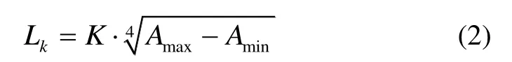
Where Amaxand Aminrepresent the maximum and minimum value of the acceleration modulus for each step respectively,and K is a constant for unit conversion.In the actual use of the algorithm,the K value generally takes the ratio of the real step length to the estimated step length.The single-parameter empirical model is simply to calculate and can be easily combined with the peakvalley step detection algorithms.However,when using this model in PDR algorithm,the value of K has a great influence on the accuracy.How to obtain the reasonable value of K is one of the research focuses in this paper.
1.3 Attitude algorithm
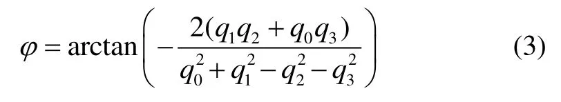
In the IPS,the commonly used attitude algorithms include Euler angle method,quaternion method,and direction cosine matrix method.The Euler angle method exists the phenomenon of locking the universal joint,so it is difficult to realize the full attitude calculation.The direction cosine matrix method has high computational complexity and low efficiency.The quaternion method is simplified and widely used in the pedestrian positioning algorithm.In this paper the quaternion method based on extended Kalman Filter was used.The quaternion in the carrier coordinate transformation is used as the state vector,and the normalized three-axis accelerometer value akand the three-axis magnetometer value mkare used as observation vector to construct a Kalman Filter equation.Finally,the heading angle of the carrier is obtained by the updated quaternion (q0,q1,q2,q3)according formula (3).
1.4 Height calculation
The addition of a barometer in the pedestrian IPS can collect the height of the pedestrian and finally realize three-dimensional positioning.In this paper,the barometric pressure data was collected and filtered by Mean Filter.The height value relative to the standard barometric pressure is calculated according to formula (4).

Where P is the mean value of atmospheric pressure within 0.5 s.
The initial height value H0is calculated by taking the atmospheric pressure data within 2 s after starting-up.The real-time solution height of the barometer was defined as h,and the final output height value Hkcould be calculated according to formula (5).

Where Δis a threshold value for eliminating the sudden jump of height data.
2 Construction of simplified indoor-GIS
The Indoor-GIS system uses computers and other technologies to restore and display the indoor environment with high precision and fineness.The process of constructing a complete GIS system is very complicated.The focus of this paper is on the optimization of GIS for IPS,so the construction of the complete GIS couldn’t be discussed here.Researchers have proposed that the building structure information in GIS could constrain the heading in the PDR algorithm[12].However,during the experiment,it was found that relying only on the structural information of buildings may lead to some heading miscalculations,thus causing the error divergence of the inertial positioning algorithm.On this basis,this paper proposed a method of constructing landmarks using wireless communication systems.A simplified Indoor-GIS could be constructed using these landmarks and building structure information.On the one hand,the indoor-GIS could eliminate the miscalculation because it builds indoor geographic information system by using RFID instead of just relying on building information that will cause course misjudgment.On the other hand,it could further strengthen the correction and compensation for the inertial positioning algorithm through the geographical information of landmarks.Choosing RF signal source as the marking point can effectively eliminate the accumulated error of inertial sensor with time.However,this method needs lay out auxiliary equipment in advance,which will limit the practical application.
Building structure information can be obtained directly from the building plan.In the simplified GIS proposed in this paper,it was not necessary to digitize these maps to form a computer software or database,but was to use simple analysis of those maps as the basis for setting landmarks.Quantified building structure information was store in landmarks,and that information would be fed back to the IPS at the appropriate time and participate in the calculation of the PDR algorithm.In this paper,the RFID system was used to construct landmarks system.
The core function of the RFID system is“identification”,that is,the RFID tag reader can read the data stored in the tag to realize the identification of tag.The RFID tags were used as landmarks,and the geographical information of the landmarks is written in the tag as calibration data.Those tags could be recognized by a RFID reader which could realize a combination of simple GIS and IPS.The recognition distance of low-frequency RFID is generally 0~30cm,which is invalid for the tag reader fixed at waist.So it is necessary to select a high-frequency RFID system that can reach the meter level.UHF RFID’s recognition distance ranges from a few meters to tens of meters.If calibration is carried out at a distance of more than ten meters,the accuracy of inertial positioning obviously cannot be improved.In this paper,RFID identification chip and ceramic antenna of Guangzhou Cells-net Electronic Technology Co.,Ltd.were adopted to match the UHF passive tag.The maximum recognition distance of the tag was tested under different antenna transmitting powers.According to the experimental results,the transmitting power of the antenna was set to 20 mW.Under this power,the maximum recognition distance of the tag is about 1 m.
Three types of RFID calibration tags were placed in the positioning scene as landmark points,and the functions and stored data are shown in Table 1.
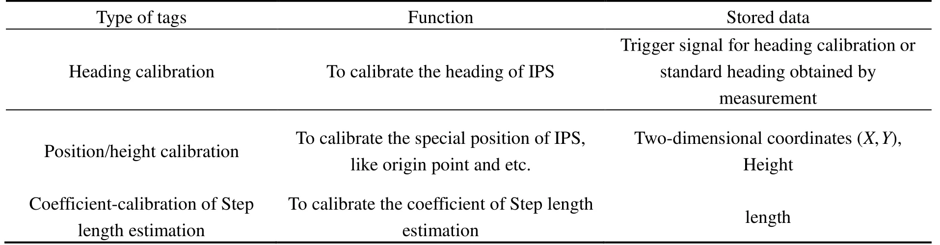
Tab.1 The functions and stored data of three types of RFID calibration tags
The advantage of IPS lies in its autonomy.The integration of Indoor-GIS system in the IPS actually destroyed the autonomy of IPS.According to the building structure information,the landmarks should be placed reasonably,and the number of landmarks should be reduced as much as possible to simplify the GIS,which can decrease the damage to the autonomy of inertial position system.
Generally,the buildings structure is square and the width of the internal corridor is 1~2 m.Meanwhile,the corners of the corridor are mostly right angles.In this paper,a simplified building structure was used as the basis for the research of tags placement strategy.In other complex environments,this simplified structure can be referred,or analogous structure can be found.
Figure 1 shows a simplified plan view of the floor.A Cartesian coordinate system was established according to the following rules:setting the pedestrian’s starting point O as the origin,the pedestrian’s forward direction as the positive direction of X-axis,the direction perpendicular to the pedestrian’s forward direction as the positive direction of Y-axis,and the direction parallel to the pedestrian’s body as positive direction of Z-axis.The angle of the pedestrian’s initial heading direction OA was defined as φ0.According to walking habit of pedestrians,when pedestrians walk in the corridor,the heading is generally along the corridor direction or against the corridor direction.Therefore,the heading angle of the pedestrians walking in the corridors along three direction of AB,BC and CD can be calculated based on the initial heading φ0,as shown in Equation (6):
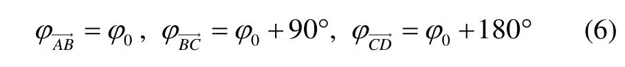
So,the heading calibration tags can be placed in the corridor,such as point H in Figure 1.When the pedestrian passes those tags,the current accurate heading of the pedestrian can be calculated according to the initial heading φ0.When placing tags in non-vertical corridors,the inclination angle of the corridor needs to be measured and write into the tags,such as point I on the corridorin Figure 1.
At the same time,the heading calibration tags and position calibration tags can be placed in the corridor.Taking the starting point as the origin,the exact coordinates of a point can be obtained through measurement.For example,a tag is placed at point B,when the pedestrian walks through this tag,the tag reader will read the exact position (xB,yB)and then write it into tag to calibrate the location.

Fig.1 A simplified plan view of the floor
In Figure 1,points E and F are not in the corridor,and it is impossible to restrict the heading of pedestrians through the corridor,but these two points can be used as position calibration points.In the IPS,the pedestrian position can be accurately obtained when pedestrian walk normally.However,if the pedestrian appears “lateral walk”,“piaffe”,“backward” and other states when walking,it will seriously affect the positioning accuracy.The above situations will often occur when the pedestrian positioning system is applied in practice.For example,in a factory,workers move back and forth around their stations or machines,which can cause the IPS to drift greatly in a short period of time.In order to avoid this phenomenon,position calibration is necessary and these special points are the preferred location for position calibration.The height-calibrated label can be placed anywhere on the floor,but it is best placed where the pedestrian passes,as shown in Figure 1 near point A of the bathroom.
The height-calibrated tag can be placed anywhere on the floor,but it should be best placed where the pedestrians often pass,such as point G near the bathroom as shown in Figure 1.
The coefficient-calibrated tag of the step estimation formula should be placed at a point that the pedestrian can reach straightly,such as point B in Figure 1.A tag in which the distanceofwas written will be placed at point B.Distanceand the corresponding step number can be used to calculate the real step length,and it can be substituted into formula (2) to solve K value.When the pedestrian walk straightly through point B,the coefficient-calibration can be triggered.After passing point B,pedestrians can walk freely.
3 Improved PDR algorithm based on simplified Indoor-GIS
RFID positioning technology uses radio frequency to exchange data in non-contact two-way communication,that can realize identification and positioning of mobile device.Meanwhile,it can realize centimeterlevel positioning accuracy in a few milliseconds,and the transmission range is large but the cost is low.When the RFID detects the calibration tag,the data in the tag will be input into the CPU,and the course/position data outputted by the tag will participate in the PDR algorithm solution.The flow chart of the algorithm is shown in Fig.2.
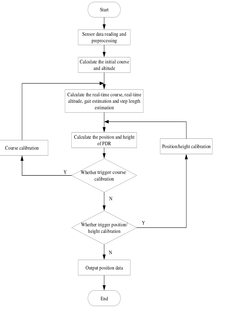
Fig.2 Fusion algorithm diagram
Based on the traditional PDR algorithm,the improved algorithm added a heading calibration algorithm and a position calibration algorithm.The two sub-algorithms were described below.
3.1 Heading-calibration algorithm
The pedestrian’s initial heading φ0will be recorded when the positioning system begins to be used.According to the initial heading,four directions,,,andcan be obtained by formula (7),which are parallel or perpendicular to the initial heading.

When a pedestrian passes a heading-calibration tag placed in a corridor that is perpendicular or parallel to the initial heading,the heading Φwhich is used in PDR algorithm is obtained by Equation (8).Where φis the real-time heading obtained by the EKF attitude algorithm,and Δis the allowable deviation between the real-time heading and the true heading.

When a pedestrian passes a heading-calibration tag on a non-vertical corridor,the heading data written in the tag will be directly read by the RFID reader to be used in PDR algorithm.
3.2 Position and height calibration algorithm
In the IPS,the position of pedestrian could be expressed as (x,y,h),and the calibration data read from the RFID tag was defined as (x′,y ′,h′).When no position calibration occurs,the pedestrian position was calculated based on formula (1).When the position calibration triggered,the calibration position (x′,y′)directly output,meanwhile,this position was taken asand substituted into formula (1) to participate in the next position calculation.
Similarly,when no height calibration was triggered,the height h was calculated according to Equation (5).When the height calibration triggered,the calibration height h′is directly outputted,and this data also would be brought into Equation (5) to join the next calculation.
4 Experiment
In this paper,several sets of experiments were designed to verify the feasibility of the study.In these experiments,the landmarks were set as little as possible to reduce the influence on the autonomy of the IPS.
4.1 Experimental scenarios and verification indicators
The first teaching building of Chongqing University of Posts and Telecommunications was selected as experimental site.There are four floors,the floor height is 3.5 m,and the north-south corridor is about 70 m long.Except the first floor,the structure of the other three floors is similar.Fig.3 shows the second-floor plan of this teaching building.The width of corridor is 2 m and the corridor junction is right angle.In Fig.3,the point O was selected as the starting point of the pedestrian,and φ0was the initial walking direction.Some parameters of sensors used in this experiment are shown in Table 2.
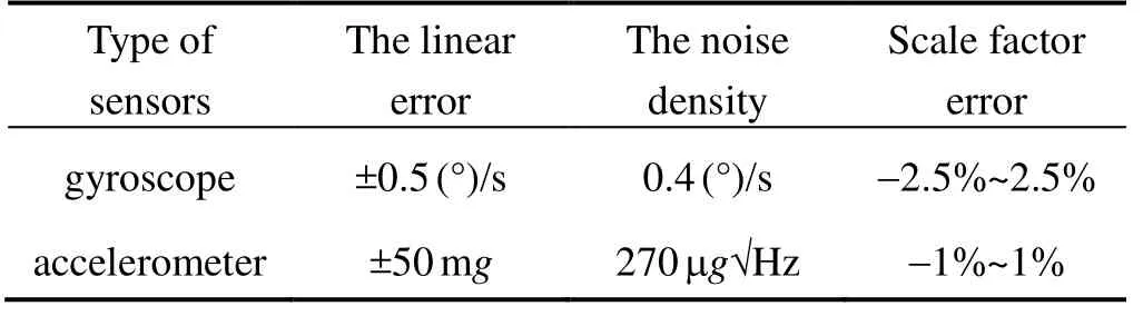
Tab.2 Some parameters of sensors
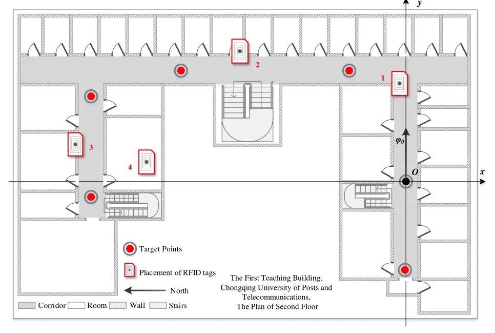
Fig.3 The 2nd-floor plan of teaching building 1 of Chongqing University of Posts and Telecommunications.
The test standard has two aspects:
1) Positioning accuracy of selected points.In the experimental scene,point O was selected as the starting point,and 10 red points on different floors were selected as the target point.The theoretical position of the target point was obtained by measurement.When the pedestrian carrying the positioning device reached 10 target points,the measurement position could be obtained,and then the distance between the measured position and the theoretical position is calculated as the positioning error.
2) Matching degree of pedestrian trajectory.The positioning system realized by the PDR algorithm can visually see the accuracy of the positioning system through measuring the comparison between the measured trajectory and the theoretical trajectory.
The accuracy of the IPS can be determined by the offset value between the measurement trajectory and the theoretical trajectory.
Trajectory matching degree is equal to the distance of path where the measurement trajectory approximately coincides with the true trajectory divided by the total distance where the criterion of approximate coincidence is that the measurement trajectory appears within ±Δmof the real trajectory.
4.2 Process of experiment
Experiment 1:
In this experiment,no landmarks were set in the teaching building.
Experimental procedure:the tester carrying the IPS walked in the teaching building according to the designated route.When the tester passed 10 target points,the positioning result is recorded to calculate the error.The tester then returned to the origin,sat down for a period of time,and after half an hour; repeated the above process until got four sets of positioning data which were the positioning accuracy of the system at the initial stage,after 30 min,after 60 min,and after 90 min.
During the test,the motion trajectory data were saved to calculate trajectory matching degree.
Experiment 2:
Three heading-calibration tags were placed at designated locations on the second,third and fourth floors of the teaching building.
The experimental procedure is the same as experiment 1.
Experiment 3:
Three position-calibration tags are placed at designated locations on the second,third and fourth floors of the teaching building.Those tags were used as heightcalibration tags.The experimental procedure is the same as Experiment 1.
Experiment 4:
The coefficient-calibrated tag of the step estimation formula was placed at the position 1 on the second floor of the teaching building shown in Fig.3.The experimental procedure is the same as Experiment 1.
4.3 Experimental results and conclusions
According to the four sets of experimental data,we can get the pedestrian motion trajectory shown in Fig.4,where the blue point indicated the position data collected in the experiment,the red line represented the theoretical motion trajectory,and the area defined by the magenta dotted line was the error range from the standard trajectory curve ±2m,which was used to assist in calculating the trajectory matching degree.The data was processed to obtain a trajectory matching degree curve shown in Fig.5.A positioning accuracy comparison curve at target points was shown in Fig.6,and a comparison chart (front view) of the pedestrian trajectories of Experiment 1 and Experiment 3 was shown in Fig.7.
The accuracy of the PDR algorithm depends on the accuracy of the heading,step length and height.At the same time,it also was affected by the cumulative error.In the first experiment,after the experiment exceeded 90 min,the pedestrian trajectory was far from the theoretical trajectory due to the wrong calculation of the heading,the average error of target points reached 6.68 m,and the maximum error reached 13.55 m,as shown in Fig.6.According to the trajectory matching degree curve in Fig.5,it can be intuitively seen that the accuracy of the traditional PDR algorithm was gradually reduced as the increase of device usage time.Even though in the absence of a heading calculation error,the shape of the measurement trajectory in the later stage of the experiment was still similar to the theoretical trajectory,and the deviation from the theoretical trajectory was getting larger.According to the large amount of data in the research process,the reason for the error the heading solution may be:when the pedestrian was turning around,the phenolmenon of “understeer”might occur during the heading calculation,that is,the measured steering angle is smaller than the actual angle,which lead to errors if the pedestrian’s trajectory continues to drift in one direction.

Fig.4 Pedestrian motion trajectory in four experiments
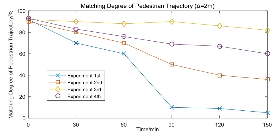
Fig.5 Curves of matching degree of pedestrian trajectory

Fig.6 Comparison curve of positioning errors at target points
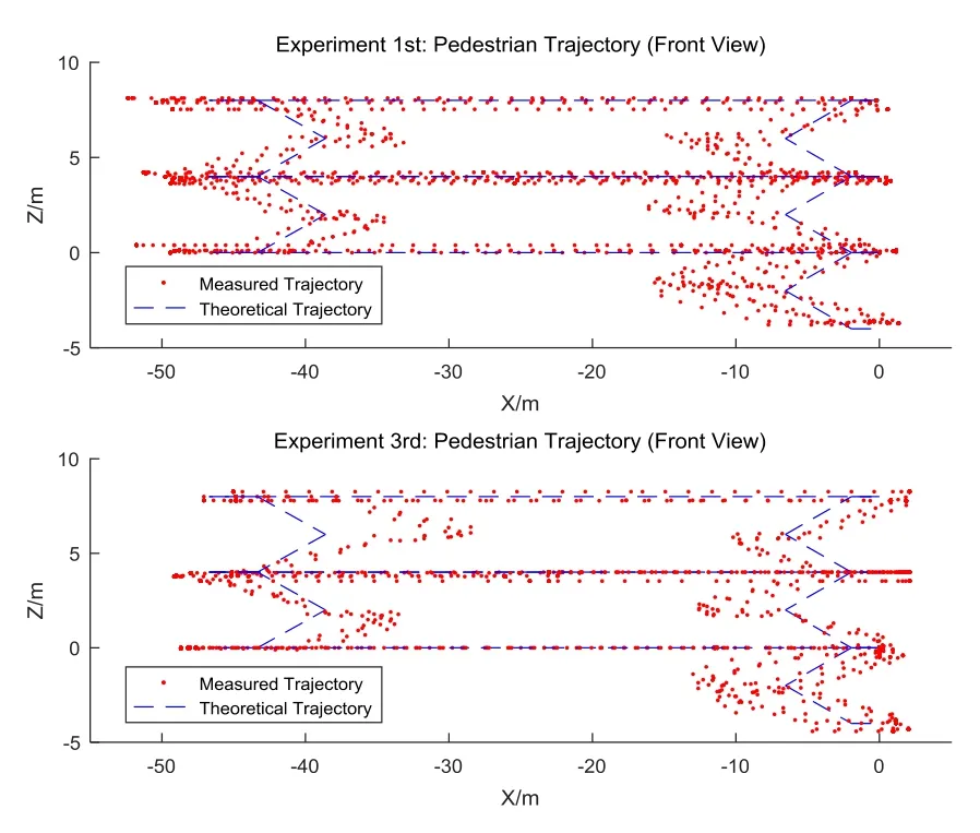
Fig.7 Comparison chart (front view) of the pedestrian trajectory of Experiment 1 and Experiment 3
In the second experiment,no wrong calculation of heading occurred during the whole experiment due to use of the heading calibration algorithm.Although the problem of “cumulative error” did not be solved by adding heading calculation into PDR algorithm,the accuracy of the PDR algorithm has been effectively improved.As shown in Fig.6,after 60 min,the error of Experiment 2 was reduced by 50% compared to Experiment 1.The same conclusion was also reflected in the experiment 4 and 1.The error of the experiment 4,in which the coefficient-calibrated tag of the step estimation formula was used,was reduced by 67% compared with the experiment 1st after 60 min.
The trajectory matching degree and accuracy of Experiment 3 were better than that of other experiments,and using the position-calibration algorithm effectively solved the cumulative error of the traditional PDR algorithm.As can be seen from Fig.5 and Fig.6,the trajectory matching degree did not decrease with time,and the position error of target points did not increase with time too.After 150 min,the positioning error in Experiment 3 was still stable within 2m (>80% probability).
The front view of pedestrian motion trajectory diagram in Experiment 1 and Experiment 3 was compared,as shown in Fig.7.It can be seen that the barometer could accurately obtain the height data,but the data has a large jumping range.If the height was calibrated,the height data could be concentrated near the theoretical value.
5 Summary
In this paper,RFID system and building structure information were used to construct a simplified Indoor-GIS,and an enhanced PDR algorithm based on Indoor-GIS was proposed to integrate GIS and IPS.Experiment results prove that the pedestrian positioning system based on inertial and Indoor-GIS had better performance than the system based on inertial only.When the landmarks in Indoor-GIS had function of heading-calibration or coefficient-calibration of step length estimation formula,the error of system integrating Indoor-GIS could be reduced by 50% or 67% compared with the traditional IPS after 60 min; When the landmarks in Indoor-GIS had functions of height-calibration and position-calibration,the error of system integrating Indoor-GIS did not increase significantly over time,even after more than 150 min of use,the error remained within 2m (>80% probability).
In addition,although it is easy to construct a simplified GIS system using RFID tags,the identification distance of RFID tags cannot be precisely controlled,which will inevitably bring new errors into the system.In the subsequent research,solving those problems will be the focus.