
Effect of the amount of trapped particulate matter on diesel particulate filter regeneration performance using nonthermal plasma assisted by exhaust waste heat
2020-01-10 07:40YunxiSHI施蕴曦YixiCAI蔡忆昔XiaohuaLI李小华XiaoyuPU濮晓宇NanZHAO赵楠andWeikaiWANG王为凯
Plasma Science and Technology 2020年1期
Yunxi SHI (施蕴曦), Yixi CAI (蔡忆昔), Xiaohua LI (李小华),Xiaoyu PU (濮晓宇), Nan ZHAO (赵楠) and Weikai WANG (王为凯)
School of Automotive and Traffic Engineering, Jiangsu University, Zhenjiang 212013, People's Republic of China
Abstract An experimental system of diesel particulate filter(DPF)regeneration using non-thermal plasma(NTP)technology assisted by exhaust waste heat was conducted and regeneration experiments of DPFs with different amounts of trapped particulate matter (PM) were conducted. The concentrations of the PM decomposition products(COx)and the internal temperature of the DPF were monitored to determine the performance of DPF regeneration and thermal safety of the NTP technology.The results showed that the concentrations of CO and CO2 and the mass of PM decomposition increased with the increase in the amount of captured PM, whereas the concentration of the NTP active substance(O3)escaping from the DPF decreased under the same working conditions of the NTP injection system.A higher amount of captured PM promoted the oxidative decomposition reaction between NTP and PM and improved the utilization rate of the NTP active substances. The peak temperature at the same measuring point inside the DPF generally increased and the phases of the peak temperature were delayed as the amount of captured PM increased. The temperature peaks and temperature gradients during the DPF regeneration process were far lower than the failure limit value, which indicates that NTP regeneration technology has good thermal durability and increases the service life of the DPF.
Keywords: diesel, diesel particulate filter, regeneration, particulate matter, non-thermal plasma(Some figures may appear in colour only in the online journal)
1. Introduction
Diesel particulate filter (DPF) can effectively reduce the amount of particulate matter (PM) in the exhaust gas; it is installed in the exhaust system of a diesel engine and is considered the most effective after-treatment measure to reduce diesel PM emissions[1-3].The most common design structure of DPF is the wall-flow honeycomb structure,which has a large number of parallel small holes in the axial direction. In the adjacent filtering channels, one of the two ends is blocked. The exhaust flows through the wall of the DPF channel and flows out from the adjacent channel so that PM is deposited on the filter wall surface. However, the continuous deposition of particles will cause blockage of DPF, resulting in increased exhaust backpressure and increased fuel consumption.Accordingly, the timely removal of PM deposited in the DPF and DPF regeneration are key technologies [4, 5].
The main DPF regeneration technologies include thermal regeneration[6,7],catalytic regeneration[8],and continuous regeneration [9]. The temperature of thermal regeneration is generally required to reach above 600°C, and the DPF regeneration process is prone to excessive thermal shock,leading to high energy consumption, high cost, and heat damage of the carrier structure. Catalytic regeneration can reduce the regeneration temperature of DPF to 200°C-400°C by coating the catalyst in DPF or doping the catalyst in the fuel. However, repeated coating and addition of catalyst are required, which complicates the operation and results in problems such as incomplete regeneration of DPF. Continuous regeneration is affected by the characteristics of the diesel oxidation catalyst,but it is influenced by the fuel spray characteristics, fuel injection pressure, fuel injection amount of the injector, and other factors. Therefore, the control strategy has high requirements. It is evident that the traditional regeneration methods have several disadvantages.
Non-thermal plasma(NTP)technology has been adopted as a new method for the treatment of industrial pollutants and has broad application prospects in diesel after-treatment systems [10-13]. The NTP active substances are generated by gas discharge ionization, which activates chemical reactions that cannot be initiated under normal conditions. Huang et al[14]used an integrated NTP catalytic reactor to purify engine exhaust and discovered that NO2catalyzed the adsorption in the NTP generator and had a significant effect on the oxidation of the soluble organic fraction (SOF) components in the PM; the ionization process reduced the light-off temperature of the dry soot (DS) component. Yao et al [15-17] used a non-homogeneous dielectric barrier discharge (DBD) NTP generator to treat diesel PM emissions;when the gas gap was 0.4 mm and the power was 300 W, the NTP generator achieved a PM removal efficiency of 67%. Okubo et al[18-20] conducted the DPF online and offline regenerations by using an NTP generator with air and NO to simulate diesel exhaust. The results suggested that the concentration of CO and CO2increased after introducing the NTP active substance; sixty percent of NO2was converted to NO and the regeneration of DPF was achieved below 300°C. Kuwahara et al [21, 22] used indirect plasma technology to conduct a DPF regeneration test on a marine diesel engine.The exhaust passing through the DPF was about 3%-5% of the total exhaust of the engine. The results proved that continuous regeneration could be achieved and the renewable energy consumption was 5% of the total electric power of the diesel engine. This research demonstrated that NTP technology can effectively decompose PM in the exhaust gas, reducing the regeneration temperature of the DPF significantly (≤300°C)without a catalyst. NTP technology provides a new research approach for DPF regeneration.
NTP regeneration technology significantly reduces the regeneration temperature of the DPF but it is necessary for the external heating source to reach the DPF initial regeneration temperature. Furthermore, most researchers have conducted regeneration experiments of DPF through simulated gas or exhaust tributaries and these conditions are far removed from the practical applications of NTP technology.In our previous research, the DPF to be regenerated was placed into a thermostat which provided the heat needed to trigger the regeneration reaction of DPF [23-25]. In order to further simplify the device and promote the practical application of NTP regeneration technology,the exhaust waste heat of the engine was used to provide the heat needed for DPF regeneration reaction in this study. The exhaust temperature of the engine is usually above 350°C and the DPF internal temperature will rise due to heating by the high-temperature exhaust gas during the operation. The DPF gradually cools from a high-temperature state after the engine has stopped.The residual heat after the shutdown is used in NTP regeneration technology,which is conducive to saving energy, simplifying the device, and promoting the application of NTP regeneration technology.
An experimental system of DPF regeneration using NTP assisted by waste heat exhaust was developed in this study.The self-heating of DPF was used as the heat source for DPF regeneration and regeneration tests of DPF with different amounts of captured PM were conducted.The concentrations of CO and CO2and the internal temperature in DPF were measured to determine the regeneration performance of DPF and thermal safety of the NTP regeneration technology. The results of this study provide an experimental and theoretical basis for the practical application of NTP regeneration technology.
2. Test system and method
2.1. PM trapping test
Figure 1 shows the schematic diagram of the testing system for PM capture in DPF.A YD480 diesel engine was used;its main technical parameters are listed in table 1.
At the beginning of the test,valve 1 was closed and valve 2 was opened. The diesel engine speed and load were adjusted to 2500 r min−1and 69 N m−1, respectively. After the water temperature and oil temperature were stable,valve 1 was opened and valve 2 was closed.The PM trapping test was performed on four clean DPFs with trapping times of 60 min,180 min, 300 min, and 420 min, respectively. The deposition rate of diesel PM was 4.17 g h−1. The DPF had a height of 144 mm, a diameter of 152 mm, and a hole density of 100 cpsi.

Table 1.Parameters of YD480 diesel engine.
2.2. DPF regeneration test
Figure 2 shows the sketch map of the DPF regeneration test system, which included an NTP injection system and a DPF regeneration system. The NTP injection system was used to produce reactive species with strong oxidability,consisting of a DBD-type NTP reactor, an oxygen supply unit, a watercooled unit, and an electric parameter measurement system.The NTP reactor had a coaxial cylinder structure and the thickness of the discharge gap was 2 mm. A stainless seamless steel pipe with an outer diameter of 48 mm was used as the internal electrode. Wire mesh with 400 mm axial length wrapped over the outer wall of the quartz tube was adopted to be the external electrode. The water-cooled unit was used to lower the discharge area temperature of the NTP reactor, which was conducive to the stable and reliable operation of the reactor. The electric parameter measurement system consisted of an electron impactor (CTP-2000K,Nanjing Suman Electronics Co.) and a digital oscilloscope(TDS3034B, Tektronix Inc.). The electron impactor was adopted as the NTP power source and the oscilloscope was used to monitor the discharge conditions.The common circuit contained two voltage-dividing capacitors (C1= 47 pf,C2= 47 nf)and a capacitor(Cm= 0.47 μf)that were utilized to measure the charge transfer. The DPF regeneration system included an engine bench (listed in section 2.1), a DPF with PM deposits, an ozone analyzer (Mini-HiCon, IN USA Inc.)and a photon portable gas analyzer (Madur, Austria). There were 12 K-type thermocouples distributed in different coaxial and radial positions inside the DPF to determine the change in temperature inside the DPF.A schematic of the thermocouple locations inside the DPF is shown in figure 3.
The engine was operated in a stable condition to ensure that the temperature at each measuring point inside the DPF reached 100°C[26].Then,the engine was turned off and the NTP active substance(mainly O3)was sprayed into the DPF.The DPF regeneration test lasted 150 min. The control valve of the oxygen cylinder was opened and the flow rate was maintained at 5 l min−1.The discharge voltage and frequency of the power source were kept at 17 kV and 7 kHz, respectively. The power was 95 W, as calculated from the Q-V Lissajous plot [27]. The concentrations of the regenerated products (CO and CO2) were monitored by the gas analyzer.The O3analyzer was used to monitor the remaining O3concentration at the back end of the DPF regeneration process. The internal temperatures of the DPF and the concentrations of the residual O3were recorded every 5 min.
2.3. Chemical reaction mechanism of DPF regeneration aided by NTP
In this test,oxygen was used as an air source to pass into the NTP generator and the active substances O3and O with strong oxidation properties were generated through high voltage and high frequency discharge.The chemical reactions are shown as equations (1)-(3) [28-30]
O3is formed via two main steps:the first step is shown in equations (1) and (2), where the oxygen molecules break the chemical bond to form atoms after discharge.The second step is the formation of O3via reactions between oxygen molecule radicals and ternary M, as shown in equation (3).
Diesel PM is mainly composed of DS, the SOF and a small amount of inorganic salt [31, 32]. DS and SOF can be decomposed by the active materials produced by NTP reactor. The chemical reactions are shown as reaction as equations (4)-(9) [22, 33, 34]
Equations (4) and (5) mean collision between active materials and SOF, where gaseous CO, CO2and H2O are generated. SOF attached to the surface of soot is stripped.Equations (6)-(8) mean collision between active materials and soot at the center of PM, where CO and CO2are generated. As is shown by equations (4)-(9), the main decomposition products of PM are CO and CO2.
3. Results and discussion
3.1. DPF regeneration products
Figure 4 shows the concentrations of CO and CO2in the DPF regeneration process. DPF60, DPF180, DPF300, and DPF420represent DPFs with PM trapping times of 60 min, 180 min,300 min, and 420 min, respectively.
In the initial regeneration test, the concentrations of CO and CO2increased sharply, indicating that once the NTP entered the DPF, the PM reacted with the active substance immediately.After the regeneration reaction had run for some time, the concentrations of CO and CO2leveled off, indicating that PM was continuously decomposed. The closer it was to the downstream of DPF, the more O3was consumed and the weaker the reaction with PM was; therefore, the PM region that was preferentially in contact with NTP reacted most strongly.Since the oxidation decomposition of PM is an exothermic reaction, once the temperature drops, it can be used as a sign of the completion of the reaction[35].Previous studies have shown that the temperature peaks of the axial measuring points occurred successively in the direction of airflow [36], which was also observed in this experiment (in figure 7),therefore the regeneration interface of the PM layer advanced from upstream to downstream. According to the trend of the CO and CO2concentrations (figure 4), the advancing speed of PM regeneration interface in this experiment was relatively stable.The amount of reactants and the contact time affect the oxidation decomposition rate of NTP and PM.The concentration and flow rate of NTP active substance entering the filters were constant in this tests;therefore, the amount of NTP and the contact time of NTP and PM were the same.The increase in the amount of trapped PM intensified the oxidative decomposition reaction inside the DPF, causing an increase in the concentration of CO and CO2. After 100 min, the concentrations of the decomposition product CO2of DPF60decreased. After 133 min of the regeneration test, the concentration of CO2decreased to 0,indicating that the PM deposited in the DPF60had been removed by oxidation. The CO2concentrations of DPF180,DPF300,and DPF420did not decrease in the later stage of the regeneration test, indicating that the internal regeneration reaction of the DPF was still ongoing.
The removal quality of the PM in the DPF was calculated from the total amount of produced CO and CO2. The mass of C in the produced CO and CO2is an approximation of the mass of the removed PM and is calculated using equations (10)-(12)
where m(C1)and m(C2)represent the masses of C in CO and CO2respectively; m(C12) represents the decomposition amount of PM;φ1and φ2represent the concentrations of CO and CO2respectively; qNis the volume flow rate of NTP,qN= 5 l min−1;Mcis the molar mass of C,Mc= 12 g mol−1;Vmis the molar volume of the gas, Vm= 22.4 l mol−1.
Figure 5 shows m(C1),m(C2),and m(C12)of the DPF for different durations of PM capture. The mass of C2was significantly higher than that of C1, indicating that the main decomposition product of PM was CO2. The quality of the decomposed PM gradually increased with the increase in the PM trapping time. The regeneration times of the DPF experiments were the same (150 min); therefore, the reaction times of NTP and PM were the same. The concentration and total produced amount of the NTP active substances were almost identical under the same conditions of the NTP injection system. However, there was a significant difference in the COxconcentration of the DPF regeneration products and the removal mass of PM, indicating that the utilization rate of the NTP changed with the change in the amount of PM deposited in the DPF.
The energy efficiency of the experiments can be calculated by equation (13).
where α represents the energy efficiency;the m(C12)represents the decomposition amount of PM; P is the power of the NTP reactor, P = 95 W; t is the measuring time, t = 150 min =2.5 h.
The energy efficiencies of DPF60, DPF180, DPF300and DPF420were 16.7 g kW−1h−1, 35.3 g kW−1h−1,40.9 g kW−1h−1and 43.9 g kW−1h−1respectively. The increase in the PM deposition in the DPF increased the energy efficiency in the DPF experiments.
The concentration of residual O3versus time is shown in figure 6. The main active substance of the NTP with an oxygen source is O3[35]; the remaining O3concentration at the back end of the DPF indicates the degree of completion of the NTP and PM reaction. The initial O3concentration injected into the DPF measured was 35.2 mg l−1, this was much higher than that of the DPF backend, which indicated that NTP did play a role in PM decomposition.The oxidation decomposition of PM was an exothermic reaction[35].As the reaction progressed, the internal temperature of the reaction area inside DPF gradually increased.Although the amount of PM decreased, the high temperature was conducive to promoting the reaction between NTP and PM, which played a major role [36]. Therefore, the concentration of the residual O3decreased in the initial stage of regeneration.The remaining O3concentration was higher in the DPF60regeneration test. After 100 min, the O3concentration increased sharply and this phenomenon occurred at the same time as the rapid decrease in the CO2concentrations in the late stage of DPF60regeneration. These results indicated that the amount of PM that reacted with NTP decreased sharply and most of PM deposited in DPF had been oxidized and decomposed.The PM deposited in the DPF60was almost completely oxidized in the late stage of regeneration and the oxidation reaction was significantly reduced,leading to a rapid decrease in CO2concentrations but a large increase in the residual O3.The remaining O3concentration of the DPF300and DPF420regeneration was lower and the O3concentration continued to decrease as the regeneration test proceeded. The O3concentration of DPF420and DPF300decreased to 0 after 45 min and 60 min, respectively, which indicated that no O3escaped from the DPF backend and all the O3reacted with the PM.The remaining O3concentration decreased as the PM trapping amount increased. The results in figures 5 and 6 indicate that an increase in the PM deposition in the DPF significantly promotes the oxidative decomposition reaction of the NTP and PM and improves the utilization of the NTP active substances.Under the premise that the engine works normally, a delay in the time of DPF regeneration (increasing the PM capture amount) is beneficial to the optimization of the NTP regeneration technology.
3.2. DPF internal temperature
In the traditional regeneration process, the exothermic reaction inside the DPF may overheat local areas and cause damage to the filter (limit of service temperature: 1250°C) [37]. The common failure modes of DPF are hot melt failure and thermal stress failure. To evaluate the thermal safety of the NTP regeneration technology, the internal temperature change of the DPF during regeneration was monitored. Since the ambient temperature of the DPF was room temperature,more heat was dissipated closer to the outer wall. Therefore, the highest temperature during the regeneration process occurred near the central axis of the DPF.
Figure 7 shows the temperature of the measuring point on the central axis of the DPF versus time. The internal temperature of the DPF increased and the decomposition of the PM was an exothermic reaction. Studies have shown that once the temperature of a certain measurement point drops,it indicates that the oxidation decomposition reaction of the PM at this location is almost complete and most of the deposited PM has been removed [36]. The temperature of each axial point of the DPF60and DPF180decreased after 95 min and 140 min respectively. The temperature of point 4a dropped below 70°C at the end of the DPF60regeneration test. After the regeneration test was stopped, the temperature measuring points of the DPF300and DPF420showed no temperature drop, indicating that the PM sediments in the DPF had not been completely removed. With the increase in the PMtrapping time, the rate of decrease in the temperature at each measurement point in the axial direction of the DPF decreased.Similar to the results shown in figures 4 and 6,the time when the temperature on the central axis of the DPF60dropped rapidly was the same time when the volume fraction of CO2decreased and the remaining O3concentration increased. Therefore, these phenomena can be used to evaluate the regeneration process of the DPF.
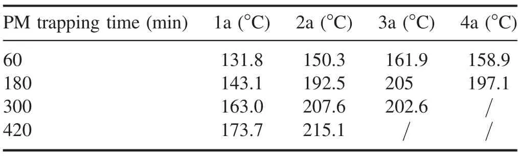
Table 2.Peak temperatures of the DPF internal measuring points.

Table 3.Time of peak temperatures of the DPF internal measuring points.
Tables 2 and 3 respectively list the peak temperature and time of peak temperature of each measuring point in the DPF.It can be concluded that as the PM trapping amount increased,the peak temperature of the same measurement point inside the DPF showed an increasing trend and the time of the peak temperature exhibited a delay. The maximum values of the peak temperatures of the DPF60and DPF180occurred at measure point 3a and were 161.9°C and 205.0°C, respectively.Since the temperature measurement points of 1a and 4a were close to the inlet and outlet respectively of the NTP active material injection,the internal temperature of both ends of the DPF was lower than that of the middle section of the DPF. No temperature drop occurred at measuring point 4a in the DPF300but it was determined that the highest temperature of the DPF300regeneration was 207.6°C and occurred at measuring point 2a.A temperature decrease was not observed at the measuring points 3a and 4a in the DPF420but the highest temperature of the DPF420regeneration was 215.1°C which was higher than the highest temperature of the DPF300.It was observed that, with the increase in the amount of trapped PM, the internal maximum temperature of the DPF regeneration tended to increase.On the other hand,the results also indicate that the larger the amount of trapped PM, the more intense the internal reaction was,and the more heat was released. As shown in figure 5, the mass of the PM decomposed by NTP oxidation increased with the increase in the amount of trapped PM. Therefore, under the same regeneration conditions of the NTP injection system,a higher amount of trapped PM is conducive to promote the reaction between the NTP active substances and the PM.
3.3. DPF internal temperature gradient
During the regeneration process of the DPF, a large internal temperature difference will lead to different degrees of thermal expansion in certain areas and the thermal stress caused by the uneven thermal expansion will also lead to the fracture of the DPF carrier [38]. The average temperature gradient between two adjacent measuring points is represented by TG,which is calculated as follows:
where Taand Tbrepresent the temperatures of the measuring point a and the measuring point b at a certain time respectively; Labrepresents the distance between the measuring point a and the measuring point b.
The analysis of the internal temperature of the DPF regeneration and PM decomposition mass indicates that the internal oxidation decomposition reaction of the DPF420was the most violent. Figures 8 and 9 show the axial and radial temperature gradients respectively of the DPF420as a function of time. The maximum axial temperature gradient of the DPF420with the valve of 4.28°C cm−1occurred between measuring points 1a and 2a and the maximum radial temperature gradient with the valve of 1.78°C cm−1occurred between the measuring points 2b and 2c. The DPF is not damaged by thermal stress when the temperature gradient is less than 35°C cm−1[25]. The maximum internal temperature and temperature gradient of the DPF regeneration test were much lower than the failure limit.The NTP regeneration technology assisted by the exhaust waste heat endows the DPF with excellent thermal durability and increases the service life of the DPF.
4. Conclusion
A regeneration test of DPFs loaded with different amounts of PM was carried out using an NTP injection system assisted by exhaust waste heat. The regeneration performance and thermal safety of the NTP technology were investigated by monitoring the decomposition products(COx)of the PM and the internal temperature of the DPF. The conclusions are as follows:
(1) The concentration of the PM decomposition products CO and CO2increased and the removal quality of the PM inside the DPF increased as the amount of trapped PM increased.The decomposition product CO2was the key factor to determine the removal amount of PM.
(2) The concentration of the remaining O3after DPF regeneration decreased as the amount of trapped PM increased. The oxidative decomposition reaction of the PM deposited in the DPF and the NTP active substances was promoted by a higher amount of trapped PM and the utilization ratio of the NTP active substances was improved.
(3) The peak temperature at the same measuring point inside the DPF generally increased and the phases of the peak temperature were delayed as the amount of trapped PM increased.
(4) Both the peak temperature and temperature gradient during regeneration were lower than the DPF failure limit. The NTP regeneration assisted by exhaust waste heat exhibited good thermal durability,which increases the service life of the DPF.
Acknowledgments
This work is currently supported by National Natural Science Foundation of China (Nos. 51806085, 51676089), China Postdoctoral Science Foundation (No. 2018M642175),Jiangsu Planned Projects for Postdoctoral Research Fund(No.2018K101C) and Jiangsu University Youth Talent Cultivation Program Funded Project.
 Plasma Science and Technology2020年1期
- Plasma Science and Technology的其它文章
- Diffusion of ions in an electrostatic stochastic field and a space-dependent unperturbed magnetic field
- Influence of heating on the discharge characteristics of a hollow cathode
- Design and characteristics of a new type laminar plasma torch for materials processing
- Effects of inter-electrode insertion on the performance and thermal flow fields of a hollow-electrode plasma torch
- Kinetic simulation of the transition from a pulse-modulation microwave discharge to a continuous plasma
- Numerical simulation of atmospheric pulsemodulated radio-frequency glow discharge ignition characteristics assisted by a pulsed discharge