
Investigation on plasma characteristics in a laser ablation pulsed plasma thruster by optical emission spectroscopy
2020-05-06 05:59YuZHANG张宇JianjunWU吴建军YangOU欧阳DaixianZHANG张代贤andJianLI李健
Plasma Science and Technology 2020年4期
Yu ZHANG (张宇),Jianjun WU (吴建军),3,Yang OU (欧阳),Daixian ZHANG (张代贤) and Jian LI (李健)
1 College of Aerospace Science and Engineering,National University of Defense Technology,Changsha 410073,People’s Republic of China
2 China Aerodynamics Research and Development Center,Mianyang 621000,People’s Republic of China
Abstract
Keywords: laser ablation pulsed plasma thruster,optical emission spectroscopy,plasma,propulsion performance
1.Introduction
Because of the advantages of small,compact,low-mass,and high specific impulse,pulsed plasma thrusters (PPTs) are expected to be used for small satellites [1–5].However,the propulsion performances(e.g.specific impulse and efficiency)of PPT severely restrict its further application [6,7].
Early in the year 2000,Horisawa et al proposed a laserassisted plasma thruster which combined the laser ablation and electromagnetic acceleration [8].Meanwhile,various experimental means were used to study the plasma characteristics between the electrodes of thruster [9–12].The experimental results showed that although the propulsion performances of the thruster were improved,the phenomenon of ‘late ablation’ still reduced the efficiency.In order to overcome the shortage of ‘late ablation’ and further improve the efficiency,a novel laser ablation plasma thruster (LAPPT) has been proposed in our previous work [7],which is considered as a representative example of exploring a novel type of space micropropulsion[13].As shown in figure 1,the LA-PPT consists of a solid propellant,a ceramic tube,an insulator,and a pair of rectangular electrodes[7].At first,the solid propellant placed inside the ceramic tube is irradiated by a laser beam,decomposed into plasma,gas or solid particles,and injected into the area between electrodes.Then the effluent induces discharge arcs across the pair of electrodes,as the discharge current increases,the plasma is enhanced,the gas is ionized,the solid particles are broken into smaller pieces by particle collision processes and chemical reactions.Finally,all particles are accelerated by electromagnetic and aerodynamic forces.Because of the separation of propellant ablation and discharge,the LA-PPT can effectively overcome the shortage of ‘late ablation’ which significantly constraints the performance of traditional PPT [6].Therefore,the LAPPT can obtain higher propulsion performance,such as specific impulse and efficiency.

Figure 1.Schematic of the LA-PPT.Reprinted from [7],Copyright(2016),with permission from Elsevier.
As a novel plasma thruster,the working process of LAPPT is very complex,involving a variety of physical fields(e.g.,optical,electric,magnetic and thermal).Meanwhile,the LA-PPT operates in pulse mode,and the duration of the single pulse is very short (about 10 μs).The plasma characteristics in the thruster can directly reflect the working state of the thruster,and help to understand the internal mechanism of LA-PPT.Many investigations have been carried out to deal with the basic concepts of detecting the characteristic of plasma [14].Among the detecting techniques,due to the advantages of high accuracy and no intrusiveness,optical emission spectroscopy (OES) is usually used to record the emission intensity of each wavelength.Hence,in this paper,the OES is adopted to investigate the plasma characteristics between the electrodes of LA-PPT.
2.Experiment
The LA-PPT used in this paper is shown in figure 1.A rectangular electrode configuration with four capacitors (capacitance: 3 μF per capacitor,peak charged voltage: 2000 V)and a ceramic nozzle (material: BN,inside diameter: 6 mm,length: 30 mm) is used.The electrodes are made of two parallel plates of non-oxide copper with an inter-electrode space of 40 mm,length of 30 mm,width of 15 mm,and thickness of 3 mm.The ceramic tube is placed in the central position between the electrodes.The propellant is placed inside the ceramic tube.Because of the unique structure of this thruster,metals can also be adopted as the propellant,and higher specific impulse,thrust efficiency will be obtained.In our experiments,the metal aluminum is adopted as the solid propellant,and four uniformly distributed positions along the centerline of the thruster are chosen to be measured by OES.If the outlet of the ceramic tube is taken as the origin of the coordinates,the coordinates of the four positions are characterized as position 0(0,0),position 1(10 mm,0),position 2(20 mm,0) and position 3 (30 mm,0),as shown in figure 1.Figure 2 shows the OES experimental set-up.This timedependent measurement system consists of the following instruments:(1)the optical fiber(QP600-2-SR),which is used to transmit the optical signals emitted by the discharge in the vacuum tank to the spectrometer in the cleanroom; (2) the spectrometer (Acton SP2300i),which is used to disperse and diffract optical signals; (3) the ICCD camera (PI-MAX2),which is used to collect and enhance the optical signals transmitted from the spectrometer; (4) the controller (ST-133),which is used to control the rotation of the grating and the shutting time of the camera; (5) the functional signal generator,which can control the time sequence of the laser;(6) the Nd:YAG laser (SightLight 600),with the wavelength of 1064 nm,the single pulse energy of 600 mJ and the full width at half maximum of 7 ns.Otherwise,to eliminate the interference of the ambient gases on the OES measurement,the pressure of the vacuum tank is below 3.0 × 10⁻³Pa.
In order to ensure the stable output of the laser and the effective working of the spectrometer,the time sequences of the OES measurement system should be reasonably set,as shown in figure 3.The software named Winspec v2.6 is adopted to control the spectrometer.As the spectrometer works in a gate operation mode,the shutter of the ICCD Camera will open after a trigger signal from the software Winspec v2.6.The software Winspec v2.6 is set to internal trigger mode and the trigger frequency is 1 Hz,hence the controller will start to work after the internal trigger signal.Meanwhile,the controller sends out a trigger signal T0.When the functional signal generator receives the trigger signal T0,it outputs two-way trigger signals: the Flashlamp trigger and the PC trigger.In order to keep consistent with the flash frequency of the laser,the frequency of the Flashlamp trigger is set to 20 Hz,and the pulse width greater than 200 μs.Otherwise,to ensure the pumping time and output stable laser,the PC trigger should be set delay time (τtrigger) of 215 μs over the Flashlamp trigger,and the pulse width of the PC trigger should be greater than 100 μs.However,when the laser pulse is generated,the plasmas do not be produced immediately.About 13.3 ns will be taken for the laser to propagate in a 4 m long optical fiber,about 400 ns will be taken for laser ablation to produce plasmas,about 2.5 μs will be taken for the plasmas to pass through the ceramic tube.Finally,the gate delay time of the ICCD camera can be set as
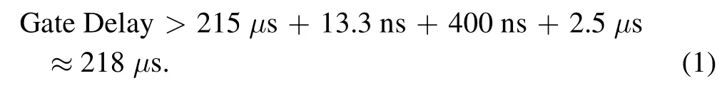
The gate width of the ICCD camera is set as Gate Width = 200 ns–1 μs.
3.Results and discussion
3.1.Variation characteristics of plasma
Spectrograms at position 1 under the discharge voltage of 2000 V with different delay times (218 μs,220 μs,222 μs)are presented in figure 4.Because of the periodicity (about 4 μs)of discharge voltage and current,the spectrograms at the same position in the discharge channel of thruster also have periodicity.At the delay time of 218 μs,the spectral lines with higher intensity are mainly distributed in the wavelength range of 400–500 nm.
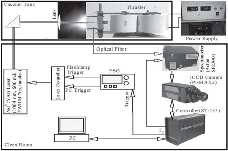
Figure 2.Schematic of the experimental set-up.

Figure 3.Time sequence of the measurement system.
When a particle transits from the excited state j to the excited state i through spontaneous emission,the emission intensity emitted by the process can be defined as

where Ijirepresents the emission intensity,V is the equivalent area of plasma luminescence region,Ajiis the spontaneous emission coefficient,h is Planck’s constant,c is the speed of light,η is the correction coefficient,λjiis the spontaneous emission wavelength,Njrepresents the particle concentration in the excited state j.
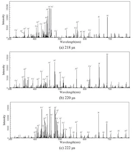
Figure 4.Spectrograms in discharge channel of thruster at different times.
We can conclude from equation (2),for the same spectrogram,the values of these parameters (V,Aji,h,c,η,λji) are the same,hence the emission intensity Ijiis proportional to the particle concentration in the excited state Nj.It can be seen in figure 4(a),at the delay time of 218 μs,the concentration of Al+is the highest,followed by Al2+.This means that most of the particles in the discharge channel of thruster are ionized at this time.The particle Al is produced by laser ablating propellant,the particle Cu is produced by particles colliding with the electrodes of thruster.Otherwise,there are also particles of Al3+and Cu+in the discharge channel,which indicates that the ionization degree in the area is rather high.The existence of H and O+spectral lines indicates that there is a small amount of water or air in the vacuum tank.As shown in figure 4(b),at the delay time of 220 μs,due to the periodicity of thruster discharge,the discharge intensity is low at this time,and the particle Al is produced by laser ablation constantly,hence the concentration of Al is significantly increased at this time.Because the discharge intensity is low and the ionization of particles is weak,large quantities of Al+that existed at the delay time of 218 μs continue to exist at this time.In addition,the increase of spectral lines and concentration of Cu element indicates that the collision between particles and electrodes is enhanced at this time.As shown in figure 4(c),at the delay time of 222 μs,the discharge intensity is enhanced,more particles are ionized,hence both the spectral lines and the emission intensity are increased.Large quantities of Al existed at the delay time of 220 μs are ionized into Al+.The increase of the concentration of Cu+and Cu indicates that the collision between particles and electrodes continues to be enhanced at this time.The increase of the concentration of Al3+indicates that the ionization is enhanced.
It can be concluded from figure 4,the ionization of the particle depended on the discharge intensity in the discharge channel.With the discharge proceeding,the collision between particles and thruster electrodes becomes more and more serious.However,the spectral lines of H and O+do not vary with the delay time.This is because the H and O elements exist in the ambient gas and are not affected by the state change of the thruster.
3.2.Effect of discharge energy on the plasma characteristics
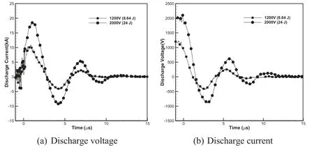
Figure 5.Discharge characteristics with different discharge energies.

Figure 6.Spectrograms with different discharge energies.
The discharge voltages and currents with different discharge energies are experimentally measured,which is essential to investigate the effect of discharge energy on the plasma characteristics.The discharge current is monitored with a current monitor (PEARSON Current Sensor 4997),and the discharge voltage is measured using a standard high-voltage probe(Tektronix P5100).Figure 5 shows the discharge characteristics of LA-PPT with different discharge energies.With different discharge energies,the amplitudes of discharge voltage and current vary,but the law of waveforms changing is the same.The higher the charged energy,the higher the discharge current being achieved,which means more energy deposited in the discharge arc as the charged energy increasing.In addition,about 1 μs after the start of discharge,the discharge current raises to the maximum.This indicates that the working response of LA-PPT is very fast.

Figure 7.Spectral lines of H at different positions with different delay times.
Spectrograms at position 1 with 218 μs delay time under the discharge voltage of 1200 V(8.64 J)and 2000 V(24 J)are presented in figure 6.As shown in the figure,with lower discharge energy,both the spectral lines and emission intensity are relatively weak.It indicates that the discharge energy of the thruster directly determines its ionization ability.With higher discharge energy,the higher ionization degree of the propellant can be obtained.However,comparing the spectrograms of the Cu element in figures 6(a)and(b),with higher discharge energy,the concentration of Cu element is increased slightly.Hence,it can be concluded that discharge energy has little effect on the collision between particles and electrodes.That is,the life of thruster is not reduced by increasing discharge energy.
3.3.Velocity characteristics of plasma in the discharge channel of thruster
According to the working process of the LA-PPT,the motion of plasma particles in the thruster can be divided into two stages:laser-induced acceleration through the ceramic tube and discharge acceleration through the discharge channel.The velocities of plasmas at different positions along the discharge channel are different,which means that the time when the plasmas reach the position is different.Hence,we can calculate the velocities of plasmas in the discharge channel by measuring the time of plasmas reaching different positions along the discharge channel.The average velocity of laser ablation products in the ceramic tube can be obtained by the time difference between laser irradiation and plasmas reaching position 0 (Δt0)

Assuming that the time difference between plasmas reaching position 0 and position 1 is Δt0–1,the time difference between position 1 and position 2 is Δt1–2,the time difference between position 2 and position 3 is Δt2–3,the average velocity between the four measuring positions can be calculated as

In the experiment,the time of plasma reaching the position is obtained by setting different delay times.Because the spectral line of H (about 656 nm) is slightly affected by the thruster conditions,the wavelength range of 645–675 nm is selected to observe the time of plasma reaching the position.
Figure 7 shows the spectral lines of H at different positions with different delay times under the discharge voltage of 2000 V (24 J).It can be obtained from figure 6 that the plasmas reach the position 0 at the delay time of 3.019 μs,reach the position 1 at the delay time of 3.500 μs,reach the position 2 at the delay time of 3.700 μs,reach the position 3 at the delay time of 3.850 μs.Combining equations (3) and (4),the average velocities of plasmas between different positions can be calculated as v0= 3.3 km s-1,v0–1= 20.8 km s-1,v1–2= 50.0 km s-1,v2–3= 66.7 km s-1.According to the working process of LA-PPT,the velocity of plasmas produced by laser ablation is 3.3 km s-1,then the velocity of plasmas reaches 66.7 km s-1at the outlet of thruster through electromagnetic acceleration.
Meanwhile,the specific impulse can be obtained

where g is the gravitational acceleration (9.8 m s-2).
However,the velocity in equation(5)only represents the velocity of ions,rather than the velocity of all ablated propellant.Therefore,the impulse bit of LA-PPT is experimentally measured utilizing thrust stand which is detailed introduced in the literature [7].The impulse bit is 516 μNs,which is contributed by the entire ablated propellant including ions,neutral gas and solid particles.Hence the specific impulse is defined as follows:
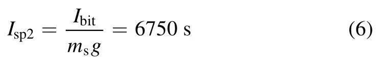
where msis the mass ablated per shot,and equals to 7.8 μg.
The specific impulse Isp1calculated by the velocity of plasmas is higher than the specific impulse Isp2obtained through impulse bit,which means that the ablated propellant is not fully ionized.However,the value of Isp1is closed to Isp2,this indicates that the ionization degree in the ablated propellant is quite high.
The velocity of neutral gas and solid particles is rather small compared with the ions,and the impulse bit is mainly contributed by the ions.Hence the mass of ions can be obtained as
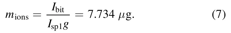
Hence the ionization degree can be calculated as
The thrust efficiency of the thruster can be calculated as
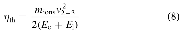
where Ecis the discharge energy of the thruster,Elis the laser energy per shot.
In this experiment,Ecis equal to 24 J,and Elis equal to 0.6 J,hence the thrust efficiency of the thruster can be calculated by equation (8),which equals to 70%.It can be concluded that both the specific impulse and thrust efficiency of LA-PPT are significantly improved comparing with traditional PPT.
4.Conclusions
In this paper,we use the optical emission spectroscopy to investigate the plasma characteristics in LA-PPT.Then the variation characteristics of plasma,the effect of the discharge energy and velocity characteristics of plasma are experimentally studied.According to the experimental results,the main conclusions are obtained.
(1)The ionization of particles depended on the discharge intensity in the discharge channel.The intensity of spectral lines varies periodically with the discharge process.With higher discharge energy,the higher ionization degree of the propellant can be obtained.But the discharge energy has little effect on the collision between particles and electrodes.
(2) The plasmas can obtain initial velocity of several kilometers per second produced by laser ablation,and then the velocity of plasmas will reach tens of kilometers per second through electromagnetic acceleration in the discharge channel of the thruster.
(3) With total energy of 24.6 J,the ionization degree of ablated propellant can reach 99.15%,the specific impulse and thrust efficiency are 6750 s and 70%,which are excellent propulsion performance for space micro propulsion.
Acknowledgments
The authors would like to thank National Natural Science Foundation of China for the financial assistance provided under the grant number 11772354 for this work.
猜你喜欢
环球时报(2022-08-02)2022-08-02
Plasma Science and Technology(2022年7期)2022-08-01
Plasma Science and Technology(2021年2期)2021-02-27
Plasma Science and Technology(2020年9期)2020-09-14
江苏教育·书法教育(2020年10期)2020-09-10
当代人(2020年4期)2020-05-08
海峡姐妹(2018年10期)2018-12-26
美与时代·美术学刊(2018年7期)2018-11-10
戏剧之家(2018年12期)2018-06-13
人民中国(日文版)(2015年10期)2015-04-16
 Plasma Science and Technology2020年4期
- Plasma Science and Technology的其它文章
- Study on influencing factors of ion current density measurement in corona discharge of HVDC transmission lines
- Trap distribution of polymeric materials and its effect on surface flashover in vacuum
- Improvement of the electrical resistivity of epoxy resin at elevated temperature by adding a positive temperature coefficient BaTiO3-based compound
- Controlling fine particles in flue gas from lead-zinc smelting by plasma technology
- Kinetic simulation of an electronegative plasma with a cut-off distribution and modified Bohm criterion
- Suppression of a spontaneous dust density wave by modulation of ion streaming