Growth model of cavity generated by the projectile impacting liquidfilled tank
2020-06-28 03:02BeileiZhoJigungZhoCunynCuiYongshengDunYnWng
Defence Technology 2020年3期
Bei-lei Zho , Ji-gung Zho , Cun-yn Cui ,*, Yong-sheng Dun , Yn Wng
a Department of Aerospace Science and Technology, Space Engineering University, Beijing 101416, China
b Department of Electronic and Optical Engineering, Space Engineering University, Beijing 101416, China
Keywords:Projectile Impact Liquid-filled tank Cavity Axial growth model Radial growth model
ABSTRACT The high-speed impact of a projectile on a liquid-filled tank causes the hydraulic ram,in which a cavity is formed. To study the growth characteristics of the cavity, the formation mechanism of the cavity is analyzed. The effect of Reynolds number and Mach number on drag coefficient is considered, the axial and radial growth models of the cavity are established respectively. The relative errors between the cavity length calculated by the axial growth model, the cavity diameter calculated by the radial growth model and Ma L. Y. test results are less than 20%, which verifies the effectiveness of the axial and radial growth models. Finally, numerical simulation is carried out to study the growth characteristics of the cavity caused by the projectile impacting the satellite tank at the velocity of 4000 m/s. The cavity length and diameter calculated by the axial and radial growth models agree well with those obtained by simulation results, indicating that the cavity length and diameter in satellite tank can be accurately calculated by the axial and radial growth models.
1. Introduction
The impact of a projectile on the liquid-filled tank results in a hydrodynamic ram, which includes the shock stage, drag stage,cavity stage and exit stage [1]. During the shock stage, the hemispherical shock wave is generated and the pressure loading is exerted on the walls. As the projectile propagates forward, its velocity attenuates due to the viscous drag. Part of projectile kinetic energy is converted into liquid kinetic energy,a cavity forms behind the projectile.The exit stage occurs when the projectile penetrates the back wall of the tank. Among the four stages, the cavity stage plays a key role.On the one hand,the growth process of the cavity is affected by the shock wave. On the other hand, the cavity expansion squeezes the liquid and imposes the pressure loading on the walls. Therefore, it is necessary to further study the growth characteristics of the cavity.
Studies on cavity are originated from the naval weapons,which aim at analyzing the cavity caused by the water entry of high speed torpedoes,missiles and projectiles. Worthington A.M.(1900),who was considered as the first person to study water entry, recorded the phenomenon of spherical projectiles impacting different liquids by means of instantaneous photography [2]. Lundstrom E. A. and Fung W. K. (1976) performed a series of tests where the armour piercing projectiles with the diameter of 12.7 mm and 14.5 mm entered the water at the velocity of 800 m/s~1070 m/s [3]. They analyzed the formation, closure and collapse of the cavity, and proposed an empirical formula for predicting the cavity radius.Lee M. et al. (1997) deduced formulations of cavity radius and cavity wall velocity for the spherical projectile entering water vertically[4]. Ma Q.P. (2014) carried out numerical simulation in which cylinders with different head cones entered the water at a velocity of 500 m/s [5]. He concluded that the head cone angle and drag coefficient were the main factors affecting the cavity radius. Unlike the cavity induced by water entry,the cavity in hydrodynamic ram is formed in a closed container, its growth is constrained by the container walls. Therefore, the conclusions in water entry cannot accurately describe the cavity characteristics in hydrodynamic ram.
Crater caused by the penetration of shaped charge jet has also become the focus of many studies.Szendrei T.(1983)first proposed a radial growth equation for crater[6],and Held M.(1995)made a slight modification [7], which constituted the classical Szendrei-Held equation. Held M. (1996) also conducted a test in which the shaped charge jet with a diameter of 42 mm was fired at the velocity of 7.9 km/s against a plexiglass container filled with water[8].The radial expansion of the crater was recorded as a function of time,and the experimental results agreed well with the calculation results of Szendrei-Held equation.Unlike the projectile with initial kinetic energy, the shaped charge jet has sustained energy input and stronger penetration capability. Thus, there are some differences between the cavity characteristics in hydrodynamic ram and crater characteristics in jet penetration.
Since the 1970s, a large number of tests and numerical simulations on hydrodynamic ram have been carried out. Nishida M.et al.(2006)conducted a test in which the spherical projectile was accelerated to 40~200 m/s to impact a water-filled vessel [9].Disimile P. J. et al. (2008) performed tests in which the 12.7-mmdiameter projectiles made of tungsten, steel and aluminum were shot into a water-filled tank at the velocity of 341 m/s,389 m/s and 455 m/s [10]. Varas D. et al. (2012) used the ALE simulation approach to reproduce a projectile impacting the 60%, 75%, 100%water-filled tank at the velocity of 600 m/s and 900 m/s [11,12].These study mainly focus on the deformation of the tank wall, the peak pressure of shock wave and the attenuation of projectile velocity. Lecysyn N. et al. (2010) analyzed the cavity growth theoretically and deduced the formula of cavity radius as a function of time [13]. However, the effect of the shock wave on the cavity growth is neglected,and the axial growth law of cavity has not been explored.
In this paper, the formation mechanism of the cavity after a projectile impacting the liquid-filled tank is analyzed.The effect of the shock wave on the axial growth of cavity and liquid motion on the radial growth of the cavity are considered, and the axial and radial growth models of the cavity are established respectively.The validity of the axial and radial growth models were verified based on Ma L. Y. test results. Finally, with the method of numerical simulation and cavity growth models,the growth characteristics of the cavity caused by the projectile impacting the satellite tank at the velocity of 3000 m/s are analyzed.
2. The formation mechanism of cavity
When a high-speed projectile enters a liquid-filled tank, a boundary layer forms around the projectile.As the fluid flows back along the boundary layer,the kinetic energy in the boundary layer is dissipated by the liquid viscosity, and the velocity of the fluid decreases. Due to the continuity of the flow, the boundary layer becomes thicker, and more low-speed fluids flow through at the same time, which results in the adverse pressure gradient. Under the action of the adverse pressure gradient, the flow slows down further.Finally the kinetic energy of the fluid in the boundary layer is insufficient to maintain the downstream flow. Thus, boundary layer separation occurs.
Then,double-line vortices with opposite rotation direction and regular arrangement appear on both sides of the projectile tail.These vortices, called Karman Vortex Street, fall off periodically.Part of the projectile kinetic energy is transformed into the liquid kinetic energy, the liquid is accelerated and the Reynolds number enlarges. If the Reynolds number is large enough,the randomness of vortices shedding rises,finally Karman vortex street turns into a turbulent wake[14].Meanwhile,the external air enters through the perforation at the impact point, the turbulent wake and liquid behind the projectile are squeezed.The liquid flows perpendicular to the impact direction and the cavity is formed.
Fig.1. Schematic diagram of a cavity caused by a spherical projectile impacting liquidfilled tank.
Fig. 1 presents the schematic diagram of a cavity caused by a spherical projectile impacting liquid-filled tank. The projectile is shot vertically into the tank along the x-axis,the length and height of the tank are d and 2h, respectively. It is assumed that the moment when the projectile begins to impact the liquid is t=0.The distance from the impact point to the cavity head is the cavity length in the axial direction,which is expressed as l.The maximum radius at the cavity bottom is the cavity radius in the radial direction, which is expressed as r.
3. Cavity growth model
3.1. Axial growth model of cavity
In the studies of hydrodynamic ram[15],the length of cavity is assumed to be equal to the projectile axial displacement, which means the axial growth velocity of cavity uais the same as the projectile velocity up.

When the projectile moves in the liquid hydrazine, it is only subjected to drag force. From Newton’s second law, the following can be deduced [16]:

where, ρlis the density of the liquid; ρpis the density of the projectile;Vpis the projectile volume;Apis the cross section area of the projectile;CDis the drag coefficient.For spherical projectile,Vp=4/Ap=.

Fig. 2. The curve of drag coefficient CD changing with Reynolds number Re [14].
Two parameters on which the drag coefficient can be very dependent are the Reynolds number (Re) and the Mach number(Ma).The accurate dependence of the drag coefficient on Re and Ma is generally quite complex.Reasonable simplifications are made in Ref.[14].For Ma<0.5,the drag coefficient is essentially independent of Ma, it is strongly dependent on Re, as is indicated in Fig. 2 [14].When the projectile impacts the liquid-filled tank, the turbulent wake is generated at the tail of the projectile, and the Reynolds number Re>103. Within this range, the drag coefficient basically remains unchanged. For spherical projectile, CD=0.4.
For Ma ≥0.5,the drag coefficient is a strong function of Ma,and the influence of Re is secondary. The relationship between drag coefficient and Mach number is shown in Fig. 2 [14]. For spherical projectile, with the increase of Mach number, the drag coefficient first increases rapidly and then decreases slowly. For 0.5 ≤Ma≤3,the function between drag coefficient and Mach number is fitted,as shown in Fig. 3(a).

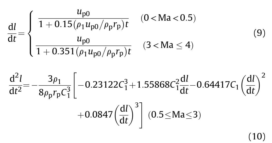
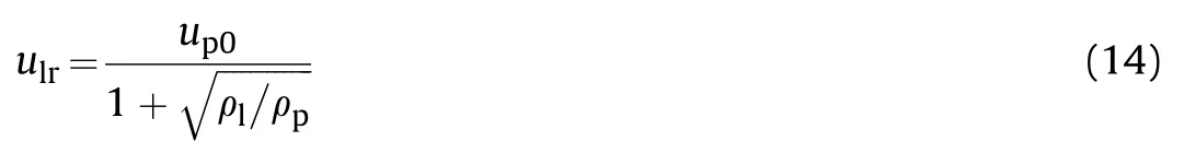
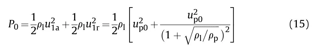
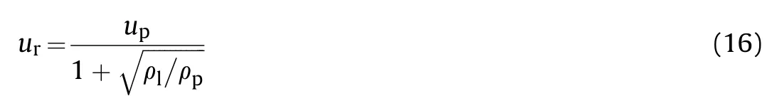
For spherical projectile, the drag coefficient remains approximately constant when 3 Mach number is defined as Ma =Clis the sound velocity of the liquid. For 0 where, up0is the initial velocity of the projectile. Eq. (3) can also be expressed as: Substituting Eq. (6) into Eq. (2), the following can be gained: If the length of the cavity is l,the projectile velocity upis defined as: Then, the length of the cavity can be solved as follows: Fig. 3. (a) Fitting curve of drag coefficient for 0.5 ≤Ma≤3; (b) Curves of drag coefficient varying with Mach number for different shapes. The differential Eq. (9) and Eq. (10) constitute the axial growth model of the cavity,in which the initial condition is t=0,l=0,and the boundary condition is 0 ≤l ≤d. In the analysis of the radial growth of the cavity, the static pressure is neglected and the dynamic pressure produced by the liquid motion is considered.The pressure P at the cavity bottom can be expressed as: where,ulis the liquid velocity at the cavity bottom. As the pressure changes with the increase of the cavity radius,Szendrei T. [6] supposed that the product of cavity pressure and cross section area at the cavity bottom always remain constant. where, P0is the initial stagnation pressure; Apis the area of projectile at the cavity bottom;Pris the dynamic pressure at the cavity bottom;Aris the cross section area at the cavity bottom. In the process of the projectile getting into the liquid,The liquid in contact with the projectile produces both axial and radial motion.The axial velocity of liquid ulais equal to the initial velocity of projectile up0: The radial velocity of liquid ulris proportional to the initial velocity of projectile up0[13]: The initial stagnation pressure P0is as follows: The projectile continues to move forward, generating a cavity behind it.The liquid at the bottom of the cavity moves radially.The radial velocity at the bottom uris proportional to the velocity of projectile upat a certain time. The dynamic pressure Prat the cavity bottom can be expressed as: The cavity radius at the bottom is r. Substituting Eqs. (15) and(17) into Eq. (12), the following can be obtained for spherical projectile: As the cavity radius is related to the velocity of the projectile at a certain time, equation (5), equation (7) and equation (18) constitutes the radial growth model of the cavity, in which the initial condition is t=0, r=rp, and the boundary condition is 0 ≤r ≤h. Ma L. Y. et al. (2010) performed a test where a steel projectile with the diameter of 9.5 mm was shot into an aluminum vessel filled with water at the velocity of 686 m/s [15]. The length and diameter of the cavity at 441 μs,774 μs and 1107 μs was recorded by a high-speed camera,as illustrated in Fig.4. The vessel is a cuboid with 50, 40, 40 and 0.4 cm in length, width, height and wall thickness, correspondingly. Based on Ma L. Y. test conditions, the axial and radial growth models are used to calculate the length and diameter of the cavity at 441 μs, 774 μs and 1107 μs, 1440 μs, 1773 μs and 2106 μs. The related parameters of water[17],vessel and projectile are shown in Table 1. The impact velocity of projectile is 686 m/s and the Mach number in water is less than 0.5,so Eq. (9)is used to calculate the cavity length. The cavity length ltin the test, the cavity length lccalculated by axial growth model,the cavity diameter Dtin test,the cavity diameter Dc(Dc=2r)calculated by radial growth model and the relative errors ε are shown in Table 2. It is concluded that the calculated cavity length is larger than the cavity length in the test.With the increase of time,the calculated cavity length is close to the test results,and the relative errors between them decreases.When t<1440 μs, the calculated cavity diameter is smaller than the test results. When t>1773 μs, the calculated cavity diameter is larger than the test results. The reason for the error is that a series of simplifications have been made in the derivation of the axial and radial growth models. The influence of shock wave are neglected.Overall, the relative errors between test results and calculation results are less than 20%, which verifies the effectiveness of the axial and radial growth models. The satellite may be impacted by a high speed projectile in the launch process. The satellite tank filled with liquid hydrazine,which accounts for a large part of the satellite mass, is one of the most vulnerable components[18].The hypervelocity impact of the projectile on a satellite tank generates a cavity in liquid hydrazine.Compared with the impact test, numerical simulation has the advantages of low cost and good repeatability to study the cavity characteristics. Numerical simulation is carried out to study the axial and radial growth characteristics of the cavity in the satellite tank. Fig. 4. The length and diameter of cavity recorded by a high-speed camera at t=441 μs, 774 μs,1107 μs,1440 μs,1773 μs and 2106 μs. Table 1 Parameters of water,vessel and projectile. Table 2 Test and calculation results of axial and radial growth models. Fig.5. Finite element model of the projectile impacting satellite tank;the right side is the model cut in half. The satellite tank consists of a straight cylindrical section, a upper hemisphere and a lower hemisphere.It is 50 cm in diameter,120 cm in height and 2 mm in wall thickness. The tank is made of titanium and is filled with liquid hydrazine. ANSYS/LS-DYNA software is used to simulate the situation in which a spherical steel projectile with a diameter of 4 cm impacts the satellite tank at the velocity of 4000 m/s. The finite element model of a projectile impacting the satellite tank is displayed in Fig. 5. The simulation model consists of the projectile, satellite tank,liquid hydrazine and air.The interaction between the projectile and satellite tank is achieved through the eroding surface-to-surface contact. Lagrange grids are constructed for the projectile and tank, yet Euler grids are constructed for liquid hydrazine and air.These two grids are coupled through Arbitrary Lagrangian-Eulerian (ALE) algorithm [19]. The air domain is a cylinder with the diameter of 80 cm and the height of 150 cm.The projectile and satellite tank are located in the air domain.To ensure the air flows into satellite tank and forms a cavity, air and liquid hydrazine meshes share the same nodes at their interfaces. The mesh sizes of the projectile,satellite tank,liquid hydrazine and air are 0.4 cm,1 cm,1 cm and 2 cm, respectively. The computing time step is 0.6 μs.The steel projectile is modelled using the constitutive equation MAT_JOHNSON_COOK and the state equation EOS_-GRUNEISEN. The titanium tank is modelled using the material model MAT_PLASTIC_KINEMATIC. Since the density, boiling point and critical temperature of liquid hydrazine are close to the values of water(within 2%)[20],the constitutive equation MAT_NULL and the state equation EOS_GRUNEISEN of water are used to describe liquid hydrazine. Air is modelled using the constitutive equation MAT_NULL and the state equation EOS_LINEAR_POLYNOMIAL.Thematerial parameters and state equation parameters used are listed in Table 3 [21,22]. Where, S1is the slope coefficient of the us-upcurve; C4and C5are the polynomial equation coefficients, A is the quasi-static yield stress,B is the strain hardening modulus,E is the elastic modulus, σsis the yield strength, and σbis the tensile strength. Table 3 Material parameters and state equation parameters. Fig. 6. Theoretical curve and simulation results of projectile velocity. The impact velocity of projectile is 4000 m/s and the Mach number is Ma=2.67, so Eq. (7) is used to calculate the projectile velocity theoretically. Moreover, the projectile velocities at different times are obtained according to the simulation results.The theoretical curve and simulation results are plotted in Fig. 6.t=0 indicates the moment when the projectile begins to impact liquid hydrazine.When t<100 μs,the projectile velocities obtained by simulation are larger than the calculated velocities. t>125 μs,the projectile velocities obtained by simulation are smaller than the calculated velocities. The velocity of projectile decreases rapidly due to the viscous resistance. In numerical simulation, the kinetic energy lost by the projectile is converted into the kinetic energy of liquid hydrazine and the deformation energy of the tank walls.The attenuation trend of projectile velocities obtained by simulation is consistent with the theoretical curve.The solution to equation(10)is t=234 μs, l=0.5 m, which demonstrates that the projectile passes through the satellite tank at t=234 μs.The residual velocity of projectile is 1345.6 m/s. The simulation results indicate that the residual velocity of projectile is 1284.3 m/s at t=234 μs. The relative error between them is 4.6%,which verifies the effectiveness of the simulation model. Fig.7 presents the evolution of cavity shape when the spherical projectile penetrates the satellite tank. With the expansion of the cavity, the axial growth velocity is higher than the radial growth velocity, which results in a slender cavity. The cavity length obtained by simulation is 46.9 cm at t=234 μs, and the cavity radius obtained by simulation is 9.05 cm at t=234 μs. The length and diameter of the cavity at different times are obtained by simulation results. Meanwhile, the axial and radial growth models are used to calculate the length and diameter of the cavity. The growth curves of the cavity length and diameter are plotted, the growth model results are compared with the simulation results and the relative errors between them are calculated,as shown in Figs. 8 and 9. Fig. 7. The cavity shape at different times after the projectile enters the satellite tank. Fig. 8. (a) Growth curve of cavity length and simulation results; (b) the relative errors between growth curve and simulation results. Fig. 9. (a) Growth curve of cavity diameter and simulation results; (b) the relative errors between growth curve and simulation results. As shown in Figs. 8 and 9, the growth trend of the simulation results agrees well with the growth curve.Due to the penetration of the projectile,the growth velocity of the cavity in the axial direction is obviously greater than that in the radial direction. The growth velocity of the cavity in the axial direction slows down gradually as a result of the attenuation of projectile velocity. In the numerical simulation,the velocity attenuation of projectile is more obvious,so the cavity length is smaller than the theoretical results when t>125 μs. The expansion of cavity squeezes the liquid hydrazine,which generates a radial pressure field in the hydrazine.Hydrazine has inertia and tries to restore its original state,the radial pressure field compresses the cavity in turn.The growth velocity of cavity in radial direction is smaller,therefore,the cavity is slender,which is consistent with the cavity shape in Fig. 7. Theoretical calculations indicate that the maximum volume of the cavity is reached at t=234 μs, the maximum length and diameter of the cavity are 50 cm and 17.45 cm respectively. There are differences between theoretical calculations and simulation results.The reason is that the growth models are based on a series of assumptions and simplifications. In the numerical simulation,the cavity squeezes liquid hydrazine radially, and the liquid hydrazine squeezes tank walls,causing the deformation of tank walls,so the cavity radius is larger than the theoretical results.In general,the relative errors between simulation results and theoretical results are within the range of(-10%,10%),which are acceptable.It is indicated that the cavity length and diameter at different times in the satellite tank can be accurately calculated by the axial and radial growth models. The axial and radial growth models are used to calculate the cavity length and diameter in Ma L. Y. test. The relative errors between calculations and test results are less than 20%, which verifies the effectiveness of the axial and radial growth models.Theoretical results indicate that the projectile passes through the satellite tank at t=234 μs, and the residual velocity of projectile is 1345.6 m/s. The simulation results indicate that the residual velocity of projectile is 1284.3 m/s at t=234 μs. The relative error between them is 4.6%. The cavity shape is slender. The cavity length obtained by simulation is 46.9 cm and the cavity radius is 9.05 cm at t=234 μs. Theoretical calculations indicate that the maximum volume of the cavity is reached at t=234 μs, the maximum length and diameter of the cavity are 50 cm and 17.45 cm. The relative errors between the simulation and theoretical results are within the range of (-10%,10%). All the authors declare that they have no conflict of interest.


3.2. Radial growth model of cavity


4. Verification of cavity growth model
5. Cavity growth characteristics in the satellite tank
5.1. Simulation model of the projectile impacting satellite tank


5.2. Verification of the simulation model
5.3. Cavity length and diameter in the satellite tank


6. Conclusions
Declaration of competing interest