
High strain rate deformation of explosion-welded Ti6Al4V/pure titanium
2020-06-28 03:03YansongGuoPengwanChenAliArabQiangZhouYasirMahmood
Defence Technology 2020年3期
Yan-song Guo, Peng-wan Chen, Ali Arab, Qiang Zhou, Yasir Mahmood
State Key Laboratory of Explosion Science and Technology, Beijing Institute of Technology, Beijing 100081, PR China
Keywords:Explosion welded Dynamic behaviour SHPB Titanium alloy
ABSTRACT Multilayer materials are widely used in military, automobile and aerospace industries. In this paper, the response of an explosion-welded Ti6Al4V/pure titanium with a flat interface to dynamic loading is investigated. An SHPB apparatus is used. Then, the dynamic behaviour of a bimetal sample is explored with a DIC system coupled to the SHPB. Result indicates that in the bimetal sample pure titanium is deformed and failed before Ti6Al4V.The stress curve of the sample shows two different peaks in a striker velocity higher than the 18.3 m/s.When the incident wave encounters the interface of the Ti6Al4V/pure titanium sample, only a small fraction of the wave is reflected owing to similar impedance. Using the direct interpretation stress-strain curve is unreasonable in this case because of unhomogenised plastic deformation. The microstructure of the sample is investigated after loading. An adiabatic shear band is formed in the pure titanium side before failure, and the interface of the sample remains intact under different loading conditions. The FEM simulation result for the sample is in good agreement with experimental observations.
1. Introduction
Multilayer composites are widely used in many applications such as military, automobile, and aerospace industries owing to their outstanding mechanical properties[1].Multilayer composites can be consisted different kind of layers such as ceramic/metal,metal/metal,metal/composite or ceramic/composite,which can be joined by various methods, such as friction welding, explosion welding and powder metallurgy.Among these methods,explosion welding has great capability to join a wide varieties of similar or dissimilar metals that cannot be joined by any other conventional joining methods,such as Ti/Al,Al/Cu and Ti alloys[2-4].Explosive welding technique shows many advantages such as high bonding strength over the large welding area and no long range interdiffusion [5].
Explosive welding is a solid-state process,in which two or more layers of materials are joined under the high pressure generated by the impact of a flyer plate accelerated by explosion. Different parameters that affect the quality of explosion-welded materials have been studied, and the process has been fully studied theoretically and experimentally[6,7].Different parameters effect on the quality of the explosive welding such as explosive type, explosive ratio(proportion between the mass of the explosive and the flyer) and the stand-off distance (STD) [8]. Extensive researches have been done to understand the effect of these parameters on microstructure of welding interfaces, e.g., defects, wavy patterns and intermetallic compositions[9,10].Various metal plates have been joined by explosion welding [11], including multilayer metal foils and amorphous and brittle alloys [12]. Additionally, numerous bimetal materials are fabricated by explosion welding [13-15], and their mechanical properties have been extensively investigated [16].Acarer and Demir [17] investigated metallurgical and mechanical properties of explosive welded aluminum-dual phase steel. The mechanical properties that reported in most of these researches are limited to the hardness test and quasi statics compression and tension.
However, deformation under high strain rate and stress wave propagation in bilayers or multilayer composites are rarely investigated in contrast to those in conventional metals and alloys.Each layer in multilayer composites has different impedances, and thus wave propagation in these composites is governed by reflection and transmission at their interfaces. Nayfeh [18] proposed an analytical model for the elastic wave propagation in multilayer composites. However, this model cannot be used with dynamic loads because it inaccurately predicts wave propagation and subsequently results in internal damage and plastic deformation.Tasdemirci et al. [19] used an split Hopkinson pressure bar (SHPB)apparatus to study the dynamic behaviours of multilayer ceramic/metal composites and found that wave impedance mismatch leads to discontinuous stress distribution in interfaces between different layers and influences the energy absorption capability of the composites. They also found that adding a low-modulus material between the metal and ceramic layers as an interface reduces stress wave transmission [19-21]. Acharya and Mukhopadhyay [22]tested the bilayer ceramic specimens with SHPB. Zheng et al. [23]studied the effect of each layer in a multilayer material and compared the different failure mechanisms of multilayers to those of a monolith specimen.They observed that the interface between layers has no effect on wave propagation. Meanwhile, directly interpreting SHPB data obtained from multilayer materials with different types of layers is impossible.
However, only few studies have been done on the dynamic behavior of bilayers materials fabricated by the explosive welding.J.C.E et al. [24] studied the dynamic behaviour of an explosionwelded Ti/Al composite, using SHTB. Their experiments revealed that deformation and fracture occurs in the softer material layer.They observed under quasi-static loading single deformation band develops in softer layer (Al), while multiple deformation bands nucleate simultaneously under high strain rate loading,leading to a higher dynamic fracture strain. Kwiecien et al. [25,26] studied deformation in explosion-welded bilayer specimens (steel and Nickel super-alloys) by flat hat shape geometry under the quasistatic and dynamic loading. Wang et al. [27] studied the damage mechanism of explosive welded Steel/Al under the ballistic impact.Yu et al.[28]studied the deformation of explosive welded bilayers steel under the high strain rate by using the gas gun.They observed,voids and cracks occur at interface of bilayers steel during the high strain rate loading.They found the Hugoniot elastic limit of bilayers steel is lower than the steel.
In the present study, the plastic deformation of an explosive welded Ti6Al4V/pure Ti composite under the dynamic loading is investigated by conventional SHPB,and the results are evaluated by FEM simulation and digital image correlation. Deformation and failure in the sample are characterized by examining the microstructure of the sample through optical microscopy and EBSD.
2. Methodology
The Ti6Al4V/pure Ti composite was produced by explosion welding.The initial composition of Ti6Al4V and pure Ti are shown in Table 1. The dimension of the receiving plate material was 200 mm×150 mm×3 mm. Pure Ti and Ti6Al4V plates were set parallel to each other at a 5 mm stand-off distance. Ti6Al4V was used as a flayer plate, and an explosive charge was placed on its surface. The surfaces of the base and flyer plates were used as received.ANFO with a detonation velocity of 2300 m/s And densityof 650 g/cm3was selected as the explosive material.The process is illustrated in Fig.1. The explosively welded bilayer plate was heat treated at a temperature of 500°C for 4 h and then cooled at room temperature for the release of residual stress[29].This temperature is below the β transus temperature of titanium alloys (970) and phase change is not occurred in the sample in this temperature[30,31].The microstructures of the sample were examined using an optical microscope and a scanning electron microscope.The sample was ground, then polished, and finally etched with a solution of 5 wt% HF,15 wt% HNO3and 80 wt% distilled water.

Table 1 Chemical compositions of the materials.
2.1. SHPB
A conventional SHPB was used.In the SHPB apparatus after the impact of striker bar to the incident bar, the incident wave εigenerates and moving forward to reach the interface between incident bar and sample. Part of incident wave is reflected (εr) due to the mismatch between their mechanical impedances of sample and bar, while the rest is transmitted into the specimen. When the transmitted wave in the sample reaches the interface between sample and the transmission bar, part of it is reflected back to the sample while the rest is transmitted (εt) into the transmission bar[32-34].
The specimen was sandwiched between the incident and transmitted bars. To reduce friction and specimen barreling, we sufficiently lubricated the contact surface of the bars and bar sample [30]. The lengths of the sticker, incident and transmitted bars were 300,1200, and 1200 mm, respectively. All the bars had the same diameter(14 mm)and were made of hardening 18%nickel and merging steel.Two strain gauges were mounted on the middle of the incident and transmitted bars to measure the strains induced by stress wave. Another strain gauge was installed on the incident bar as the trigger of the high-speed camera.The schematic setup of the SHPB is shown in Fig.2.Pure titanium was always placed at the impacted side in all the experiments. The following kinds of specimen were used in this research, which were fabricated through wire electrical discharge machining: cylindrical samples with a diameter of 5 mm,and a length of 5 mm and 5 mm×5 mm×5 mm cubic samples.
2.2. Digital image correlation (DIC)
The strain field and deformation of the sample was investigated through the digital image correlation (DIC) method. Only the average values of the stress and strain sample can be calculated from the SHPB wave signal, although the full field strain distribution of the sample can be determined with DIC[35].However,DIC method is not standardized and its accuracy is dependent on many factors.Nevertheless,as it is a non-contact optical method that can provide the full field measurement of deformation in a specimen,comprehensive information on the distribution of strain over the bilayer specimen was obtained through this method. A random pattern of sparkles was applied to the surface of the specimen. A speckled pattern was made by coating the surface of the cubic bilayer specimen (5 mm×5 mm×5 mm) with a layer of white paint by using a spray can and lightly over-spraying a black mist of paint.

Fig. 2. a) Schematic setup of the SHPB b) Setup of the SHPB.
2.3. Finite element modeling (FEM)
ABAQUS Explicit is used in the simulation of the dynamic tests using SHPB to investigate stress in the bilayer specimen. The explicit FEM of the entire structure was established, including the striker bar, incident bar, specimen and transmitted bar.
Table 2 lists the material properties of the samples and bars used in the models. The Johnson-Cook (J-C) material model was used for the plastic deformation of the bilayer specimen. Table 3 shows the parameters obtained by fitting the experimental data. For the bars considered elastomers, the constitutive model was set to isotropic and linear elastic. The J-C model is an outstanding and widely used tool for the simulation of dynamic loading conditions,which introduces strain hardening, strain rate and thermal softening effects on materials. The failure parameter was not considered in this study.The J-C constitutive model is usually expressed as


Table 3 J-C constitutive model parameters of Ti-6Al-4V and pure Ti[35,36].
The sample was initially sandwiched between the incident and transmitter bars. An 8-node linear brick reduced integration and coupled displacement-temperature element (C3D8RT) was selected for the bars, whereas the 8-node brick element with reduced integration (C3D8R) was selected for the specimen [35].The size of the applied load velocity for each test condition was obtained according to the actual loaded stress wave analysis results for the simulation reliability of the results.The wave velocity in the steel bar was 5000 m/s,and the length of the bar was 1.2 m.We set the terminal time to 500 μsto ensure that the specimen undergoes a complete primary stress wave loading (three phases of incident,reflected and transmitted). The length of the analysis step was adjusted according to the test conditions.
3. Result
3.1. Dynamic behavior
The microstructure and interface of the explosively-welded Ti6Al4V/Ti is shown in Fig. 3(a). The bonding interface of the joints presented a flat morphology,and no obvious cracks or other defects were observed across the interface of the Ti6Al4V/Ti. And no intermetallic areas are found in the sample. Microhardness profile across the interface is illustrated in Fig. 3(b). It is obvious that the hardness of both flayer and base plate is similar to the original material. The result of hardness presents that the shock wave produce during the welding does not change the microstructure(phase transformation and recrystallization)the base and flyer plate. Fronczek et al. [37] also observed that in the explosive welded Ti/Al,hardness of sample is same across the interface after the heat treatment.
Firstly the dynamic behaviors of pure titanium and Ti6Al4V are examined in a range of 1000-3500 s-1,Fig.4(a)and Fig.4(b)show the stress-strain curves and the deformations of pure titanium and Ti6Al4V, respectively. The result of dynamic test is in the good agreement with literatures [38,39]. The test revealed significant rate sensitivity and strain hardening for both materials. The pure titanium had high plastic deformation,and Ti6Al4V showed higher dynamic strength at all the strain rates. By increasing the strain rate,the ultimate strength of both materials increased.The optical microscope observation of the surface of all specimens indicates noadiabatic shear band or failure occurred on the specimen. These findings are in agreement with those of Wang et al. [40], who reported the adiabatic shear band occurs at a strain rate of around 4650 s-1in pure titanium. At a lower strain rate, they did not observe any adiabatic shear band. They found that the major deformation mechanisms were dislocation slipping and twinning;and the adiabatic shear band formed when the thermo-softening was stronger than the strain rate hardening. Lastly, they attributed the thermo-softening to the increase in adiabatic temperature and dynamic recrystallization.

Table 2 Material properties used in FEA.

Fig. 3. (a) Microstructure of explosion-welded Ti6Al4V/Ti (b) hardness of sample.
Fig.5 shows the flow stress curves and deformed samples of the bimetal at different striker velocities.At impact higher than 15.7 m/s, two peaks were observed on the stress curve of the bimetal specimen, and the pure titanium side showed failure and thus incapable of imposing load.Consequently,the Ti6Al4V side played the role. The same pattern was observed in ceramic/metal bilayer sample reported by Tasdemirci et al. [19]. Kwiecien et al. [25] also observed the two peak during the dynamic compressive test of the explosion welded of steel/Inconel sample, they did not observed these two peaks during the static compressive test, during the dynamic and static compressive tests they observed that more intensive plastic flow was localized in the steel layer,as an effect of lower flow stress. Meanwhile, no failure was observed in the specimens subjected to impact velocities of 12.7 and 15.7 m/s. In these samples,pure titanium showed high plastic deformation,and conical deformation occurred in the pure titanium side. Moreover,no considerable difference was observed in the length of Ti6Al4V before and after impact. This observation indicated that the strain and strain rates in the two layers of sample were not equal and thus cannot be calculated by the conventional SHPB equation (base on the 1D wave propagation). The wave velocities in the Ti6Al4V and pure titanium were determined 5000 m/s and 4944 m/s, respectively by(E is young modulus, and ρ is density of material).These values indicated that only a small fraction of the incident wave was reflected in the interface of these two alloys. However,using the direct interpretation stress-strain curve was unreasonable in this case because of unhomogenised plastic deformation.The ultimate dynamic strength of the bilayer specimen was higher than that of pure titanium at striker velocities of 12.7 and 15.7 m/s but lower than that of Ti6Al4V. Nevertheless, by increasing the striker velocity,strain rate on the pure titanium side of the bilayer specimen dramatically increased, and huge plastic deformation that may have caused the failure of the sample occurred in the pure titanium layer. At impact velocities higher than 15.7 m/s, the adiabatic shear band occurred in the sample, as indicated by the microstructure analysis results.
Fig. 6 shows the high-speed image (150000 frame/s) of the bimetal sample during dynamic loading. The deformation of the bimetal sample was initiated globally from the free surface pure titanium, and deformation increased at continuous loading.Moreover, a cone formed in the pure titanium side, after 60 μs failure occurred in the pure titanium is occurred.
Fig.7 shows the result of the DIC analysis for the square sample under the striker velocity of 12.5 m/s.The square sample was used for DIC method because the sample has a flat surface. The highspeed camera captured 150000 frames per second. The obtained images were analyzed with the Vic-2D software. The stress-time curve was measured according to the SHPB signal. The strain field in the sample was analyzed with DIC.The result is revealed a huge plastic deformation occurred on the pure titanium section of the sample, and Ti6Al4V section nearly had no change. As shown in Fig. 8, the length of the Ti6Al4V section was measured during the test in top,middle and bottom of the section(line A,B and C).The result indicates, length of the Ti6Al4V did not change during the loading. Also, measuring the length of Ti6Al4V side for cylindrical sample after the SHPB test (in same striker velocity) is shown the length of this part is not changed. It is important to note that because the 3D nature of deformation in the samples the strain and displacement value from the DIC analysis is not accurate.However,in this research, strain development trend of each part of the bimetal sample could be obtained through the different images.
3.2. Microstructure analysis
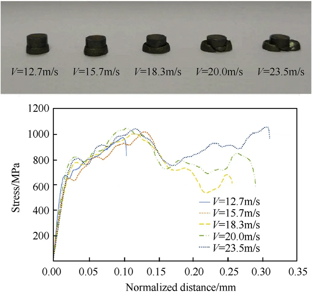
Fig. 5. Stress-normalised distance of the bilayer sample at different impact velocities.
The tested specimen was cut from the middle, and its microstructure was analyzed under an optical microscope. Fig. 9 shows the microstructure of the specimen under the striker velocity of 18.3 m/s.As shown in Fig.9,no damage or crack was present on the interface between the Ti6Al4V and pure titanium. Kwiecien et al.[25]also reported in the steel bilayer specimen no crack and failure observed at the join and only one layer of specimen was responsible for the deformation of the whole specimen.However they observed during the quasi static loading the interface pattern is changing but in the dynamic loading the interface pattern is preserved [25]. In this study also the interface of sample is not changed.Yu et al.[28]found in explosive welded steels sample, failure is occurred at the interface of the sample. The optical microscope images showed adiabatic shear bands occurred at an angle near 45°. Adiabatic shear band started from the edge of the interface with angle of 45°along the maximum shear direction, and the shear adiabatic band travelled in a straight path until it reached the free surface of pure titanium. Shear adiabatic band in pure titanium occurs in strain rates higher than 4500 s-1[38,41], and which shows in the test with impact velocity of the 18.3 m/s the pure titanium section is imposed the strain rate higher than this value.The local strain rate around the adiabatic shear zone can be calculated with the Meyers methods.The local strain rate can be estimated by dividing half of the striker bar velocity with the width of adiabatic shear band[42].Base on this analysis the local strain rate around adiabatic shear band was approximately 6.5×10⁵s-1. Local strain rate calculated through this method is often overestimated from the real value of the local shear strain, although this rate can be used for the rough estimation of local shear strain rate [43]. However, basing on our DIC analysis results(Fig.8),it could be assumed all the deformation occurred on the pure titanium side.Thus,the strain rate on the pure titanium side of the specimen.Table 4 shows the maximum strain and strain rates that occurred in the pure titanium section of the sample at different striker velocities. These results are valid only until the first peak on the stress-normalised displacement curve.Beyond this peak, deformation occurred on the Ti6Al4V.
The compressive load led to inhomogeneous deformation in pure titanium side of the bilayer sample due to the strong welding interface of the pure titanium and Ti6Al4V. The free surface of the pure titanium had larger deformation than the interface surface of the sample.The heterogeneous deformation led to the formation of a cone in the pure titanium side of the bilayer sample under a compressive load(Fig.9(c)).The pure titanium side can be divided to three parts, namely, (1) adiabatic shear band; (2) inner side surrounded by the adiabatic shear band and welded interface and(3) external section of adiabatic shear band, which had a larger deformation. The sections had different microstructures. When dynamic load was applied to the specimen, in the beginning the dislocations are distributed randomly in alpha grain of the pure titanium, by continuing loading, density of the dislocations in the grain are increased. Elongated grains formed because of the rearrangement and movement of the dislocation. By increasing the adiabatic temperature, elongated subgrains are formed, during further deformation elongated subgrains are fragmented. The fragmented subgrains rotated, and equiaxed recrystallised grains formed. Due to this mechanism the small grain is observed in the adiabatic shear band.

Fig. 6. High-speed image shows the failure of the bimetal sample (a) t=0, (b) t=6.66 μs, (c) t=13.32 μs, (d) t=19.98 μs, (e) t=26.64 μs, (f) t=33.3 μs, (g) t=39.96 μs, (h)t=46.62 μs,( i) t=53.28 μs,( j) t=59.94 μs, (k) t=66.6 μs and (l) t=73.26 μs.
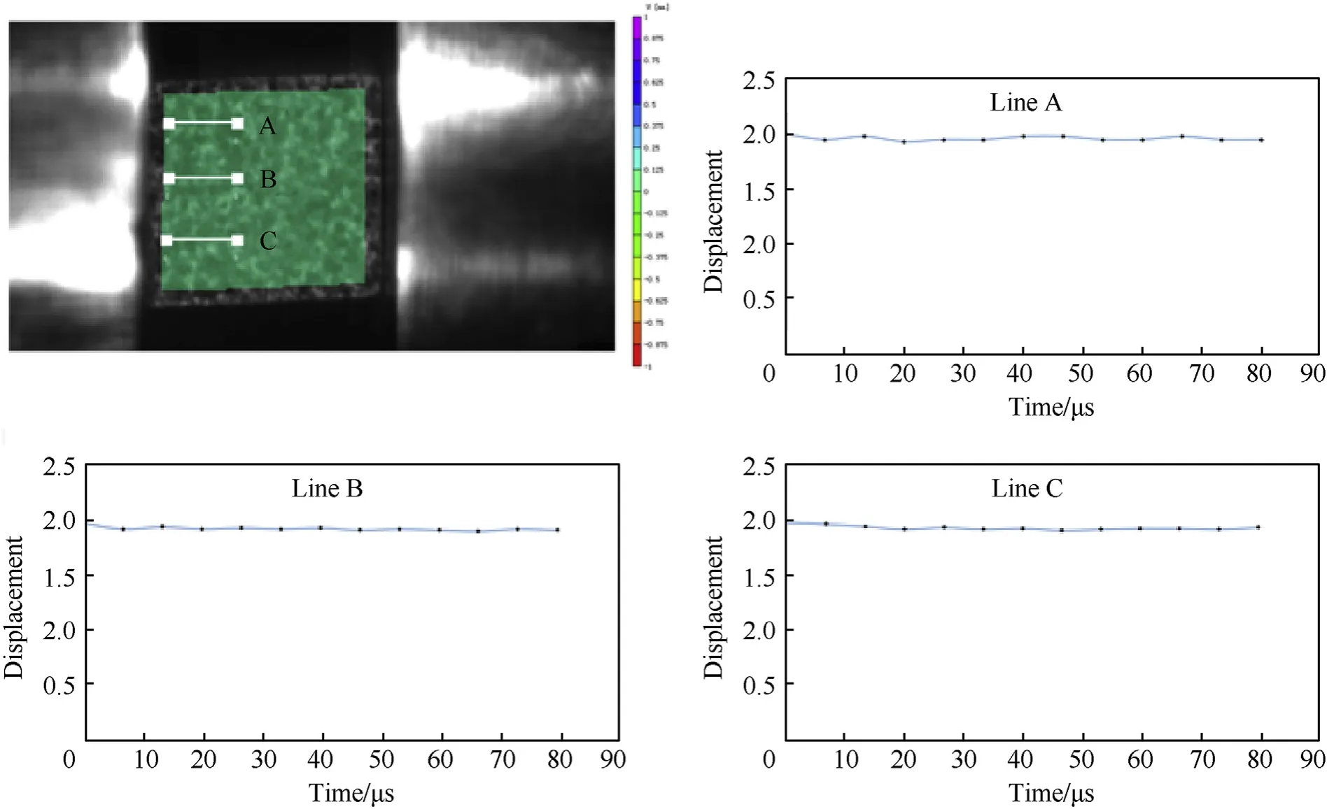
Fig. 8. Displacement in the Ti6Al4V section of the explosion-welded sample.

Table 4 Strain rate in the pure titanium side of sample at different striker velocity.
Fig. 9 (d) shows the adiabatic shear band and crack on the free surface of pure titanium sample at impact velocity of 20 m/s.Dodd and Bai[44]classified the shear band in two distinct groups:ductile shear band and brittle shear band. Elliptical voids form in the ductile shear band,whereas no microvoids form in the brittle shear band.Moreover,no microcrack and microvoid were observed in the shear adiabatic band in the pure titanium layer. That is, a brittle adiabatic shear band occurred in the shear band. Meanwhile, Sun et al. [41] observed voids inside adiabatic shear bands in a pure titanium sample.
The EBSD map of the bilayer sample under the striker velocity of 18.3 m/s are shown in Fig.10.Fig.10(a)illustrates the EBSD map of the inner section of the specimen, where the grains was coarse.However, some deformation twins can be found in this section.Close to the adiabatic shear band the elongated grain toward the shear loading as well as many fine grains are observed. Twinning mechanism plays a great role in dynamic deformation.The inverse pole figure (IPF) colour key for the EBSD maps is shown in Fig.10(b), which presents the grain orientation. The EBSD analysis demonstrates no phase transition(α-β)occurred during the loading.As shown in Fig.10 (c), the external part of the adiabatic shear band has the large deformation. The red dash line presents the approximate boundaries of the adiabatic shear band. In Fig.10 (c), white regions are the demonstrated areas,where no orientation data can be gained because of the large localized deformation or the fine microstructure. Chun et al. [45] observed the α phase adjacent to the shear band was elongated along the shear direction owing to the strong shear deformation,and the elongated α broke into small structures within or close to the shear band. Owing to the severe plastic deformation within the shear band, the areas within the shear band had more points than those near the shear band.
3.3. FEM simulation
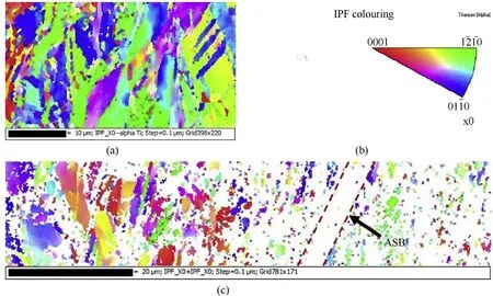
Fig.10. EBSD analysis of the sample under the striker velocity of 18.3 m/s a) at the inner section of the sample, b) the inverse pole figure(IPF) colour key c) adiabatic shear band.

Fig.11. FEM simulation of the sample subjected to the subjected to 12.7 m/s striker velocity.

Fig.12. The comparison of strain signals in the incident and transmitted bars between the experiment and the FEM simulation.
2D models of bilayers sample was created and the simulation was performed using ABAQUS Explicit.Fig.11 shows the contour of von Mises stress on the surface the bilayer specimen subjected to 12.7 m/s striker velocity, at the top right corner, image of the sample at the same time subjected to the same loading is shown.Similar deformation is observed from the simulation and experimental. As the bilayer specimen is not fractured under this condition,failure of the material was not considered in FEM simulation.The simulation results showed that the stress field was not uniform in the specimen.The maximum stress was observed at the interface of the two metals.This finding is in agreement with the DIC analysis results. The edge of Ti6Al4V tolerated the high amount of stress,indicating that the two sides of the sample are not homogenous.Meanwhile,pure titanium tolerated the lower stress but had higher deformation. As shown in Fig.11(b), maximum stress occurred at two zones. One of the zones was the edge of the interface of pure titanium and Ti6Al4V and the other was the cylindrical zone in which start from the interface between the pure titanium and the incident bar.At continuous loading,the size of this cylindrical zone is increasing and narrow area is formed and connected the edge of the interface to the cylindrical zone(Fig.11(c)and(d)).An adiabatic shear band occurred in this narrow area, this result is in good consistency with the microstructure analysis(Fig.9).Fig.12 shows the comparison of strain signals in the incident and transmitted bars between the experiment and the simulation (for better comparison,all the signals were shifted at the same starting point).The agreement between the experiment and the simulation is well.Fig. 13 shows the contour of the strain in direction of impact of bilayers sample.
4. Conclusion
An explosion-welded sample with a flat interface was successfully fabricated and tested under the dynamic loading conditions by the SHPB. Hardness test of samples shows that the microstructure of the explosive welded sample is not changed after the welding and hardness of each side, and it is equal to the original material(370HV for Ti6Al4V and 145HV for pure Ti). The strength of the explosion-welded sample increased with strain rate. The stress curve of the samples showed two peaks at a high strain rate. At high-striker-velocity impact (higher than 18.5 m/s), failure was observed on the pure titanium side of the sample. And it was showed that no deformation occurred in the Ti6Al4V side,and this result is confirmed by the DIC method.The free surface of the pure titanium had larger deformation, the heterogeneous deformation led to the formation of a cone in the pure titanium side of the bilayer sample under a dynamic compressive loading.In high strain rate the failure occurred due to the formation of adiabatic shear band in the pure titanium side(at strain rate higher than 3770 s-1).
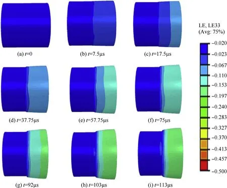
Fig.13. Strain of the bilayer specimen.
Declaration of competing interest
We hereby declare that we have done the experimental design and method,and the collection, analysis,and interpretation of the data appropriately as normally done in any research laboratory.We confirm that the manuscript has been read and approved by all named authors. This manuscript has not been submitted to, nor is under review at, another journal or other publishing venue. The authors declare no conflict of interest.
Acknowledgments
This research was financially supported by National Natural Science Foundation of China with Grant No.11472054 and by the opening project of State Key Laboratory of Explosion Science and Technology (Beijing Institute of Technology) with Grant No.QNKT17-01.
- Defence Technology的其它文章
- Statistical variability and fragility assessment of ballistic perforation of steel plates for 7.62 mm AP ammunition
- Texture evaluation in AZ31/AZ31 multilayer and AZ31/AA5068 laminar composite during accumulative roll bonding
- Local blast wave interaction with tire structure
- Research and development of training pistols for laser shooting simulation system
- Summed volume region selection based three-dimensional automatic target recognition for airborne LIDAR
- A novel noise reduction technique for underwater acoustic signals based on complete ensemble empirical mode decomposition with adaptive noise, minimum mean square variance criterion and least mean square adaptive filter