
Numerical Investigation of a Tube-in-Tube Heat Exchanger Performance Using Ice Slurry as Secondary Refrigerant
2020-08-20 08:02LiYanbo
中阿科技论坛(中英阿文) 2020年7期
Li Yanbo
Abstract: Ice slurry refers to a homogenous mixture of fine ice crystals, water and a freezing point depressant that having much greater cooling capacity than chilled water, can effectively provide the same cooling load with much lower flow rate. Unlike single phase refrigerant, ice slurry is more complex in behavior, so that an accurate evaluation of ice slurry heat exchanger performance requires the knowledge of the thermal and rheological properties of ice slurries. The present study applies VOF (Volume of Fluid) multiphase model to describe the ice slurry flow in a tube-in-tube heat exchanger with considering ice particles melting. The VOF model combined with RNG-based k-ε turbulence model to calculate flow and temperature fields, it was firstly validated by a series experiments reported. Then the validated VOF model was applied to solve the distribution of ice slurry flow, ice particle concentration and temperature in different operating conditions. By running Fluent 6.3, a CFD computer code, a good agreement was found between experimental data and numerical results, within a percentage deviation of ±15% which was in the acceptable limits. And that the VOF model was validated to be a more effective and universal model for describing ice slurry flow, and it may be evaluated rapidly, which was almost impossible experimentally.
About the author:Li Yanbo(1987-), Male,Research direction: Research on mine heat damage and safety technical consultation.
1. Introduction
The role of secondary refrigerants is expected to grow as the focus on the reduction of greenhouse gas emissions increases. Global warming and high energy consumption have lead refrigeration industry to develop an efficient new refrigerant. Ice slurry is considered as a promising two-phase secondary refrigerant which has observed wide application such as food processing and district cooling.
The energy capacity of ice slurries per unit volume is greater than conventional single-phase coolants due to the high latent heat of ice crystals. Therefore, pipe dimensional, pumping energy and operating cost could be reduced substantially. Furthermore, ice slurries also have a good thermophysical and transport properties, unlike single phase fluid, they are more complex in behavior, and hence, the knowledge of those thermal and rheological behaviors are necessary. Because of the many advantages of the ice slurry as a secondary refrigerant, many researchers have investigated its flow and heat transfer characteristics.
Bellas et al(2002) and N?rgaard et al (2005) reported experimental data on plate type heat exchanger and two air cooler coils respectively[1-2]. They concluded that the increase in heat transfer capacity leads to significant reductions in both the size of heat exchangers and the pumping power. Bellas et al(2002) results show that the ice content has a smaller effect on the overall heat transfer coefficient than the flowrate[1]. N?rgaard et al (2005) found that, ice slurry increases the capacity of the air cooler by 5%~10% compared to single-phase media[2]. The pressure drop for ice slurry grows with flow velocity increase, it twice or more as high as for the single-phase media. But this value is almost equal to that of single-phase fluid when flow in low velocity. The optimal ice content was found to be between 20-30 wt% at the inlet.
Thongwik et al(2008) analyzed the heat transfer phenomenon of melting slurry ice on external surface of a cooper helical[3]. The experiments were done with 40%-60% ice slurry in 4.2m length coil and velocity between 0.0149 and 0.0562 kg·s. Authors summarized that, with small coil diameter, high mass flow rate of circulating water and low ice fraction give high heat transfer coefficient.
Shire et al(2009) reported pressure drop measurements in a plate type and a concentric tubular industrial heat exchanger for a 5% sodium chloride aqueous solution containing between 0.15 and 0.6 m3·m-3 of ice[4]. Measured pressure drops were greater than those with water, and rose with increasing ice fraction and flow rate. It was worth noting that blocking events were observed at high ice fractions or large ice crystals present in the ice slurry.
F.Illán and Viedma(2009) studied experimentally the performance of ice slurry in a concentric corrugated tube heat exchanger[5-6]. Authors compare experimental results to theoretical prediction obtained using the correlations proposed in previous paper. It is conclude that ice slurry enhances the heat exchanger behavior, but the increase in heat transfer rate is always lower than 15%. They (2009) also presented an experimental study in a standard fan-coil with ice slurry produced from 9% sodium chloride brine as cooling medium[7-8]. Contrary to the conclusions obtained other types of heat exchangers, ice slurry direct application is not recommended for this design of heat exchanger mainly due to frost formation of ice slurry flow.
Recently, Renaud-Boivin et al(2012) conducted experiments in a shell-and-tube heat exchanger with an ethylene glycol ice slurry flowing in the tubes and hot water in the shell side[9]. The measurements show that the pressure loss, the overall heat transfer coefficient and the effectiveness are maximum when the ice content is maximum.
For ice slurry, the increasing numbers of the published literatures on melting ice slurry have been verified in field of heat exchanger, the main research efforts have been directed at studying experiments on ice slurry behavior in horizontal tubes. It has been found that Computation Fluid Dynamic (CFD) has been applied successfully for simulating various types of heat exchanger in addition, can be used to solve ice slurry thermodynamics and heat transfer problems. But CFD simulation has been treated by only a few authors. Kalaiselvam et al(2009) presented a numerical analysis of tube-fin heat exchangers with ice slurry in HVAC system, authors carried out an optimization process based on the numerical results from different configurations with round and flat tubes and also with plane or louvered fins[10]. The simulation obtained that the increase in heat transfer rate by the usage of ice slurry is 7.4% over conventional chilled water system. But the use of ice slurry increased the pressure drop in heat exchanger. Renaud-Boivin et al(2012) study concerns the pressure-driven flow of ice slurry in a horizontal pipe, the author consider the isothermal steady laminar flow of ice slurry in the entrance region of a horizontal pipe and solve simultaneously the three-dimensional differential equations of motion for the two-phase mixture[9]. Wang et al(2013) applies an Euler-Euler CFD model based on kinetic theory of granular flow to describe the ice slurry flow without considering ice melting[11].The relative errors of the numerical computational were within ±20% which are in the acceptable level, thus the model was applied successfully to solve the distributions of ice slurry flow, ice particles concentration and pressure drop in different pipes.
The attention of this paper is focused on the validation purpose by use of numerical simulations. It involves examine a model of a tube-in-tube heat exchanger geometry using CFD software, FLUNT 6.3,creating a suitable mesh setting up the cases(choosing solves, numerical solution methods, etc.), and comparing results to known data. Moreover, to make a new attempt to apply a VOF CFD model to describe different ice fraction slurry flow in tube-in-tube heat exchanger.
2. Mathematical model
The governing equations for two-dimensional continuity, Navier-Stokes for momentum and energy for unsteady-state in the computational procedure can be written as follows.
2.1 Volume fraction equation
For ice slurry flow where primary phase is liquid, the continuity equation of the ice particles can be written as follows:
where is the mass transfer from carrier fluid to ice particles and is the mass transfer from ice particles to carrier fluid.
The volume fraction αcf of the liquid phase can be computed based on the following constraint:
2.2 The momentum equation
A single momentum equation is solved throughout the domain, and the resulting velocity field is shared among the two phases:
The momentum equation is dependent on the volume fractions of two phases through the properties ρ and μ.
2.3 The energy equation system
Energy equation for VOF model also shared among the phases, is shown below:
where keff is effective thermal conductivity, the VOF model treats energy E as mass-averaged variables:
As in this study with considering ice melting, the energy equation for ice melting is written as:
where H is enthalpy of ice particles, it is computed as the sum of the sensible enthalpy, h, and the latent heat, ΔH
2.4 Material properties
The properties appearing in the transport equations are determined by the presence of the component phases in each control volume. In this study, for example, the density in each cell is given by:
All other properties are computed in this manner.
2.5 Turbulence equation
The mixture turbulence model is adopted to capture the turbulent features of ice slurry flow. Since in the two flow regions having a Reynolds number Re<5000, the (Renormalization group) RNG -based k-ε turbulence model is considered to calculate this low-Reynolds-number condition. The equations for the turbulence kinetic energy k and its dissipation rate ? derived from the Navier-Strokes equation as follows:
Where Gk represents the generation of turbulence energy due to the mean velocity gradient.
3 CFD model validation
In order to solve the above governing equations with the specific boundary conditions, commercial CFD code FLUENT 6.3 has been used, which is based on the finite volume technique.
3.1 Introduced experiment
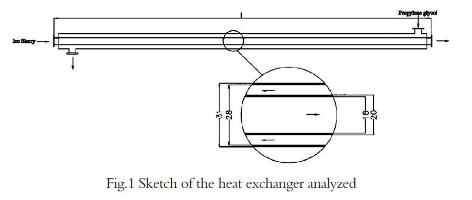
The experimental tests assumed by F.Illán et al in 2012[12]. Fig.1 shows a schematic diagram of a tube-in-tube heat exchanger, it works in counter flow configuration, which was 10m in length (outer diameter 20mm, inner diameter 18mm). The heat exchanger involves two flow regions, cold ice slurries (freezing point is 266K) flowed in the inner tube, with hot solution (9% propylene glycol solution) flowing in the annulus in the opposite direction.
Fig.1 Sketch of the heat exchanger analyzed
In present work, the inlet temperature for propylene glycol solution has been adjusted to obtain outlet temperatures 273K, 298K and 323K. As to obtain similar values of the shell-side and tube-side heat transfer coefficients, flow velocity for ice slurry and propylene glycol solution has been fixed at 1.5m·s and 1.1m·s, respectively, the variation range of other variables analyzed was listed in Tab.1.
Tab.1 Variation range of all variables analyzed
Tube length(m) Direct application Indirect application
10 PG Tin(K) Cip(wt%) PG Tin (K)
279,338.3,399 5,10,15,20,25 277.5,329,387
In order to establish a comparison study between two-phase fluids and single-phase fluids with different cold storage capacity, two types of ice slurry applications have been performed: ice slurry direct application-ice slurry flowing through the tube-side region is compared to ice slurry indirect application-only carrier fluid, without ice particles, flowing through the tube-side region.
3.2 Modeling of heat exchanger
Fig.2 was the illustration of the main computational domain and mashed model of the heat exchanger studied in this paper. The model drawn up was created and meshed by using grid generation package of Fluent, Gambit, then generate the cells for CFD simulation. Because of the high accuracy is required, an unstructured non-uniform grid is chosen to discretize the entire computational domain, and elements refinement has been provided near the tube wall.
It was not possible to perform CFD simulation on the entire heat exchanger due to large number of volumes and calculations required. In this study, the numerical simulation of the heat exchanger was performed by using a two-dimensional double precision symmetry numerical computation technique. The amounts of cells used was 60000; 32000 cells for the modeling of inner fluid, 20000 cells for the annulus fluid and 8000 cells for the copper tube. In order to better validate the flow model, the fluid flow in the tube-in-tube heat exchanger is modeled with three different operating conditions.
Fig.2 Two flow regions of tube-in-tube heat exchanger and computational domain
This ice slurry CFD research was performed to match the experimental conditions. Here we considered that there was no fouling in the modeling, that the thermal resistance and thermal capacitance of the tube walls were negligible and that the heat exchanger did not lose heat to the environment since the propylene glycol solution in the shell-side region is essentially at initial temperature.
3.3 Solving methods
Two phase flow:The two phase flow is more complicated physically than single phase flow. The multiphase flow region employed VOF model in this study, which is the only multiphase model can be used with the solidification/melting model.
Calculation procedure:The numerical simulation of the tube-in-tube heat exchanger is performed with two-dimensional, unsteady-state, turbulent flow system.
Selection of solver:2d-dp pressure based model with implicit formulation is selected due to the geometry has very disparate length scales. The solver conditions are set for unsteady flow with standard wall functions. Adiabatic conditions are considered at the wall.
Selection of viscous model:Since for the entire range of flow rates, The RNG-based k-ε turbulence model is considered due to the Reynolds Number of two regions are over 2000.
Material properties:Properties for carrier fluid and propylene glycol solution are calculated with formulas obtained by polynomial curve fitting of tabulated data published in Handbook on Ice Slurries: Fundamentals and Engineering(2005), the properties are determined by the presence of the component phases in each control volume[13].
The material of tube is copper, the physical properties is taken as constant. For ice particles, the physical properties are summarized as Table 2, when they melts completed, the solid phase change to liquid phase thus the properties are defined as water and taken as constant.
3.4 Boundary condition of calculation
The boundary conditions used in the present study with reference to Fig.2 are defined as follows:
1) The propylene glycol solution enters from right to left, flowing through the shell-side region at a constant flow velocity 1.1m·s and constant temperature of 399K, 338.3K and 279K respectively(for ice slurry indirect application, these values are 387K, 329K, 277.5K,respectively).
2) Ice slurries enter from left to right, flowing through the tube-side region at a constant flow velocity 1.5m·s and constant temperature 266K for all simulations.
3) Symmetrical boundary condition has been applied to the bottom wall due to the symmetry.
4) Wall boundary conditions are used for the top side of the shell and tube.
5) The outflow condition is applied at the two pipes outlet. Specific no slip boundary conditions have been applied to the pipe wall.
3.5 Results verification
The software was run for each model in order to obtain numerical results, then, the numerical analysis performed shows the variations in temperature and liquid fraction distribution along the two flow regions.
The temperature distribution of 25% ice slurry fluid or only the liquid phase used as refrigerant fluid in tube-in-tube heat exchanger for direct(I) and indirect(II) applications are shown in Fig.3.
Fig.3 Temperature contours of ice slurry direct and indirect application for different propylene glycol solution inlet temperature
Tab.2 illustrates the simulation results of absolute temperature drop for these heat exchanger two outlets under different operating conditions. According to these values, 1.5m·s of ice slurry directly application in the heat exchanger allows a reduction in the temperature of 1.1m·s of propylene glycol from 399K to 313.22K, from 338.3K to 295.91K, or from 279K to 273.06K, whereas if for only carrier fluid flows, the temperature of propylene glycol solution only can be reduced from 387K to 322.25, from 329K to 299.77K, or from 277.5K to 272.5K. Totally, it improves the heat exchanger performance over 30% at least.
73 387 64.75 64 1.16%
As the different propylene glycol solution inlet temperature, 25% ice slurry melting processes are not in same as observed in Fig.4. It is shows that there is a slight difference between Figure 5(A) and (B) due to both of the propylene glycol solution temperature are quite higher than ice slurry, ice particles in tube-side region are melt quickly than low propylene glycol solution operating temperature. Figure 5(C), the propylene glycol solution inlet temperature is 279K, which is too close with ice slurry flow temperature, thus the ice slurries are not melted completely, the ice slurry outlet temperature is calculate 270.95K in CFD simulation.
Fig.4 Liquid fraction contours of 25 wt % ice slurry direct application for different propylene glycol solution inlet temperature: (A) 399K (B)338.3K (C)279K
The temperature drop is calculated and compared with the theoretical analysis values reported by F.Illán. The results from numerical analysis are found to exhibit a maximum deviation of 12.87%, which is within the acceptable level.
The results of this comparison show that ice slurry direct application improves heat exchanger behavior in any case. The above figures show that CFD models the temperature values closely and that trends were also very similar. According to the comparison between experiment and simulation, the VOF model gives fairly accurate results and can be used to predict the heat transfer characteristics of ice slurry used in heat exchanger.
4 Simulation results and discussion
Depending on the above-mentioned results it is gathered that the use of ice slurry as refrigerant in tube-in-tube heat exchanger provides a significant heat transfer performance than single-phase liquid. For model developed, ice concentration is one of important design parameters, especially when it applied in different areas due to meet different cooling demands. The variation of ice content will be simulated in order to predict heat exchanger performance and to further ensure the reliability of VOF model, and the numerical calculation process follows the mentioned case, thus to make this modeling be a really useful way for heat exchanger designers to utilize in different applications.
Fig.5 plots numerical results of ice slurry temperature drop in the heat exchanger under different operating conditions. These results correspond to inlet ice concentration varied between 5 and 25wt%, propylene glycol solution flow velocity of 1.1m·s-1 with inlet temperature of 399K, 338.3K and 279K, respectively. For various inlet ice slurry concentrations, it is noticed that the outlet temperature value of propylene glycol solution will become greater with the increasing of inlet ice concentration. VOF Model successfully reveals this common sense. However, the high concentration of ice slurry is not suitable for cooling low temperature product as the ice particles cannot melt completed.
Fig.5. Numerical simulation results for ice slurry and propylene glycol solution outlet temperature decrement of ice content varies between 5 wt% and 25% in three different propylene glycol solution inlet temperature: (A)399K (B) 338.3K(C) 279K
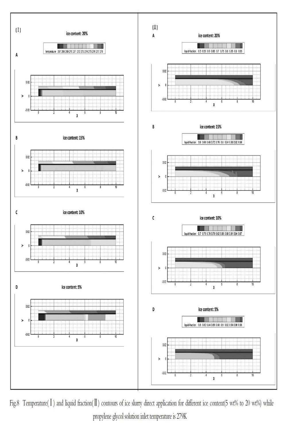
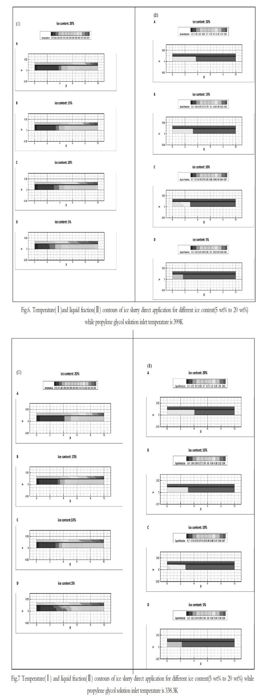
Fig.6 to Fig.8 helps to better understand the results plotted in Fig.5 From the presented results, the inlet ice slurry with high content has a strong influence on tube-in-tube heat exchanger can offing a greater cooling capacity than chilled water and thus ice slurry direct application is recommended.
As the higher ice concentration could keep ice slurry maintaining at a lower temperature for a long time, for ice slurry flow region, the temperature increment is decreased with ice content increasing. The ice slurries melting processes are show in Fig.6(II) Fig.7(II) and Fig.8(II), it seems clear that ice melting rate is inversely proportional to ice content, and ice particles may not completely melted when cooling a lower temperature product.
Fig.6. Temperature(Ⅰ)and liquid fraction(Ⅱ) contours of ice slurry direct application for different ice content(5 wt% to 20 wt%) while propylene glycol solution inlet temperature is 399K
Fig.7 Temperature(Ⅰ) and liquid fraction(Ⅱ) contours of ice slurry direct application for different ice content(5 wt% to 20 wt%) while propylene glycol solution inlet temperature is 338.3K
Fig.8 Temperature(Ⅰ) and liquid fraction(Ⅱ) contours of ice slurry direct application for different ice content(5 wt% to 20 wt%) while propylene glycol solution inlet temperature is 279K
5 Conclusions
Simulations for this project were carried out following as closely as possible the same operating conditions and geometrical configurations of the tube-in-tube heat exchanger as presented in the published literature by Illán (2012). 2D symmetry unsteady simulation was performed and compared to experimental results. The impact of ice concentration on the melting rate and heat transfer rate was studied. The major findings are summarized as follows:
(1)The work done for this study has shown that VOF model could give a reasonable prediction of ice slurry flow melting process and heat transfer performance in tube-in-tube heat exchanger. The numerical simulations were in good agreement with experimental analysis as well as practical experiences where the relative errors were limited to 15% within acceptable level.
(2)The numerical simulation results reveal that ice slurry direct application improves the tube-in-tube heat exchanger performance over 30% for all cases analyzed. It was recommended for this design of heat exchanger due to ice slurry has much greater cooling capacity than single-phase refrigerants.
(3)Heat transfer rate was found to increase with increasing ice fraction. However, high ice concentration slurry flow is not recommended when cooling low temperature fluid due to the unconspicuous cooling behavior.
The comparison between the VOF model results and experimental results will be an indication of the softwares accuracy; it will also provide the researcher the opportunity to become familiar with the software.
References:
[1]Bellas J, Chaer I, Tassou S A. Heat transfer and pressure drop of ice slurries in plate heat exchangers[J].Applied Thermal Engineering, 2002,22(7):721-732.
[2]N?rgaard E, S?rensen T A, Hansen T M, et al. Performance of components of ice slurry systems: pumps, plate heat exchangers, and fittings[J].International Journal of Refrigeration, 2005,28(1):83-91.
[3]Thongwik S , Kiatsiriroat T , Nuntaphan A . Heat transfer model of slurry ice melting on external surface of helical coil[J].International Communications in Heat and Mass Transfer,2008,35(10):1335-1339.
[4]Shire G S F , Quarini G L , Evans T S . Pressure drop of flowing ice slurries in industrial heat exchangers[J].Applied Thermal Engineering, 2009, 29(8-9):1500-1506.
[5]F.Illán, Viedma A. Experimental study on pressure drop and heat transfer in pipelines for brine based ice slurry. Part I:Operational parameters correlations[J].International Journal of Refrigeration,2009,32(5):1015-1023.
[6]F.Illán, Viedma A. Experimental study on pressure drop and heat transfer in pipelines for brine based ice slurry Part II:Dimensional analysis and rheological model[J].International Journal of Refrigeration,2009,32(5):1024-1031.
[7]F.Illán, Viedma A. Prediction of ice slurry performance in a corrugated tube heat exchanger[J].International Journal of Refrigeration, 2009,32(6):1302-1309.
[8]F.Illán, Viedma A. Experimental study of ice slurry performance in a standard fan coil[J].International Journal of Refrigeration, 2009,32(7):1808-1814.
[9]Renaud-Boivin S , Poirier M , Galanis N . Experimental study of hydraulic and thermal behavior of an ice slurry in a shell and tube heat exchanger[J]. Experimental Thermal and Fluid Science, 2012,37(1):130-141.
[10]Kalaiselvam S , Karthik P , Prakash S R. Numerical investigation of heat transfer and pressure drop characteristics of tube–fin heat exchangers in ice slurry HVAC system[J]. Applied Thermal Engineering, 2009,29(8-9):1831-1839.
[11]Wang J, Wang S, Zhang T, et al. Numerical investigation of ice slurry isothermal flow in various pipes[J].International Journal of Refrigeration, 2013,36(1):70-80.
[12]F. Illán, Viedma A. Heat exchanger performance modeling using ice slurry as secondary refrigerant[J]. International Journal of Refrigeration, 2012,35(5):1275-1283.
[13]Kauffeld M, Kawaji M, Egolf P W. Handbook on Ice Slurries: Fundamentals and Engineering[M].Paris:International Institute of Refrigeration,2005:83-121.
