
Study on the influence of the discharge voltage on the ignition process of Hall thrusters
2020-09-14 01:13WenboLI李文博LiqiuWEI魏立秋HongLI李鸿YongjieDING丁永杰JianningSUN孙建宁HaikuoCAI蔡海阔DarenYU于达仁ShangminWANG王尚民andNingGUO郭宁
Plasma Science and Technology 2020年9期
关键词:建宁
Wenbo LI (李文博),Liqiu WEI (魏立秋),2,Hong LI (李鸿),2,Yongjie DING (丁永杰),2,Jianning SUN (孙建宁),Haikuo CAI (蔡海阔),Daren YU (于达仁),2,Shangmin WANG (王尚民) and Ning GUO (郭宁)
1 School of Energy Science and Engineering,Harbin Institute of Technology,Harbin 150001,People’s Republic of China
2 Key Laboratory of Aerospace Plasma Propulsion,Ministry of Industry and Information Technology,Harbin 150001,People’s Republic of China
3 Science and Technology on Vacuum Technology and Physics Laboratory,Lanzhou Institute of Physics,Lanzhou 730000,People’s Republic of China
Abstract
Keywords:Hall effect thruster,ignition process,discharge voltage,PIC simulation,CCD image
1.Introduction
Hall effect thrusters (HET),also known as stationary plasma thrusters (SPTs),are electric propulsion devices under orthogonal electromagnetic fields [1,2].Owing to their simple structure,high specific impulse,and high efficiency,they are often used for various propulsion tasks,such as satellite station keeping and orbit raising [3].The working process of the HET is affected by a lot of factors,including macro discharge parameters(discharge voltage,mass flow rate,and coil currents) [4-6],cathode operating parameters [7-9],external filter circuit parameters [10],discharge channel wall surface materials[11],and acceleration channel structure morphology[12].Among them,the discharge voltage,which is a macro discharge parameter of HET,has a significant impact on the changes in performance parameters,such as the specific impulse of the HET.Therefore,many researchers have conducted in-depth and extensive investigations on the impact of the discharge voltage on the performance parameters of HET.
Variable voltage experiments on SPT-1,D-80,and BHT-1000 HET were carried out by Hofer et al [13].Their results showed that the anode’s specific impulse and efficiency in the HET gradually increased with increasing discharge voltage.Two high-voltage HET SPT-80 and SPT-115 were used to carry out variable-voltage experiments by Kim et al [14].Their results showed that within a certain discharge voltage range,the specific impulse and efficiency of the HET increased with increasing discharge voltage;however,when the discharge voltage was too high,overheating occurred due to excessive heat flow,which significantly reduced the thruster efficiency.The effect of the discharge voltage on the performance parameters of the SPT-1 HET was researched by Manzella et al [15].It was found that for some thruster designs,there were moderate and optimal ranges of anode mass flow and discharge voltage that can maximize the thruster discharge efficiency.The effect of changes in the discharge voltage on the plume divergence angle of the BHT-1000 HET was investigated by Azziz et al[16].It was found that when the discharge voltage was between 300 and 900 V,the thruster plume divergence half-angle was between 68°and 70°;these values indicated that at the voltage range considered,the plume divergence angle of the BHT-1000 HET was not significantly affected by the discharge voltage.The effect of changes in the discharge voltage on the wall loss of the PPSX000-ML HET was systematically investigated by Mazouffre et al [17,18].They found that,for high values of discharge voltage,not only the ion energy and power density but also the wall loss of the discharge channel increased.The effects of changes in the discharge voltage and mass flow on low-frequency oscillations of cylindrical HET were studied by Polzin et al [19-21].Their results showed that the amplitude of the discharge oscillation increased and decreased as the discharge voltage and mass flow rate increased,respectively.Roche et al [22]performed a variable voltage test on an SPT-100 thruster,and their results showed that the thruster had different discharge modes under different discharge voltages.The ignition process is the first step in the safe operation of the HET in orbit[23,24].Once the HET fails to ignite,its optimized performance parameters will have no meaning.As the application of the HET gradually expands from auxiliary propulsion to the main propulsion mechanism,the impact of an ignition failure on the entire satellite platform will be more prominent.During the HET ignition,the emitted electrons are first captured by the stronger magnetic field lines in the thruster exit,and then enter the discharge channel along the magnetic field lines owing to collisions and possible turbulence.In this process,the electrons can gain energy from the axial electric field between the anode and the cathode,and reach the ionization threshold of Xe atoms.The electric field strength changes with changes in discharge voltage,and the energy acquisition process of the electron will be altered accordingly,which has a significant impact on the HET ignition.
Because the HET ignition usually takes several tens of microseconds,and the plasma parameters change drastically during this process,the application of conventional measurement methods,such as probes and spectroscopy,has been limited.Instead,the particle-in-cell (PIC) model and highspeed charge-coupled device(CCD)camera imaging methods have been widely used by researchers.A fully kinetic PIC model was used to investigate the ignition transient of the thruster channel in the HET by Taccogna et al[25].Liu et al improved the PIC model,and studied the evolution of plasma distribution during the ignition process [26].The CCD camera imaging method was used by Vial et al to investigate the dynamic behavior of the HET plume during ignition process[27].It can be found that the observed periodic variations of the plume divergence originate from the displacement of the ionization layer.Ellison et al used a fast camera to obtain an image of the front plume during the HET ignition [28].The results indicated that the azimuthal asymmetry of the plume image was introduced by the hollow cathode.
At present,researchers are primarily interested in the impact of changes in the discharge voltage on the performance parameters of HET,such as the specific impulse and thrust.In previous work [29],the impact of operation parameters on pulse current during HET ignition was studied,and the results indicated that pulse current peak increases with discharge voltage.However,the mechanism that how the change in discharge voltage affects the HET ignition is not clear.Moreover,the change in discharge voltage affects the energy acquisition process of the electrons entering the thruster channel and the ease of establishing of the plasma discharge process when thruster ignition occurs.Nevertheless,there are relatively few studies on these effects.
In this study,we analyzed the impact of changes in the discharge voltage on the HET ignition in detail.First,images of the cathode,the acceleration channel,and part of the plume of a 1 kW HET were obtained.Second,to analyze the effect of changes in the discharge voltage on the characteristics of the plasma parameters during the HET ignition,the ion density and electric potential under different voltages were investigated via a two-dimensional PIC/Monte Carlo collision (MCC) numerical model.The experimental and simulation results clearly show that there is a significant difference between the ion density at the initial ignition phase and propellant avalanche ionization phase under different discharge voltages.The pulse currents at different discharge voltages are also discussed.
The general organization of this paper is as follows.In section 2,the experimental setup and results are given.In section 3,the PIC numerical model is described.In section 4,the results and discussion are showed.In section 5,the conclusions of this work are drawn.
2.Experimental setup and results
2.1.Experimental setup
The vacuum tank used in the experiment had a diameter of 1.5 m and a length of 4 m,equipped with two mechanical pumps,two diffusion pumps,and one roots pump.In our experiment,a 1 kW HET with a boron nitride ceramic channel was used.The ceramic channel had inner and outer diameters of 70 mm and 100 mm,respectively,and an axial length of 50 mm.To understand the impact of changes in the discharge voltage on the ignition process in the acceleration channel,an axial slit (2 mm wide,15 mm long) was formed in the outer ceramic channel wall of the 1 kW HET.The nominal parameters of the thruster were as follows,the mass flow rate of the cathode and anode were 3 sccm and 50 sccm,respectively,the discharge voltage was 300 V,the coil current of the thruster was 2.0 A.A hollow cathode was used to ionize the Xe atoms and neutralize the generated ions.A high-speed CCD camera was used to obtain images during the ignition of the HET with different discharge voltages.The CCD camera used in the experiment captures visible light waveband(350-700 mm).The time interval between images is 14 μs,and the pixel resolution of the images produced is 256×256.To ensure the integrity of the captured ignition image,the CCD camera was installed perpendicular to the thruster axis.Additionally,the CCD camera was placed approximately 500 mm from the central axis of the thruster,to improve the image resolution and reduce the measurement error caused by the camera position.

Figure 1.Pulse currents at discharge voltages of 250 and 300 V.The mass flow rates of the anode and cathode are 50 sccm and 3 sccm,respectively.The solid green dots correspond to the moments when the images given in figures 2 and 3 were obtained.
2.2.Experimental results
Before the HET was ignited,the cathode and anode were supplied with the propellant of 3 sccm and 50 sccm,respectively.A discharge voltage(250 or 300 V)was applied to the anode of HET,the coil current of the thruster was 2.0 A.The cathode was heated by an 8 A current for 3 min,and then the ignition switch was closed for ignition [30].A high voltage was applied to the keeper to pull the electrons out of the cathode,and the entire ignition process followed.Figure 1 shows the pulse currents when the discharge voltages of the HET are 250 V and 300 V,respectively.The solid green dots in figure 1 correspond to the moments when the images given in figures 2 and 3 were obtained.It can be observed from figure 1 that when the discharge voltage is 250 V,the peak value and duration of the pulse current of the thruster are 73.3 A and 87.5 μs,respectively;when the discharge voltage is 300 V,these values are 86.7 A and 80.1 μs,respectively,which are significantly higher than the values corresponding to a discharge voltage of 250 V.It can also be observed from figure 1 that when the HET is successfully ignited,the discharge current gradually switch to a stable discharge at a lowfrequency oscillation state.The current oscillation frequency is of the order of kHz,and the average value is approximately several amperes,which is far lower than the ignition pulse current value.This is because the electric field strength between the cathode and the anode gradually increases as the discharge voltage increases,and the electrons can obtain more energy from per unit distance increases when they enter the acceleration channel,resulting in an increase in the electron temperature and the number of high-energy electrons.Within a certain range,as the electron temperature gradually increases,the ionization rate of the propellant atoms will gradually increase [31];thus,more ions are generated in the thruster channel,which causes the pulse current peak to increase.However,under a constant mass flow,the total number of atoms in the acceleration channel does not change,and as the strength of the axial electric field increases,the ionized ions can be ejected from the channel more quickly,decreasing the duration of the pulse current.
Figures 2 and 3 show images obtained at different points in time during the ignition when the discharge voltages are 250 V and 300 V,respectively.Due to the limitations of the CCD camera lens and photo quality,only the cathode,thruster channel,and part of the plume region are shown in each ignition image.The brightness of the light intensity in the image mainly comes from the excited Xe neutrals during the ignition process and represents the density of Xe+[32,33].Two main differences can be observed between the images at the two voltages.First,at the beginning of the HET ignition (t2=14 μs) at 300 V,the brightness of the cathode exit,thruster exit,and acceleration channel is stronger,and the areas of brightness are larger compared to those at 250 V.This is because the electrons emitted by the cathode are first captured by the magnetic field lines in the strong magnetic field region of the thruster exit,and then drift into or collide into the thruster channel due to the Hall drift.In this process,the electrons gain energy from the axial electric field.When the discharge voltage is higher,the strength of the axial electric field between the cathode and the anode is larger,and the electrons emitted by the cathode obtain more energy during the process of entering the acceleration channel,ionizing more neutral atoms previously collected in the plume region and acceleration channel.The more ions are generated in the plume region and acceleration channel.Therefore,the intensity of the light observed in the plume region and thruster channel is also brighter[30].Second,as the electrons gradually move into the acceleration channel,the electrons energy gradually increases.During the ignition process(t2=28 μs and t3=42 μs) at the higher discharge voltage(300 V),the cathode exit,thruster channel,and plume region are not only brighter,but the areas of brightness are significantly larger compared to the case at the lower voltage.This is because when the discharge voltage is higher,more ions and electrons can be generated at the beginning of HET ignition.As these electrons enter the thruster channel and move toward the anode,they can gain more energy from the stronger electric field,thereby generating more ions and electrons.These newly generated ions will be accelerated toward thruster exit by the axial electric field.Therefore,the ion densities at the acceleration channel and thruster exit are higher,and the light intensity and brightness generated by the collision of ions and electrons are stronger.As can be seen in figure 1,the pulse currents corresponding to the 300 V discharge voltage at these two moments are also larger.
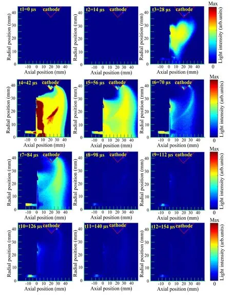
Figure 2.Images of the plasma plume from the HET at different moments of ignition process when the discharge voltage is 250 V.The mass flow rates of the cathode and anode are 3 sccm and 50 sccm,respectively.
3.PIC numerical model
To better analyze the impact of the variation in discharge voltage on the plasma parameters during the HET ignition,a PIC/MCC model established by our team was applied to obtain the variation characteristics of the ion density and electric potential of the HET ignition under different discharge voltages[34,35].Due to the axisymmetric structure of the HET,the circumferential discharge can be considered uniform.The particle velocities in all three dimensions(vz,vr,andvθ) were tracked in our model,whereθindicates the azimuthal direction of the thruster.Due to the evident voltage drop between the cathode and the exit of the HET[8],our PIC model not only includes the acceleration channel,but also part of the thruster plume.

Figure 3.Images of the plasma plume from the HET at different moments of ignition process when the discharge voltage is 300 V.The mass flow rate of the cathode and anode are 3 sccm and 50 sccm,respectively.
The HET used in the model is of the order of 1 kW.The simulation area and boundary conditions are shown in figure 4.After the simulation area is selected and determined,a certain amount number of simulation particles are arranged in the simulation area.The propellant enters the simulation area in a half Maxwell distribution from the anode boundary.When the Xe atoms reach a steady state of flow in the simulation space,electrons are injected from the cathode boundary with a half Maxwell distribution,and ionize and collide with the Xe atoms.The ions are then generated by the collision ionization between the electrons and Xe atoms,inheriting the position information of the ionized atoms.The generated ions are quickly accelerated out of the simulated area by the electric field.The entire ignition process takes place gradually.During the simulation,electrons are magnetized,while ions are not.In the simulation model,mainly collisions between atoms and walls,electrons and atoms,and atoms and atoms are considered.The collisions between atoms and ions are ignored owing to their low collision frequency.In addition,our model does not consider multiple ionization,charge-exchange collisions,and Coulomb collisions.The collisions between atoms and between electrons and atoms are solved via the direct simulation Monte Carlo and MCC methods,respectively [26,34].In our model,the inverse Bohm coefficient is 64 in the plume region and 256 in the acceleration channel.Compared with the externally applied magnetic field,the intensity of the magnetic field induced by the plasma current is small,so it is ignored in the model.The Poisson’s equation is used to evaluate the electric field and potential,and the normal electric field component at the dielectric walls iswhereσis the surface charge density collected by the wall,ε0represents the freespace permittivity andEnis zero on the axis of the HET[26].The potential at the floating metallic magnetic poles is given by the capacity function,and the capacitance is estimated to be C=1×10⁻⁸F.The electrical potential in the free space boundary is 0.

Figure 4.Simulation domain of the HET under different voltages in the PIC model.
The boundary conditions of the particles are as follows.When neutral gas atoms collide with the boundaries of the anode or metal walls,they are re-emitted with the same temperature as the wall or metal walls;when they hit the dielectric walls,the neutrals are re-emitted with the same temperature as the dielectric wall and are uniformly emitted with a half Maxwell distribution.When electrons hit the anode or metal walls,they are deleted,and their charges are transmitted or deposited;when they hit the dielectric walls,they are treated with the secondary electron emission model in[26]as the electron-wall collision model.When ions hit the anode,metal walls,or dielectric walls,they lose their charge,and they are re-emitted as neutral molecules with half of the initial kinetic energy.At the centerline,the particles undergo specular reflection.All the particles are removed if they run through the free space boundary.
The particles’ motion in the model is determined using the following methods.The leapfrog method with secondorder accuracy developed by Boris is used to solve the Newton equations [36];the dynamic alternating direct implicit method is used to solve the potential distribution[37];the particle collisions are solved using the MCC method[38].To achieve suitable calculation accuracy and simulation speed,the method proposed by Szabo et al [39]is employed in our work.Moreover,in order to verify the influence of the zoom factors of the ion and neutral masses and the vacuum permittivity on the simulation results in this work,the HET ignition pulse current under different zoom factors (100,200 and 400) and different increase times of vacuum permittivity(64,100 and 144) are calculated.Figures 5 and 6 show the ignition pulse currents at different zoom factors of the ion and neutral masses and different increase times of vacuum permittivity,respectively.It can be found from figure 5 that although the modification of the zoom factors of the ion and neutral masses in the PIC model will cause the Hall thruster ignition process to start at a different time,when the discharge voltage is high,the thruster pulse current peak is still large and the peak will occur earlier.It also can be found from figure 5 that as the zoom factors of the ion and neutral masses gradually becomes smaller,the time difference between the pulse current peak under different discharge voltages will increase.This is because when the zoom factors of the ion and neutral masses in the PIC model gradually becomes smaller,the mass of ions and neutral in the PIC model will become larger,resulting in a slower movement speed,so the change moment of the dynamic process will be longer.It can be found from figure 6 that as the vacuum permittivity in the PIC model gradually becomes smaller,the moment that the thruster’s ignition pulse current starts to increase will increase significantly,the time difference between when the thruster pulse current peaks occur for different discharge voltages will increase,and the pulse current peak will be significantly reduced (from 140 to 60 A).However,when the discharge voltage is high,the pulse current peak is still large,and the peak will occur earlier.Based on the results in figures 5 and 6,it can be found that although the change of the zoom factors of the ion and neutral masses,especially the change of vacuum permittivity,will evidently change the starting time and pulse current peak of the HET ignition,when the discharge voltage is high,the pulse current peak is still large,the peak will occur earlier in time.This also shows that although the zoom factors of the ion and neutral masses and vacuum permittivity are changed,but the main effect of the change in the discharge voltage on the HET’s ignition process remains unchanged.Therefore,given that the change of the zoom factors of the ion and neutral masses and vacuum permittivity has little effect on the overall change characteristics of the simulation results under different discharge voltages,and in order to achieve suitable calculation accuracy and simulation speed,the zoom factor of ion and neutral masses is chosen as 400 and the increase times of vacuum permittivity is chose as 144 in the model.
The HET used in the model is on the order of 1 kW.The diameter of the inner and outer channels is 70 mm and 100 mm,respectively;the width and length of the plume region are 80 mm and 30 mm,respectively;the width and length of the discharge channels are 15 mm and 16 mm,respectively.In the simulation,the temperature of the anode and the walls of the inner and outer channels is 700 K.The thruster discharge voltages are 250,300,or 350 V,and the mass flow rate is 5.0 mg s−1.
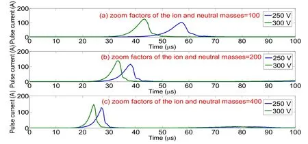
Figure 5.Variation characteristics of ignition pulse current of HET under different zoom factors of the ion and neutral masses during ignition process when the discharge voltages of the HET are 250 and 300 V.(a)Zoom factor of the ion and neutral masses=100,(b)zoom factor of the ion and neutral masses=200,(c) zoom factor of the ion and neutral masses=400.
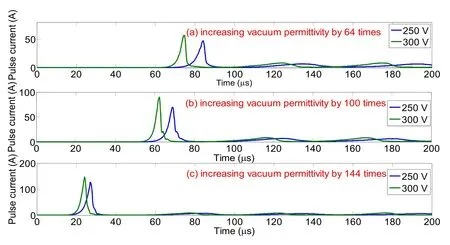
Figure 6.Variation characteristics of ignition pulse current of HET under different increase times of vacuum permittivity during ignition process when the discharge voltages of the HET are 250 and 300 V.(a)Increasing vacuum permittivity by 64 times,(b)increasing vacuum permittivity by 100 times,(c) increasing vacuum permittivity by 144 times.
4.Results and discussion
To better investigate the impact of different discharge voltages on the HET ignition,the distribution characteristics of the plasma parameters at discharge voltages of 250,300,and 350 V were obtained by the PIC model.Figure 7(a)shows the pulse current of the HET at different discharge voltages.It can be found from figure 7 that the pulse current peak is greater than 100 A,which is much higher than the stable discharge current.It can also be found from figure 7(a)that the thruster exhibited a typical breathing oscillation with an oscillation frequency of 20 kHz after the end of the first ignition pulse current,which is similar to the phenomenon observed in[26,27].This result is similar to the experimental results reported in [24].The low-frequency oscillation of the discharge current in the HET is an external manifestation of the domination of the propellant ionization and supplement in the acceleration channel.This neutral atom ionization and supplement process makes atoms and ions behave like predation or breathing effects in nature,accompanied by the movement of the atomic peak surface in this channel,the fluctuation of ion current,and the unstable ionization region[40-43].It can also be found from figure 7(a) that when the discharge voltage increases,the pulse current peak increases,and the peak occurs earlier.

Figure 7.Pulse currents at different discharge voltages of HET.(a) Pulse current at discharge voltages of 250,300,and 350 V,(b)pulse currents during the simulation at discharge voltages of 250 and 300 V.t1 represents the moment of the start of the HET ignition;t2-t4 and t2-t6 represent the enhancement phase of the HET ignition at discharge voltages of 250 V and 300 V,respectively;t5-t7 and t7-t8 represent the weakening phase of the HET ignition at discharge voltages of 250 V and 300 V,respectively;t8-t12 and t9-t12 represent the transitional phase of the HET ignition at discharge voltages of 250 V and 300 V,respectively.
To better analyze the impact of different discharge voltages on the ignition process,the pulse current with discharge voltages of 250 and 300 V was analyzed separately,as shown in figure 7(b).It can be found from figure 7(b) that the duration of the simulated ignition pulse current from the beginning(t1)to the end of the entire ignition process(t12)is about 20 μs,however,the duration of the experimental ignition pulse current under different discharge voltages is about 80-90 μs.There is a significant difference between the two durations,so the selection of the time interval between every two ion densities in the simulation could not be based on the experimental time interval of pulse current.Moreover,during the entire simulation process,it was necessary to compare certain ignition moments that are of particular significance(such as the propellant avalanche ionization moment and the transition phase of the ignition process to the steadystate discharge process) under different discharge voltages.Therefore,different moment points are artificially selected from the pulse current at different discharge voltages,and the distribution characteristics of ion density and electric potential at different discharge voltages corresponding to these moments are calculated.
Figures 8 and 9 show the distribution characteristics of ion density and electric potential at different ignition moments for a discharge voltage of 250 V.The results in figure 8 showed that at the start moment of thruster ignition (t1),the electrons emitted by the cathode are first captured by the magnetic field lines in the strong magnetic field region of the thruster exit,and then enter the thruster channel along the magnetic field lines.During the process,electrons can gain energy in the axial electric field between the cathode and the anode,and collide with and ionize the neutral atoms previously gathered in the plume region and acceleration channel.Owing to the high density of neutral atoms in the acceleration channel,the ion density generated there is also relatively high.Additionally,as the ion density generated at this moment is much lower than the subsequent ignition moments,in order to characterize the ion density distribution characteristics more clearly,the scale of ion density at this moment is set on the order of 1017,whereas the ion density at subsequent ignition moments is set on the order of 1019.As the ignition progress gradually enhanced(from moments t2 to t5),the electrons gradually move to the anode and gain sufficient energy from the electric field.At t6,propellant avalanche ionization occurs,and the ion density and electron density in the acceleration channel reach the maximum.The pulse current also reaches its peak,as shown in figure 7(b).At the same time,as shown in figure 9,as HET ignition further progresses (t2-t6),the potential distribution at the potential drop of the thruster gradually moves from the plume region to the vicinity of the anode.Then,as the Xe atoms in the plume region and acceleration channel are almost completely consumed,the HET ignition becomes weaker (t7-t8),and the ions previously ionized in the acceleration channel are also ejected.The ion density in the acceleration channel is significantly reduced,and the ionization process gradually moves to the anode.At this moment,the potential drop mainly occurs near the anode.It can also be seen in figure 8 that at t8,some ions concentrate in the vicinity of the axis of the computation domain.This is because the magnetic field of the simulated thruster is a magnetically focusing type of field,most of the magnetic lines are inclined toward the centerline of the thruster,so it can be found from figure 8 that when the thruster starts to ignite,the ions tend to focus towards the thruster center axis.Therefore,at t8,there will be a concentration in the vicinity of the axis of the computation domain.At the moments of t9-t12,the ignition process of HET gradually transitions to the stable discharge state in the form of a low-frequency oscillation state(as shown in figure 7 above),at this moment,the discharge current of the thruster is also consistent with the magnitude of steady-state discharge current.Moreover,the ion density that appeared near the axis of the calculation domain at t8 previously gradually decreased with the transition from the ignition process to the steadystate discharge process.
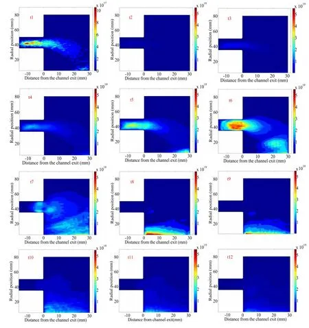
Figure 8.Ion density contours at different ignition moments when the thruster discharge voltage is 250 V.(a) Initial phase (t1),(b)enhancement phase (t2-t5),(c) propellant avalanche ionization phase (t6),(d) weakening phase (t7-t8),and (e) transitional phase (t9-t12).
Figures 10 and 11 show the distribution characteristics of ion density and electric potential,respectively,at different ignition moments when the discharge voltage is 300 V.Because the ion density at t1 moment is lower than at the subsequent moments,the scale of ion density at t1 is set to 1017,and the scale of ion density at subsequent moments is set to 1019.It can be seen in figure 10 that there are two main changes in the ion density change characteristics with the discharge voltage of 300 V,compared to 250 V.First,at t1,the ion density generated in the acceleration channel is significantly higher.This is because when the discharge voltage of the thruster increases,the electrons can gain more energy from the electric field when they move into the thruster channel,thus more high-energy electrons reaching the ionization threshold are generated.Consequently,more ions and electrons are generated when collision ionization occurs with the Xe atoms in the acceleration channel and plume region.Secondly,at t2-t4,the electrons move further towards the anode and gain sufficient energy in the electric field,and at the moment of t4,propellant avalanche ionization occurs.The ion and electron densities,as well as the corresponding pulse current,reach their maxima at this moment.This is because during the HET ignition,when the electron enters the acceleration channel along the magnetic field line,it will gain sufficient energy from the axial electric field.When the discharge voltage of the thruster increases,more electrons are generated at the initial phase of thruster ignition,and more electrons can gain energy from the electric field more quickly.When the electron energy is above the ionization threshold of the Xe atom,the neutral atom begins to be ionized,resulting in an increase in ion density.The electrons generated by ionization will further promote the development of ionization.In the absence of other factors,an exponentially increasing propellant ionization avalanche effect is formed.Therefore,the propellant avalanche ionization process of the HET occurs earlier when the discharge voltage is higher.In this phase,more ions and electrons are generated and a higher peak pulse current is induced.Subsequently,the ignition process gradually becomes weaker (t5-t7),and the neutral atoms previously collected in the thruster plume and channel are almost completely consumed;then,the ionization process of the thruster and the corresponding potential drop mainly occur near the anode,as shown in figure 11.At the moments of t8-t12,the ignition process of HET continues to weaken and gradually switches to stable discharge.At this moment,it can be found from the pulse current shown in figure 7(b)that it is gradually decreasing and tends to a stable discharge state.

Figure 9.Electric potential contours at different ignition moments when the thruster discharge voltage is 250 V.(a) Initial phase (t1),(b)enhancement phase (t2-t5),(c) propellant avalanche ionization phase (t6),(d) weakening phase (t7-t8),and (e) transitional phase (t9-t12).
From the above experimental and simulated results of the variable voltage of the HET,it can be concluded that the discharge voltage,as a macroscopic parameter,has a significant impact on the HET ignition.As the discharge voltage gradually increases,the ignition process changes in two main aspects compared with the ignition process at the lower voltage.First,at the initial phase of ignition process,when the thruster discharge voltage is large,the ion densities generated in the plume region and acceleration channel due to collision ionization is relatively high.Second,when the thruster discharge voltage is large,the propellant avalanche ionization process occurs earlier;the ion and electron densities generated at the moment of avalanche ionization are significantly higher,and the pulse current peak is larger.The main reason for these differences is that the increase in the thruster discharge voltage significantly increases the strength of the axial electric field.The electrons emitted by the cathode can reach the ionization threshold of Xe atoms faster when they enter the acceleration channel and move to the anode.
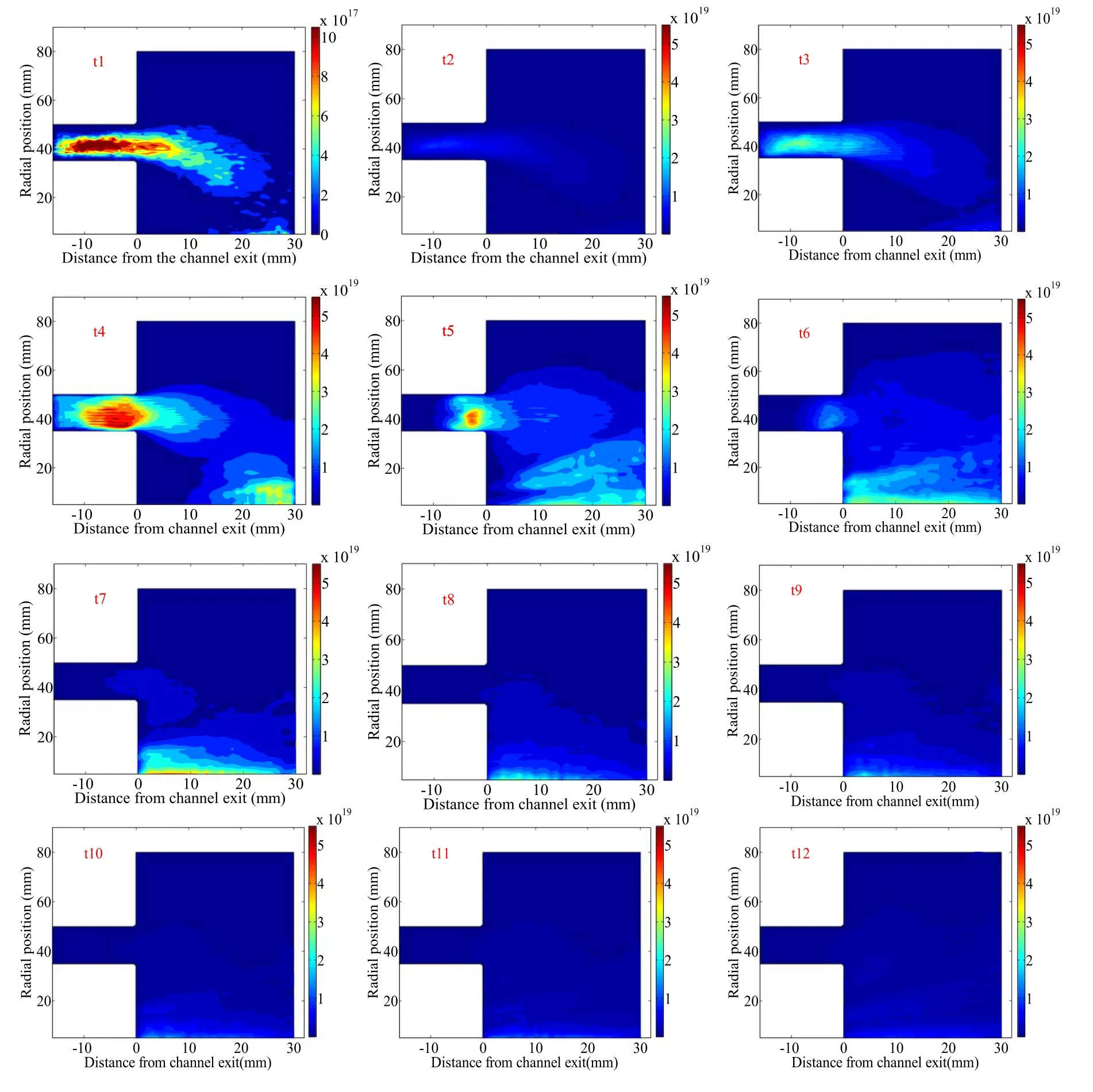
Figure 10.Ion density contours at different ignition moments when the thruster discharge voltage is 300 V.(a) Initial potential contours at different ignition phase(t1),(b)enhancement phase(t2 and t3),(c)propellant avalanche ionization phase(t4),(d)weakening phase(t5-t7),and (e) transitional phase (t8-t12).
5.Conclusion
In this study,a high-speed CCD camera was used to study the characteristics of the changes in acceleration channel and plume characteristics during the HET ignition under different discharge voltages.Then,to understand the impact of different discharge voltages on the plasma parameters of the HET ignition in more depth,the distribution characteristics of ion density and electric potential of different ignition moments under different discharge voltages were obtained by a PIC model.The main results showed that the change in the discharge voltage has an evident impact on the HET ignition in two main aspects.First,at the initial phase of thruster ignition,when the discharge voltage is large,the ion densities generated in the plume region and acceleration channel owing to collision ionization is relatively high.Second,when the discharge voltage is high,the propellant avalanche ionization process begins earlier,and the densities of the ions and electrons generated during avalanche ionization will be significantly higher,and the pulse current peak will be larger.The main reason for these differences is that the increase in the thruster discharge voltage significantly increases the strength of the axial electric field between the cathode and the anode.Therefore,the electrons emitted by the cathode can reach the ionization threshold of the Xe atoms faster when they move into the thruster channel and move to the anode.Although the thruster is easier to ignite at a higher discharge voltage,higher voltages generate larger pulse currents,which cause greater disturbance to the satellite platform,especially low-power ones.In the future,in-depth research will be carried out on this aspect of optimization.
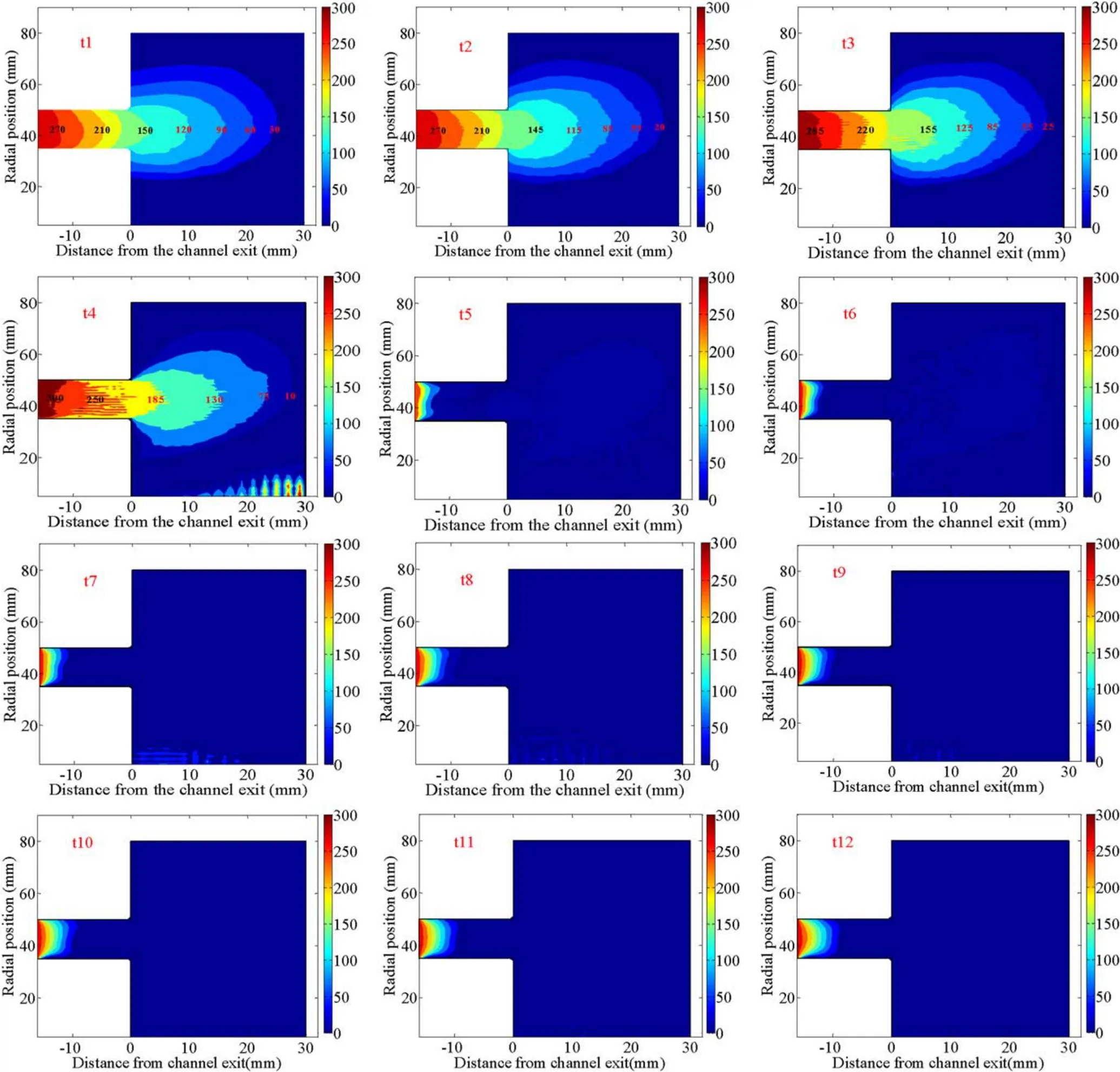
Figure 11.Electric potential contours at different ignition moments when the thruster discharge voltage is 300 V.(a) Initial phase (t1),(b)enhancement phase (t2 and t3),(c) propellant avalanche ionization phase (t4),(d) weakening phase (t5-t7),and (e) transitional phase(t8-t12).
Acknowledgments
This work has been funded by National Natural Science Foundation of China (Nos.51736003 and 51777045),the Foundation of Science and Technology on Vacuum Technology and Physics Laboratory of Lanzhou Institute of Physics (No.6142207190305),and the Science and Technology Innovation Projects of Hunan Province(Project No.2018RS3146 and Project No.2019RS1102).
猜你喜欢
小小说月刊(2022年19期)2022-10-20
民间故事选刊(2022年19期)2022-10-19
苏区研究(2022年4期)2022-08-13
润滑与密封(2020年9期)2020-12-10
阅读(快乐英语中年级)(2019年5期)2019-09-10
检察风云(2017年15期)2017-09-12
海峡姐妹(2017年4期)2017-05-04
绿色中国(2017年2期)2017-03-28
视野(2016年14期)2016-09-28
课程教育研究·学法教法研究(2016年13期)2016-06-29
 Plasma Science and Technology2020年9期
- Plasma Science and Technology的其它文章
- Impact of exterior electron emission on the self-sustaining margin of hollow cathode discharge
- Research on the neutralization control of the RF ion micropropulsion system for the‘Taiji-1’ satellite mission
- On the heating mechanism of electron cyclotron resonance thruster immerged in a non-uniform magnetic field
- The plume diagnostics of 30 cm ion thruster with an advanced plasma diagnostics system
- Performance of a 4 cm iodine-fueled radio frequency ion thruster
- Experimental investigation on the plasma morphology of ablative pulsed plasma thruster with tongue-shaped and flared electrodes