
Reflectionless spatial beam benders with arbitrary bending angle by introducing optic-null medium into transformation optics∗
2021-03-19 03:20FeiSun孙非YiChaoLiu刘一超YiBiaoYang杨毅彪HongMingFei费宏明ZhiHuiChen陈智辉andSaiLingHe何赛灵
Chinese Physics B 2021年3期
Fei Sun(孙非), Yi-Chao Liu(刘一超),†, Yi-Biao Yang(杨毅彪), Hong-Ming Fei(费宏明),Zhi-Hui Chen(陈智辉),‡, and Sai-Ling He(何赛灵)
1Key Laboratory of Advanced Transducers and Intelligent Control System,Ministry of Education and Shanxi Province,College of Physics and Optoelectronics,Taiyuan University of Technology,Taiyuan 030024,China
2National Engineering Research Center for Optical Instruments,Center for Optical and Electromagnetic Research,Zhejiang University,Hangzhou 310058,China
Keywords: spatial beam benders,optic-null medium,transformation optics
1. Introduction
A spatial beam bender can steer the incident beam by a fixed angle that is the same for various incident angles,which has applications in various fields, including imaging systems,free space communication(e.g.,acting as a relay system between two communication points),[1]and laser ranging (e.g., measuring non-straight-line distance). The spatial beam bender can be designed according to the geometrical optics by solving the generalized Luneburg inverse problem.[2-5]However, the spatial beam bender designed by the geometrical optics requires inhomogeneous medium and would encounter a problem of singularity in the center, which limits its applications. Another way to design the spatial beam bender of arbitrary bending angle is transformation optics (TO), which provides a unique way to control electromagnetic waves through transformation media designed by various coordinate transformations.[6-8]Based on the form-invariant of Maxwell’s equations and material interpretation,TO links both electromagnetic fields and media between the reference space and real space through the coordinate transformation.[9-13]The spatial beam bender designed by TO is often inhomogeneous and anisotropic, which is still challenging to realize. Choosing a suitable coordinate transformation can simplify the required materials. For example, optical conformal mapping can be utilized to eliminate the anisotropy of the spatial beam benders.[8]However, spatial beam benders designed by an optical conformal mapping still have the same problem as the beam benders designed by the geometrical optics: complex index gradients (inhomogeneous materials). One effective way to eliminate the inhomogeneity in TO is to choose an extreme coordinate transformation,which often leads to highly anisotropic homogeneous medium(often referred to as optic-null medium or optical nihility medium).[14-19]In this study, we use an extreme finite embedded coordinate transformation and introduce an opticnull medium to design a reflectionless spatial beam bender with an arbitrary bending angle by a homogenous anisotropic medium. The schematic diagram of the designed spatial beam bender is shown in Fig.1. The designed beam bender is of a homogenous anisotropic medium(optic-null medium)in the three-dimensional (3D) pillar of fan-shaped section. The bending angle β of the device is determined by the geometrical central angle of the fan-shaped region. Next,we use transformation optic to derive the required medium in the fan-shaped region,and verify the performance of the beam bender numerically.
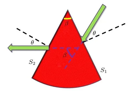
Fig.1. Schematic diagram of β-degree spatial beam bender(red color),with the angle between the incident beam and the steered beam being a fixed angle of β for arbitrary incident angle θ.
2. Theoretical design
We first design a spatial beam bender by finite embedded transformation and then simplify its materials by choosing an extreme parameter. We use the following coordinate transformation to design a spatial beam bender:
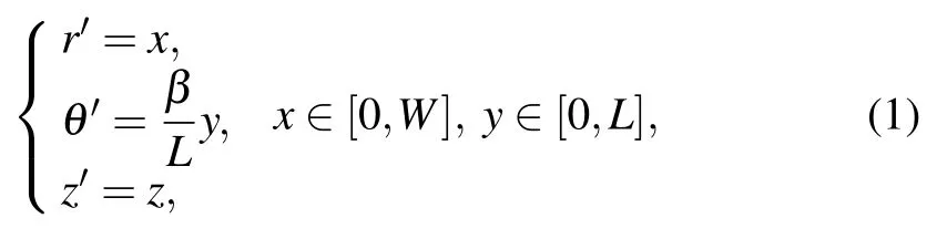
where W and L are the width and length of the rectangular coordinate grids, respectively, β is the bending angle, (x, y,z) and (r′, θ′, z′) are coordinates in the reference space and the real space, respectively. The rectangular coordinate grids within the rectangular region in the reference space are transformed into curved grids within the fan area in the real space(see Figs. 2(a) and 2(b)) by the coordinate transformation of Eq.(1). The coordinate transformation relation in Eq.(1)can also be expressed as
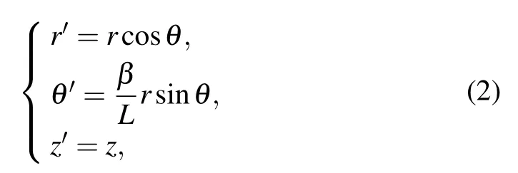
where all coordinate variables are expressed in cylindrical coordinate. The corresponding transformation matrix is
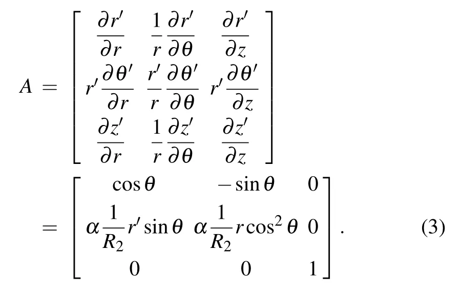
The relative permittivities and permeabilities between the two spaces can be related by TO:[9-11]

where ε =µ =1(free space in the reference space)and A is the transformation matrix in Eq.(3). The required medium of the spatial beam bender can be calculated by using Eqs. (3)and(4)as follows:

which is expressed in the cylindrical coordinate system. The required medium of the spatial beam bender given by Eq.(5)is inhomogeneous and anisotropic,which limits its realization.One effective way to eliminate inhomogeneity in TO is to introduce an optic-null medium.[17]By choosing L →0,the spatial beam bender in Eq.(5)will reduce to
which is an optic-null medium with the main axis along the θ direction. As L →0, the transformation relation between coordinate grids in Fig.2 also changes. When L →0,the rectangular region with length L,width W and infinite height along z direction in the reference space is reduced into a surface.Since the fan region in the x′-y′plane of the real space filled with the optic-null medium in Eq.(6)corresponds to a line but not a region in x-y plane of the reference space, the medium in the fan region is optic-null medium(hence the name).
The most interesting function of optic-null medium is to directionally project identically the EM field distribution from one surface to its equivalent surface along its main axis.[17]This special feature of optic-null medium has been used to design many novel optical devices[11,17]and also extended to other physical fields/waves.[20-22]Since two sides of the fan region S1and S2linked by an optic-null medium in the real space correspond to the same line in the reference space,they are often treated as the equivalent surfaces. The incident electromagnetic field distribution on one side S1of the fan region filled with the optic-null medium described in Eq.(6)is identically project onto the other side S2: the angle between the incident beam and the input surface S1equals the angle between the steered beam and the output surface S2(i.e.θ1=θ2,see Fig.2(c)),which means that the bending angle β between the incident beam and steered beam is the same as the central angle of the fan region.
The spatial beam bender by optic-null medium has the special features as follows. (i)No matter how the incident angle θ1changes,the bending angle between the incident beam and the steered beam keeps the same as the geometrical central angle β of the fan region filled with the optic-null medium designed according to Eq. (6). (ii) The bending angle can be designed from 0◦to 180◦by simply choosing the corresponding geometrical central angle β without changing the required material in the fan region. For various bending angles, the medium in the fan region keeps the same (i.e., the optic-null medium with the main axis along the tangential direction in Eq. (6)). (iii) The reflectivity of the designed spatial beam bender is nearly zero if the spot size of the incident beam is smaller than the size of the device’s input surface. (iv)The geometrical shape of the spatial beam bender can be transformed from the fan shape to other shapes based on the directional projecting feature of optic-null medium. Next,we perform some numerical simulations with COMSOL Multiphysics to verify the above features of the designed beam benders.

Fig.2. Coordinate grid relations between(a)reference space and(b)real space from Eq.(1). (c)Angle bending function of optic-null medium as shown in Eq.(6).
3. Simulation results
Numerical simulations in Fig.3 verify that the function of the spatial beam bender can work for various incident angles.It also means that all Fourier components of the radiation source can be steered by a pre-designed fixed angle β at the output surface of the spatial beam bender.Hence,the designed spatial beam bender can also be used to create a rotated virtual transmission image (see Fig.4(a)). The numerical results in Figs.4(b)and 4(c)show that the field distribution near the exit surface (outside the device) is just like the continuous input field distribution near the input surface in the corresponding region inside the device.
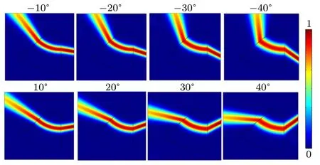
Fig.3. Normalized amplitude of electric field distribution when the incident angle varies from −40◦to+40◦. The bending angle is β =45◦. The Gaussian beam is incident from the right on the right side of spatial beam bender.

Fig.4. (a) Schematic diagram to achieve rotated imaging by the designed spatial beam bender. Numerical simulation results to verify the rotated imaging function of the designed beam bender: normalized electric field distribution is plotted when(b)one or(c)two point sources are in front of the input surface of the spatial beam bender(β =90◦),respectively.
As two surfaces(orthogonal to the main axis of the opticnull medium) linked by the optic-null medium perform as equivalent surfaces, the bending angle β of the spatial beam bender can be designed arbitrarily from 0◦to 180◦. Figure 5 shows the bending effect of the designed spatial beam bender when the bending angle β changes from 15◦to 135◦.Note that the medium inside the spatial beam bender keeps unchanged (the optic-null medium in Eq. (6)) when bending angle β varies as shown in Fig.5.
Note that the coordinate transformation in Eq. (1) is applied to a finite embedded region(not a continuous transformation in the whole space),which is referred to as the finite embedded transformation.[23]The discontinued coordinate transformation may lead to some reflections at the output surface of the device designed by the finite embedded transformation,[24]which influences the efficiency of the device. The continuous metric between the transformed medium and background is a necessary condition to achieve a reflectionless device by finite embedded transformations.[23]This condition is satisfied for the spatial beam bender designed by the coordinate transformation defined by Eq. (1). Numerical simulations in Figs. 3 and 5 (the amplitude of electric field) show that there are no fringes around the input surface of the device,which also verifies that the design spatial beam bender is reflectionless. Numerically calculated results in Fig.6(a) show that the reflectivity of the designed spatial beam bender keeps very low for all incident angles and bending angles. The effective spot size of the incident Gaussian beam (with a fixed width) onto the device increases as the incident angle increases (some parts may go beyond the edge of the device), which leads to slight increase in reflectivity when the incident angle increases.

Fig.5. Normalized amplitude of the electric field distribution when bending angle β varies from 15◦to 135◦. Gaussian beam is normally incident onto the input surface of spatial beam bender from the right side.
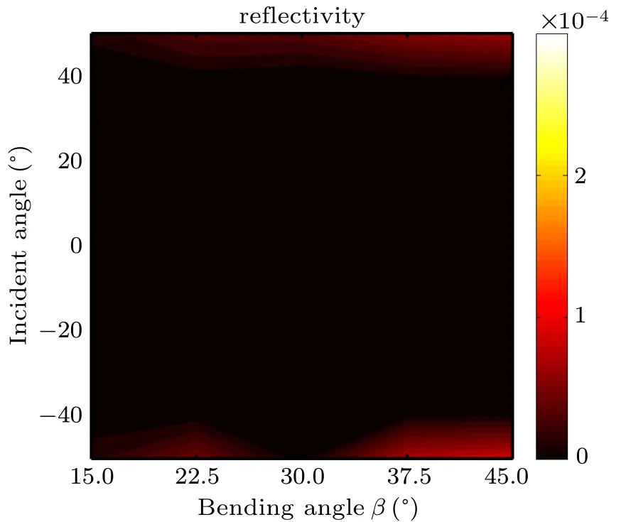
Fig.6. Normalized amplitude of electric field distribution when bending angle β varies from 15◦to 135◦. Gaussian beam is normally incident onto the input surface of spatial beam bender from the right side.
Optic-null medium with extreme material parameters can be realized by a metal plate array whose length satisfies the Fabry-P´erot resonance condition,[15]and a metal slab with periodic sub-wavelength holes working around the cut-off frequency,[14,18]or metal plates inside zero-refractive-index background medium.[25-27]However,there are few studies on how to reduce the extreme material requirement of the opticnull medium. By choosing L →0,the inhomogeneous spatial beam bender in Eq.(5)changes into a homogenous optic-null medium in Eq.(6).For numerical simulations in Figs.3-6,we choose the optic-null medium in the following forms:
where Δ (very small number) is chosen to be 0.001. The smaller the Δ in Eq.(7)the better the performance of the spatial beam bender,as theoretically predicted,but the tougher to realize it is. Numerical result in Fig.7 shows that if Δ ≤0.01,the reduced optic-null medium in Eq.(7)can perform as a spatial beam bender whose bending angle is determined almost by the central angle β of the fan region. If 0.01 <Δ <1,the reduced homogenous beam bender in Eq. (7) can still act as a spatial beam bender. However, as Δ increases, the actual bending angle in the far field decreases linearly(smaller than the central angle β of the fan region) in Fig.7(b). Our numerical results show that this linear relation can be expressed as

Here,β is the central angle of the fan region and β′is the actual bending angle of the reduced device when the medium in fan region is expressed as Eq. (5) with 0.01 <Δ <1. This means that we can use the reduced optic-null medium (homogenous low-anisotropic material in Eq. (7)) to achieve the predictable spatial beam bending effect by Eq.(8). Note that the spatial beam bender by the reduced optic-null medium in Fig.7(a)is still reflectionless.
The proposed spatial beam bender can be realized by layered metal plates and dielectrics(see Fig.8(a)).The separation of metal plates should be on the order of subwavelength, and the orientation of metal plates should consist with the main axis of optic-null medium, which performs as subwavelength channel to guide the EM wave directionally with respect to the TM waves.[28]The dielectrics are filled within each subwavelength channel to reduce the reflection.The relevant relation is as follows:

where nkis the refractive index in the k-th channel,m is a positive integer, Lkis the geometrical length of the k-th channel,and λ0is free space wavelength. Figure 8(b) shows the numerical simulation result when the 90◦spatial beam bender is realized by the layered metal plates and dielectrics, which shows very good beam bending effect as predicted.
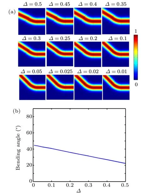
Fig.7. (a)Normalized amplitude of electric field when beam bender is realized by reduced optic-null medium in Eq.(5)for various Δ values. (b)Relation between Δ and bending angle in far field produced by reduced optic-null medium of the designed beam bender. The geometrical shape and central angle of fan region keep unchanged(β =45◦).

Fig.8. (a) Layered metal plates (thin black lines) and dielectrics ranging from 1 to 2.3 indicated by different colors,are utilized to realize 90◦spatial beam bender. (b) Normalized amplitude of magnetic field’s z components distribution when Gaussian beam is normally incident onto the input surface of spatial beam bender from the right side.
Note that the spatial beam bender is different from the waveguide benders/couplers, which can be designed by various methods.[29-32]For example, optical conformal mapping can be utilized to design waveguide bender of various shapes.[29]However,waveguide benders/couplers,which perform as a connector between two waveguides,cannot directly be applied to free space beam (some unexpected scattering at the boundaries may appear). Previous waveguide benders/couplers designed by TO or other methods often need inhomogeneous materials, or geometrical-dependent materials (i.e., the materials are required to change when the size and shape of the device change). Spatial beam bender made of optic-null medium proposed in this study can also be used in the waveguide environment,which only needs homogenous geometrical-independent material.
4. Conclusions
In our previous studies on optic-null medium,[11,22]we used directional projecting feature of optic-null medium to design various optical devices directly (this method is referred to as optical surface transformation), where no mathematical calculations are involved. In this study, reflectionless spatial beam bender with an arbitrary bending angle is designed by TO through the detailed calculations, and then further simplified by introducing an optic-null medium during the finite embedded coordinate transformation. What is different from previous applications of optic-null medium is that the spatial beam bender in this study is designed to steer the incident beam of arbitrary incidence angle by a fixed pre-designed bending angle β without any reflection,which can also be utilized for implementing the rotated virtual transmission imaging. For various values of bending angle β of the designed beam bender(simplyequal to the geometrical central angle of the device),the required material of device is the same(i.e.the homogenous anisotropic optic-null medium in Eq. (6)). We also study how the device performance changes as the degree of optic-null medium’s anisotropy decreases. The numerical simulations show the reduced optic-null medium(with low degree of anisotropy) can still keep a certain performance (see Fig.7 and Eq. (8)). The spatial beam bender can also be realized by the reduced optic-null medium with low anisotropy(0.01 <Δ <1 in Eq. (7)), which is easier to realize than the ideal optic-null medium in Eq.(6). The reduced spatial beam bender is also a reflectionless device,whose bending angle can be predicted from the linear relation in Eq.(8). The proposed spatial beam bender may have applications in free space communication,rotational imaging,laser ranging,etc.
- Chinese Physics B的其它文章
- Transport property of inhomogeneous strained graphene∗
- Beam steering characteristics in high-power quantum-cascade lasers emitting at ~4.6µm∗
- Multi-scale molecular dynamics simulations and applications on mechanosensitive proteins of integrins∗
- Enhanced spin-orbit torque efficiency in Pt100−xNix alloy based magnetic bilayer∗
- Soliton interactions and asymptotic state analysis in a discrete nonlocal nonlinear self-dual network equation of reverse-space type∗
- Discontinuous event-trigger scheme for global stabilization of state-dependent switching neural networks with communication delay∗