
Micro-scale photon source in a hybrid cQED system∗
2021-05-06 08:54MingBoChen陈明博BaoChuanWang王保传SiSiGu顾思思TingLin林霆HaiOuLi李海欧GangCao曹刚andGuoPingGuo郭国平
Chinese Physics B 2021年4期
关键词:思思
Ming-Bo Chen(陈明博), Bao-Chuan Wang(王保传), Si-Si Gu(顾思思), Ting Lin(林霆),Hai-Ou Li(李海欧), Gang Cao(曹刚),†, and Guo-Ping Guo(郭国平),3,‡
1Key Laboratory of Quantum Information,CAS,University of Science and Technology of China,Hefei 230026,China
2CAS Center for Excellence in Quantum Information and Quantum Physics,University of Science and Technology of China,Hefei 230026,China
3Origin Quantum Computing Company Limited,Hefei 230026,China
Keywords: SQUID array resonator,double quantum dot,electron–photon coupling,photon emission
1. Introduction
As a fundamental physics process in nature, photon–atom interaction is studied in cavity quantum electrodynamics (QED) at the most elementary approach where a single photon interacts with a single atom at single quantum energy level.[1]It has attracted extensive interest in various experimental platforms.[2–5]Coherent photon source is an important application of cavity QED, which is generated from the population inversion of few atoms in a cavity via stimulated emission.[6]Few-emitter lasers have been demonstrated in atomic[7]and solid-state systems.[8–11]
Semiconductor quantum dot (QD) system, with good scalability[12,13]and compatibility with conventional industrial fabrication,[14]is a promising candidate for solid-state quantum information processor. Experiments on photon emission from biased double quantum dots(DQDs)were also performed and measured using microwave resonators.[15,16]More recently, great progress has been achieved in DQD-resonator hybrid circuit QED systems that studies the electron–photon interaction between superconducting resonators and DQD-defined qubits.[17–20]Benefiting from high impedance resonators,[21,22]these circuit QED systems achieve large electron–photon coupling rates and enable high-sensitivity probe of electron dynamics.[23–26]
Here, we report the observation of reflection gain in a hybrid cQED system which results from photon emission by applying a DC voltage bias across the semiconductor double quantum dots.[15]The tunneling between DQD charge states leads to the emission of microwave photons and phonons simultaneously,[27]probed by a high-impedance superconducting resonator. By comparing the reflection spectrum measured in Coulomb blockade with that measured at the hot spot,we distinguish the photon emission from the frequency shift.The study here provides a possibility to realize a coherent photon source in a semiconductor quantum system.[28]
2. Experimental setup
Our device is made up of a 1/4 wavelength superconducting resonator and a gate-defined DQD,as shown in Fig.1(a).The resonator consists of an array of superconducting quantum interference devices (SQUIDs)[29]with a tunable resonance frequency fr. Each SQUID contains two Josephson junctions and its inductance is flux-dependent. In this paper, we set the resonator frequency fr=6.758 GHz with a total decay linewidth,internal loss rate,and external loss rate(κ,κi,κe)/2π =(58.9,36.9,22.0) MHz. Due to the high inductance of the SQUID array,the impedance of the resonator Zr≈1 kΩ, which is far beyond 50 Ω of the typical coplanar waveguide.
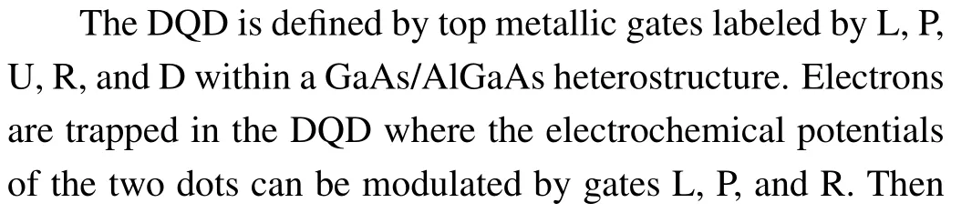


Fig.1. (a)Scanning electron micrograph of the device. The electrode gates L, P, U, R, and D define the DQD by applying negative bias. A DC voltage VSD can be applied to the source–drain to drive the DQD. The right plunger gate is connected to the SQUID array resonator. The resonator is used to detect the DQD charge state by microwave tone through the drive line.(b)Charge stability diagram of the DQD measured by the SQUID array resonator for VSD=0. The transition between the DQD and source–drain is clearly observed,as well as the interdot transition line with a positive slop.
To couple the DQD to the resonator,the right plunger gate straightforwardly connects to the voltage antinode of the resonator. This hybrid system can be described by the Jaynes–Cummings Hamiltonian[1]
where σzand σ±are the Pauli matrices in the DQD eigenstate basis, ωr=2π fris the resonator frequency, a and a†are the photon creation and annihilation operators,and gc=g0·2tc/Ωis the effective coupling strength with the electron–photon coupling rate g0/2π ≈57 MHz which is obtained by fitting the data to the input–output theory.[30,31]
Due to the coupling between the DQD and the resonator,a change of the DQD charge state results in a modification of the susceptibility of the resonator that causes the shift of effective frequency ∆fr. In the dispersive limit,where the energy difference between the resonator and qubit,∆=Ω −hfr,is much larger than the coupling rate gc, the frequency shift∆fr∝(gc/∆2)σz. Therefore, the DQD charge state can be obtained according to the resonator behavior. In our experiments, we probe the DQD by sending a microwave tone into the SQUID array resonator and measuring the reflected signal. We set the probe frequency fp= fr, so the frequency shift leads to an augment in the reflection |S11|. Benefiting from the high impedance resonator,the large electron–photon coupling strength enables high-sensitivity probe in our hybrid cQED system.
To perform the experiments, the hybrid device is cooled in a dilution refrigerator with a base temperature of ∼25 mK.The microwave drive is generated from a vector network analyzer with a power of −30 dBm, passing through an attenuation of ∼70 dB before reaching the sample.Figure 1(b)shows the stability diagram of the DQD for source–drain biasVSD=0 in the many-electron regime measured in the resonator reflection|S11|.The DQD configuration labeled by(m,n)represents m(n)electrons in the left(right)quantum dot.

The probe frequency fpis set on resonance with the resonator,so the measurement of reflected signal|S11|is expected to increase at these tunneling lines. However,except the interdot tunneling,all the charging lines have a smaller reflectance compared to that in Coulomb blockade. This can be explained by the fast decay rate of the charge states induced by the reservoir. The DQD–reservoir electron transfer opens an additional dissipation channel for the hybrid device which deteriorates the resonator quality when the photon interacts with the electron, leading to a larger resonator linewidth and a deeper valley-shaped spectrum at these tunneling lines.
3. Photon emission near hot spot
Generally,a coherent emitter consists of a gain medium,a pumping source, and a resonator. In this cQED hybrid system,the DQD serves as the gain medium. By applying a DC voltage bias across the DQD as a steady pumping source,stimulated photon emission is enabled.
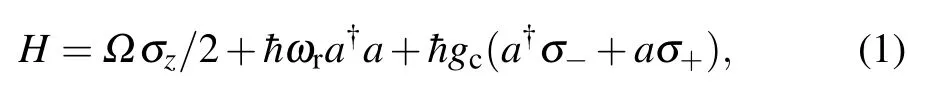
Fig.2. (a) The gain measured as a function of VP and VR with a source–drain bias VSD =0.5 mV. The upper one of the FBTs is outlined with a dashed triangle and the lower one with a dotted triangle. The enhanced reflectance regime with G>1 is indicated by a solid arrow within the FBT while the suppressed reflectance regime with G<1 is indicated by a dashed arrow. (b)A line cut for VP =−944 mV along the vertical line in(a). The peak corresponds to the photon emission while the left valley corresponds to the photon absorption. (c)Schematic diagram of the sequential tunneling dynamics. Electrons jump downhill from the drain to the source and simultaneously emit a microwave photon during interdot tunneing. If the photon frequency matches the resonator frequency, it is caught and stored in the resonator.
For a clear comparison between the photon emission and photon absorption, we measure the reflection spectrum |S11|along a vertical line in Fig.2(a) across the upper FBT, as shown in Fig.2(b).The spectrum displays two valleys and one peak. The right valley corresponds to the DQD–reservoir tunneling,while the left valley is the result of photon absorption during the interdot transition. The peak reaches maximum of G=1.1 indicated by a solid arrow due to the photon emission from the DQD.
4. Distinguish from frequency shift
In our experiment setup, we take advantage of a 1/4 wavelength SQUID array resonator to couple a semiconductor DQD system and probe the dynamics of the driven DQD.The frequency shift caused by the charge transfer also leads to an increased response of the reflection resonator as explained above, different from the transmission signal of a 1/2 wavelength coplanar waveguide.[15,16]Therefore, we need to distinguish whether the gain observed at the hot spot stems from photon emission or frequency shift.


Utilizing the spectra comparison method, we are able to distinguish the photon emission from the enhanced reflected signal at the spot hot. Next, we change the bias window by modulating the source–drain bias from −0.4 mV to 0.4 mV as shown in Fig.4. The different DC bias voltage directions lead to different shapes of FBTs. The larger voltage,the larger area of bias triangles, and the larger area of hot spot. However,the gain measured for|VSD|=0.4 mV is smaller than that for|VSD|=0.2 mV.This can be explained by the influence of large DQD–reservoir tunneling rate.Because of the larger bias window,electrons with higher energy level and more phonons participate in the cycle (m,n)→(m,n+1)→(m+1,n)→(m,n),which introduce additional decay channel and deteriorate the quantum coherence of the hybrid system. Therefore,fewer photons are conserved when the system reaches balance between the photon emission and photon dissipation.
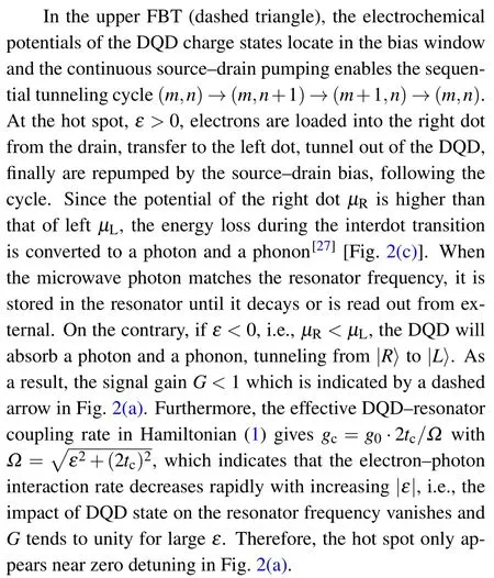
Fig.3. Distinguish the enhanced reflected signal between photon emission and frequency shift caused by the interdot transition. (a),(d)Stability diagram for VSD =0.5 mV where the hot spot is indicated by a triangle and the Coulomb blockade regime is indicated by a circle. (b), (e) Schematic diagrams illustrate the increased reflections that result from frequency shift and photon emission,respectively. (c), (f) Corresponding zoom-in spectra near the refection valley measured at the hot spot (triangle, dashed line) and Coulomb blockade(circle,solid line). The whole spectrum is shown in the inset.

Fig.4. Photon emission for source–drain bias VSD=0(a),0.2 mV(b),0.4 mV(c),−0.2 mV(d),and −0.4 mV(e).
5. Conclusion
We report the increased cavity response of a SQUID array resonator which results from the photon emission from a semiconductor DQD.Because of the high impedance of the SQUID array resonator,the large coupling strength between the DQD and resonator leads to effective energy transfer between electrons and microwave photons during the interdot tunneling when a DC voltage bias is consecutively applied across the DQD. By comparing the spectrum measured at the hot spot with the baseline in Coulomb blockade,we distinguish the signal gain caused by photon emission from frequency shift.
In our experiment, the microwave gain of the device is probed in reflection, employing a 1/4 wavelength SQUID array resonator.Compared with a half-wavelength transmissionline resonator,our resonator is designed with smaller footprint,which is advantageous to further on-chip integration with other devices. Furthermore, single-port microwave resonator can suppress the crosstalk between the input and output ports which improves the symmetry of the resonator spectrum.[34,35]Although we have detected the photon emission in the reflection spectrum, the large photon loss rate of the resonator as well as the fast decoherence rate of the DQD deteriorate the measurement. The observed gain at the hot spot is so weak that the photon emission rate is slower than the photon dissipation rate. Therefore, stable stimulated radiation is inaccessible in our voltage-biased DQD system. Provided a resonator and a DQD with better quality and larger coupling strength,we expect the gain will be large enough and coherent photon source will be realized in such hybrid cQED systems.
Acknowledgment
This work was partially carried out at the University of Science and Technology of China Center for Micro-and Nanoscale Research and Fabrication.
猜你喜欢
收藏与投资(2022年7期)2022-08-02
幼儿教育·父母孩子版(2022年4期)2022-05-08
艺术家(2020年9期)2020-11-03
作文周刊·小学三年级版(2020年20期)2020-09-02
科学导报·学术(2020年19期)2020-07-09
颂雅风·艺术月刊(2020年2期)2020-05-26
作文周刊·小学三年级版(2016年46期)2017-06-03
东方教育(2016年4期)2016-12-14
卷宗(2016年7期)2016-09-26
小天使·一年级语数英综合(2014年3期)2014-03-15
- Chinese Physics B的其它文章
- Speeding up generation of photon Fock state in a superconducting circuit via counterdiabatic driving∗
- Quantum plasmon enhanced nonlinear wave mixing in graphene nanoflakes∗
- Restricted Boltzmann machine: Recent advances and mean-field theory*
- Nodal superconducting gap in LiFeP revealed by NMR:Contrast with LiFeAs*
- Origin of itinerant ferromagnetism in two-dimensional Fe3GeTe2∗
- Intercalation of germanium oxide beneath large-area and high-quality epitaxial graphene on Ir(111)substrate∗