
Electric-field-induced in-plane effective 90°magnetization rotation in Co2FeAl/PMN-PT structure*
2021-05-24 02:27CaiZhou周偲DengyuZhu朱登玉FufuLiu刘福福CunfangFeng冯存芳MingfangZhang张铭芳LeiDing丁磊MingyaoXu许明耀andShengxiangWang汪胜祥
Chinese Physics B 2021年5期
关键词:丁磊
Cai Zhou(周偲), Dengyu Zhu(朱登玉), Fufu Liu(刘福福), Cunfang Feng(冯存芳), Mingfang Zhang(张铭芳),Lei Ding(丁磊), Mingyao Xu(许明耀),†, and Shengxiang Wang(汪胜祥),‡
1Hubei Province Engineering Research Center for Intelligent Micro-nano Medical Equipment and Key Technologies,Wuhan Textile University,Wuhan 430200,China
2Key Laboratory for Magnetism and Magnetic Materials,Ministry of Education,Lanzhou University,Lanzhou 730000,China
3Hubei Engineering and Technology Research Center for Functional Fiber Fabrication and Testing,Wuhan Textile University,Wuhan 430200,China
Keywords: electric field,90° magnetization rotation,Co2FeAl/PMN-PT structure
1. Introduction
For the development of next-generation electronic devices, it is highly desirable to find an efficient and precise way to control the high-frequency magnetic properties of soft magnetic materials.[1]Using the electric field provides a new route to control the magnetization direction/or magnetic anisotropy via magnetoelectric (ME) coupling in multiferroic materials.[2–8]It has the advantage of localization and low energy consumption compared with using magnetic fields or electric currents. Recently, the strong ME coupling has been achieved in the ferromagnetic/ferroelectric(FM/FE)multiferroic heterostructure through the piezostrain effect derived from FE substrate, then transferred to the ferromagnetic layer to control the magnetic parameters[9–11]and interfacial charge effect at the interface between the FM and FE layers.[12,13]However, the charge effect is most pronounced at charge screening lengths on the scale of a few angstroms,which requires stringent preparation conditions and impedes the application for magnetoresistive random access memory with high operation speed and low power consumption.[13]Therefore, the change of magnetization direction induced by the piezostrain is widely investigated in FM/FE structure. Gueye et al. reported that in Co2FeAl(CFA)thin film,the magnetic anisotropy in Co2FeAl (CFA) grown on Kapton could be mediated drastically by bending the sample, which reveals that CFA film with good magnetoelastic properties can be submitted to strains.[14]Nevertheless, the method of nonin-situ electric field-controlling magnetic anisotropy is a disadvantage for the development of many existing and emerging devices such as magnetoresistive random access memory. Recently, it is reported that the single-crystal ferroelectric material Pb(Mg1/3Nb2/3)O3-PbTiO3(PMN-PT) can control the magnetic anisotropy of the adjacent FM layer,which can lead to a strong ME coupling.[15–17]Therefore, in this work, the CFA films grown on the single crystal (011)Pb(Mg1/3Nb2/3)O3-PbTiO3substrate were prepared by magnetron sputtering. Thus, the in-plane effective 90°magnetization rotation induced by an electric field is demonstrated in CFA/PMN-PT structure.Under positive electric fields,the 90°magnetization rotation can be obtained by the measurement of the hysteresis loops under different electric fields,while remanent magnetization is nearly unchanged under negative electric fields. In addition, the behavior of the electric field dependence of effective magnetic field is consistent with that of remanent magnetization,which can be attributed to the piezostrain effect. Moreover,the piezostrain-mediated 90°magnetization rotation can be demonstrated by the result of the resonance field changing with the electric field in the measurement of ferromagnetic resonance.
2. Experiments
The CFA thin films were deposited by radio frequency magnetron sputtering on a single crystal (011) PMN-PT substrate. These sputtering parameters consisted of a base pressure of <5×10⁻⁵Pa,a power of 20 W,and working under a processing Ar pressure of 0.1 Pa. A 2-mm-thickness CFA target was used to deposit CFA films,which were sputtered with a thickness of 40 nm.The oblique sputtering angle was 10°.Pt layers,with thicknesses of 20 nm and 100 nm,were sputtered on the top and bottom sides of the CFA/PMN-PT heterostructure. Cu wires were then connected to the electrodes using adhesive tape. The schematic of the CFA/PMN-PT structure is shown in the inset of Fig.1(a). The sample with edges was cut along the x([100]direction)and y([01¯1]direction)of PMNPT, as shown in the inset of Fig. 1(b). The static magnetic properties of the CFA films were measured using a vibrating sample magnetometer (VSM, MicroSense EV9). Ferromagnetic resonance (FMR) measurements were performed using the JEOL, JES-FA 300 spectrometer (X-band at 8.969 GHz,power of 1 mW).The FMR absorption spectra were measured using a lock-in technique based on the sweeping of a static external magnetic field superimposed over the ac magnetic field.The biased voltage was applied to the CFA/PMNPT structure by an electrometer controlled using a Keithley 6517Bdc power supply.
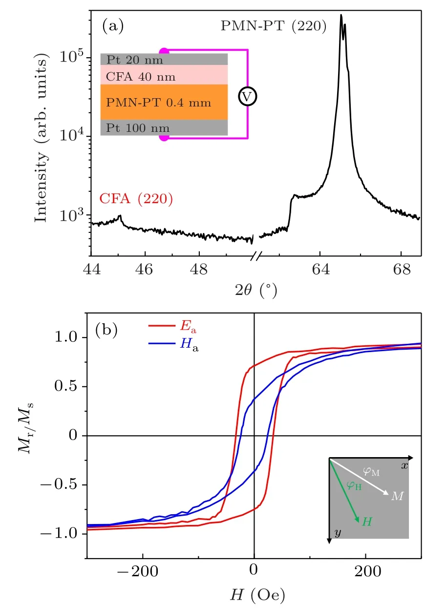
Fig. 1. (a) The XRD 2θ scanning patterns in the unpoled state for CFA/PMN-PT structure. The inset shows the schematic diagram of the CFA/PMN-PT structure. (b)The magnetic hysteresis loops along easy and hard axes in the unpoled state. The bottom view of field and magnetization directions.
3. Results and discussion
The out-of-plane θ–2θ XRD scan of the 40-nm CFA/PMN-PT structure in the unpoled state is shown in Fig. 1(a). The prominent (220) PMN-PT peak is recorded at 65.5°, which reveals the PMN-PT substrate with (011)-orientation.[18]The presence of the(220)CFA peak indicates that the CFA thin film contains the A2 phase.[19]For the sample of CFA/PMN-PT,the representative in-plane magnetic hysteresis loops of CFA thin film along the direction of easy and hard axes in the unpoled state are shown in Fig.1(b). The obvious in-plane uniaxial anisotropy can be obtained, which can be attributed to the oblique sputtering. In the unpoled state,the direction of the easy axis of the sample is the x direction, as shown in Fig. 1(b), which can be defined as 0°. The direction of the hard axis is along the y direction,regarding as 90°. The magnetic hysteresis loops along easy and hard axes,respectively,can be mediated by the electric field. For brevity,only data along the hard axis are plotted, which is shown in Fig. 2. The electric field from top to bottom is defined as positive. The maximum applied electric field is 15 kV/cm.The labels a,b,c,and d indicate sweeping electric field from a to d, as shown in Fig. 3(a). The sample is positively polarized initially. Under positive electric fields, the remanent magnetization ratio Mr/Mshas an obvious change, as shown in Fig.2(a). When the electric field increases from 0 kV/cm to 15 kV/cm,the magnetic hysteresis loop changes from a typical“hard-axis” curve to an “easy-axis” curve. However, Mr/Msseems to remain almost constant under negative electric fields,as shown in Fig.2(b). A similar result can be obtained along the easy axis, as shown in the inset of Fig. 3(b). These results reveal that the value of Mr/Mschanges under different electric fields, which can be attributed to the ME coupling in CFA/PMN-PT structure.
As shown in Fig. 3(a), the value of Mr/Msalong easy and hard axes, respectively, under different electric fields is directly obtained from the above magnetic hysteresis loops.For the value of Mr/Msalong the hard axis in blue color,under positive electric field, when the electric field is swept from 0 kV/cm to 7.5 kV/cm at stage a, Mr/Msis almost unchanged. In contrast, Mr/Msincreases sharply with the electric field increasing from 7.5 kV/cm to 15 kV/cm. Remarkably, Mr/Mschanges from 0.21 to 0.89, which indicates the effective 90°magnetization rotation. At stage b,Mr/Mshas a linear decrease when the electric field decrease from 15 kV/cm to 0 kV/cm.At stages c and d,Mr/Mshas little relative change under negative electric fields. A similar result can be obtained along the easy axis in red color. In addition,a positive or negative value of effective anisotropy field (Heff) under different electric fields is found, as shown in Fig.3(b). Heffcan be estimated by checking the cross point of the central line of the hard-axis loop with the counter extension of the magnetization saturation lines according to the S-W model. If the positive value of Heffis defined as the direction of the easy axis at 0°,the negative value of Heffrepresented the direction of the easy axis is at 90°. When the electric field is swept from 0 kV/cm to 7.5 kV/cm,the positive value of Heffchanges from 66 Oe to 102 Oe. However,the electric field increases from 7.5 kV/cm to 10 kV/cm,and the value of Heffchanges from 87 Oe(positive) to −53 Oe (negative), which reveals the effective 90°magnetization rotation. With the electric field increasing from 10 kV/cm to 15 kV/cm,the negative value of Heffincreases to−230 Oe,which suggests the direction of the easy axis is also at 90°. Moreover,the electric field changes from 15 kV/cm to 5 kV/cm,and the value of Heffis still negative. With the electric field decreasing to 2.5 kV/cm,a positive Heffof 8 Oe can be obtained. In addition,the value of Heffunder negative electric fields is all positive.The result may result from the competition between in-plane magnetic uniaxial anisotropy and the magnetoelastic anisotropy induced by piezostrain transferred from the PMN-PT substrate.

Fig.2. The magnetic hysteresis loops along the hard axis under different electric fields.
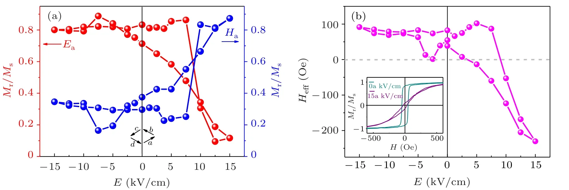
Fig.3. (a)The Mr/Ms–E curves along easy and hard axes,respectively. (b)The Heff–E curve. The inset shows magnetic hysteresis loops along the easy axis at 0 kV/cm and 15 kV/cm.
For an insight into the piezostrain effect in CFA/PMN-PT heterostructure,the S–E (strain–electric field)curve measured by the sample sticking on a strain gage (KFG-A-120-d17,KYOWA) is obtained as shown in Fig. 4(a), which exhibits the asymmetric butterfly-like behavior. Meanwhile, these results of in-plane rotating-angle VSM labeled with different color symbols under several representative electric fields are shown in Fig. 4. The sample was attached to a rotatable holder, and remanent magnetization Mrwas measured every 5°from 0°to 360°. Before obtaining each data point,a saturation field of 2000 Oe was first applied, then reduced to zero, to achieve a remanent magnetization state. For the electric field starting from 0 kV/cm to 7.5 kV/cm, the direction of the easy axis is along the [100]/[¯100], namely, 0°.With increasing the electric field to 10 kV/cm, the direction of the easy axis rotates to 90°, namely along [01¯1]/[0¯11],which demonstrates the appearance of in-plane effective 90°magnetization rotation. The direction of the easy axis remains stable until the electric field is reduced to 5 kV/cm.When the electric field continues to decrease to 2.5 kV/cm or 0 kV/cm, the direction of the easy axis turns back to 0°.When negative electric fields are applied, the direction of the easy axis is unchanged, even the electric field increasing to −15 kV/cm. The result is consistent with that of the Heff–E curve, as shown in Fig. 3(b). According to previous reports,[20–23]with increasing the electric field applied on the PMN-PT,the domain oriented along from〈111〉to〈100〉and the corresponding phase transition from rhombohedral to orthorhombic at room temperature are accompanied by a compressive strain along the x direction, which will result in an asymmetric S–E curve,leading to in-plane effective 90°magnetization rotation. It is worth noting that the 90°rotation of magnetization is absent when applying a negative electric field, which may be related to the asymmetrical S–E curve.The piezostrain effect for CFA/PMN-PT structure under a negative electric field is not enough to generate the 90°magnetization rotation. Moreover,the static magnetic property mediated by the electric field is consistent with that of the S–E curve,which can be attributed to the piezostrain effect.
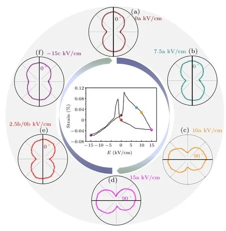
Fig.4. The S-E curve and the rotation history of the magnetic easy axis in the CFA film with a sequence of electric fields.
Generally,magnetic thin film applications are based on an analysis of the dynamic magnetic or magnetization processes,which are subjected to an effective magnetic anisotropy field Heff. Based on the VSM results given above, Heffhas been adjusted via the piezostrain effect. This result indicates the magnetic dynamics can also be mediated by the piezostrain effect. The schematic diagram of FMR measurement is shown in the inset of Fig.5(a). The electromagnet is used to provide a static external magnetic field. A cylindrical cavity resonator is set to put the sample at the center of the electromagnet. The microwave is generated by a waveguide connected with the cylindrical cavity resonator, which is normal to the sample.FMR spectra are measured in the unpoled state under different angles,as shown in Fig.5(a). The FMR spectrum can be fitted by an asymmetric Lorentzian function[24,25]

Here A is the integral coefficient. ΔH is the half-width at half-maximum of the linewidth. δ is the phase that mixes the real and imaginary parts of the dynamic susceptibility. H is the applied magnetic field. Hris the magnetic resonance field. These integration curves of the FMR spectra are fitted using Eq. (1), and related parameters are obtained. Based on the result of FMR spectra, resonance fields Hras a function of electric fields(Hr–E)along the easy axis and hard axis are obtained as shown in Fig.5(b). Under a positive electric field,with the electric field increasing from 0 kV/cm to 15 kV/cm,the value of Hralong the easy axis changes from 658 Oe to 862 Oe, while the value of Hralong the hard axis changes from 730 Oe to 385 Oe. The result of the dynamic magnetic property shown in Fig. 5 is similar to the tendency from the result of static magnetic property measured by VSM as shown in Figs. 2–4, which can be attributed to the piezostrain effect induced by the electric field.
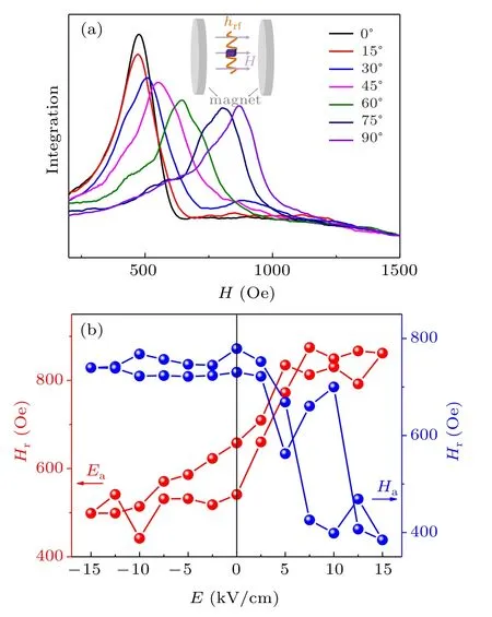
Fig.5. (a)The FMR spectra in the unpoled state under different in-plane rotation angles.The inset shows the schematic diagram of FMR measurement.(b)Hr–E curves along easy and hard axes,respectively.
4. Conclusion
In summary, the in-plane effective 90°magnetization rotation induced by the piezostrain effect is reported in Co2FeAl/PMN-PT structure. The remanent magnetization by hysteresis loops under different electric fields reveals magnetic property can be mediated by the electric field. Moreover, the 90°magnetization rotation can be observed under positive electric fields. The result is consistent with the electric field dependence of effective magnetic field,which can be attributed to the piezostrain effect in Co2FeAl/PMN-PT structure. In addition, through ferromagnetic resonance measurement,the result of resonance field changing with electric field demonstrates the piezostrain-mediated 90°magnetization rotation, which is promising for the design of the future multiferroic device.
猜你喜欢
计算机应用文摘·触控(2020年13期)2020-08-10
检察风云(2018年16期)2018-09-06
今古传奇·故事版(2017年20期)2017-11-22
校园英语·下旬(2017年6期)2017-07-14
小康(2017年10期)2017-05-02
中国经济周刊(2017年12期)2017-04-07
名人传记·财富人物(2016年12期)2017-01-19
名人传记·财富人物(2016年12期)2017-01-19
中国汽车界(2016年1期)2016-07-18
微型小说选刊(2014年2期)2014-06-24

- Chinese Physics B的其它文章
- Corrosion behavior of high-level waste container materials Ti and Ti–Pd alloy under long-term gamma irradiation in Beishan groundwater*
- Degradation of β-Ga2O3 Schottky barrier diode under swift heavy ion irradiation*
- Influence of temperature and alloying elements on the threshold displacement energies in concentrated Ni–Fe–Cr alloys*
- Cathodic shift of onset potential on TiO2 nanorod arrays with significantly enhanced visible light photoactivity via nitrogen/cobalt co-implantation*
- Review on ionization and quenching mechanisms of Trichel pulse*
- Thermally induced band hybridization in bilayer-bilayer MoS2/WS2 heterostructure∗