
Electrochemical Performance of Core-Sheath Dip-Coated Lignin Derived Carbon/Wet-Spun Graphene Electrodes for Fiber-Shaped Supercapacitors
2021-06-22 02:57HUWenxin胡文鑫LIUYanXIANGRuifang向睿芳JINGYuanyuan景媛媛XUQingli许庆丽ZHANGJuanHUXuefeng胡雪峰JINYanhong金艳红YANGXiaona杨晓娜CHENGYuLINJiaxian林佳娴ZHANGKunLUChunhong陆春红
关键词:艳红
HU Wenxin(胡文鑫), LIU Yan(刘 岩), XIANG Ruifang(向睿芳), JING Yuanyuan(景媛媛),XU Qingli(许庆丽), ZHANG Juan(张 娟), HU Xuefeng(胡雪峰), JIN Yanhong(金艳红), YANG Xiaona(杨晓娜), CHENG Yu(程 毓), LIN Jiaxian(林佳娴), ZHANG Kun(张 坤), LU Chunhong(陆春红)*
1 Key Laboratory of Textile Science & Technology, Ministry of Education, Donghua University, Shanghai 201620, China
2 College of Textiles, Donghua University, Shanghai 201620, China
Abstract: One-dimensional graphene fibers (GFs) possess excellent properties, including high electrical conductivity, good physical and chemical stability, high thermal conductivity, flexibility, etc. GFs are ideal electrode materials for fiber-shaped supercapacitors. However, due to the lack of an effective method to manufacture GFs with high specific capacitance, their low energy density hinders their practical application. Herein, we decorated wet-spun graphene oxide fibers (GOFs) by dip-coating them with graphene oxide (GO) solutions containing different contents of lignin to obtain a core-sheath lignin/GO composite fibers. After carbonization and activation, we successfully prepared lignin derived carbon/GF electrodes. The assembled fiber-shaped supercapacitors (FSSCs) exhibit a specific capacitance of 9.98 mF/cm2 and an energy density of 0.89 μW·h/cm2, about 6 times of those of pure GFs (1.57 mF/cm2 and 0.14 μW·h/cm2, respectively), long cycling life and cycling stability. This suggests that the introduction of lignin derived carbon into GFs can effectively increase the specific capacitance and the energy density of FSSCs.
Key words: wet-spinning; lignin derived carbon; graphene; specific capacitance; energy density
Introduction
In recent years, with the rapid development of electronics and energy storage devices, more attentions have been paid to smart textiles[1]. As for weavable and wearable energy storage devices, fiber-shaped supercapacitors (FSSCs) have excellent cycling life, ultra-high power density, rapid charge/discharge rate, good safety and reliability,etc.[2], and thus they have great potential in the application of smart textiles.
The electrode materials of FSSCs are usually pseudocapacitive and carbon-based materials. Although the pseudocapacitive materials (i.e., RuO2and MnO2) have a high capacity (i.e., the specific capacitance can reach 834 mF/cm2), they are seldom used in FSSCs due to their short cycling life, poor stability, low conductivity, low safety and high cost[3-5]. Compared with above-mentioned materials, carbon-based materials (i.e., graphene, carbon nanotubes and carbon black) have attracted much more attention due to their advantages such as high conductivity, good safety and long cycling life[6-9]. Among them, graphene has tunable structure, ultra-high theoretical specific surface area (SSA, 2 630 m2/g) and specific capacitance (550 F/g), high electrical conductivity (106S/m), flexibility and low cost, which make it a great potential electrode material in flexible wearable devices[10-12]. However, due to the strong π-π interaction between the graphene nanosheets, the restacking issue results in dramatic decrease of the SSA. Therefore, accessible SSA of solvated ions is greatly reduced, and storage capability and transportation efficiency of ions are also restrained in graphene-based supercapacitors. In order to address the issue of graphene nanosheet restacking, some efforts have been made. It is found that inserting spacers between graphene nanosheets is an effective way to increase SSA and further the electrochemical performance of the electrode material. For instance, Yuetal.[2]introduced single-walled carbon nanotubes (SWNTs) into graphene oxide fibers (GOFs) to obtain SWNTs/reduced graphene oxide (rGO) fibers through reductions. The study showed that the strong adhesion between SWNTs and rGO sheets effectively prevented the stacking of sheets, and the resultant fibers had a high SSA (396 m2/g) and an outstanding volumetric capacitance (305 F/cm3).
Lignin is the second largest renewable resource on the earth and is considered one of the most promising biopolymers. In recent years, lignin-based porous carbon nanocomposites have gradually drawn intense attention due to their excellent electrochemical properties[13-14]. It is worth noting that lignin can be mixed with GO in any ratio in alkaline solution due to the presence of oxygen-containing functional groups in the chemical structures of both lignin and GO. Hydrogen bonds can be easily formed between lignin and GO, and they can effectively prevent restacking of GO nanosheets during the carbonization process[15]. Tranetal.[16]fabricated a porous carbon film based on lignin and GO, which demonstrated an SSA of 1 744 m2/g and an excellent specific capacitance of 162 F/g. Liuetal.[17]successfully prepared graphene dispersion by direct exfoliation of graphene in aqueous medium with alkaline lignin as a surfactant. Although the above-mentioned examples suggest that lignin is an effective spacer in graphene nanosheets, little work focuses on the fabrication of lignin derived carbon/graphene-based fiber electrodes. Since lignin has an amorphous structure and a low molecular weight, the introduction of lignin into GOFs will diminish the original crystalline structure of fibers and result in fibers with low strength, which are extremely difficult to collect and further characterize. Therefore, it is important to construct a fiber structure that can effectively combine the advantages of lignin and GO to further enhance the electrochemical performance of fiber electrodes.
In this work, we reported an all-carbon, core-sheath structured graphene-based fiber with lignin derived carbon/graphene as a sheath active material for charge diffusion/storage and GF as a core mechanical support so that the electrode is strong enough for further characterization and assembly of FSSCs. The graphene-based fiber electrodes were fabricated by a simple, scalable and cost-effective wet-spinning/dip-coating method followed by high-temperature carbonization/activation.
1 Experiments
1.1 Materials
Graphite oxide (SE2430W) was purchased from Changzhou Sixth Element Material Technology Co., Ltd., China. Lignin was purchased from Sigma-Aldrich, USA. Poly(vinyl alcohol) (PVA, low viscosity), ammonia, potassium hydroxide (KOH), acetic acid and sulfuric acid (H2SO4) with a weight percentage of 98% were bought from Sinopharm Chemical Reagent Co., Ltd., China. Deionized (DI) water was made with a Master-Q15 machine (a resistivity of about 18.3 MΩ·cm).
1.2 Preparation of GOFs and graphene fibers (GFs)
Graphite oxide (3.5 g) was dissolved in DI water (400 mL). A small amount of ammonia was added dropwise into graphite oxide aqueous solution. The mixture was magnetically stirred at room temperature until there was no obvious graphite oxide clump observed, and then was sonicated for 1 h to obtain a homogenous GO dispersion. GO dispersion was diluted with DI water until it was translucent. It was subsequently centrifuged at 3 000 r/min to remove the unexfoliated graphite. The supernatant solution was filtered and then centrifuged at 8 000 r/min to remove small size GO sheets. The solution at the bottom layer was concentrated to 20 mg/mL as a spinning dope for wet-spun GOFs.
GOFs were prepared by wet-spinning as shown in Fig. 1 and the process can be described as follows. GO dispersion (20 mg/mL) was injected into the acetic acid coagulation bath through a spinneret with an inner diameter of 300 μm. The as-spun fibers were collected continuously by a winder and then air dried. GFs were obtained by high-temperature treatment of GOFs in the center of a tubular furnace (YGS-1700). In order to fully remove the oxygen in the quartz tube and further prevent GOFs from oxidation and decomposition in the heating process, the tubular furnace was repeatedly filled with high-purity nitrogen and vacuumed for 5 times before heat treatment. In detail, GOFs were first heated up to 800 ℃ at a heating rate of 2.5 ℃/min in nitrogen atmosphere. After they were heated at this temperature for 3 h, they were taken out of the nitrogen filled furnace for natural cooling in air.
1.3 Preparation of lignin derived carbon/graphene sheath/graphene fibers core composite fibers (CG@GFs)
As shown in Fig. 1, CG@GFs were prepared by the dip-coating method which could be described as follows. Different loadings of lignin were added into the GO solution (the mass ratios of lignin to GO were 3%, 5% and 10%, respectively) and magnetically stirred at room temperature for 2 h to yield homogenous solution mixtures. The prepared GOFs in the last section were immersed in lignin/GO (LGO) solution mixtures for coating. The obtained composite fibers were labeled as 3% LGO@GOF, 5% LGO@GOF, 10% LGO@GOF, respectively. Subsequently, the prepared LGO@GOFs were carbonized in the furnace with the temperature first being increased from room temperature to 800 ℃ at a heating rate of 2.5 ℃/min and remained at 800 ℃ for 3 h in nitrogen atmosphere. Then heat-treated LGO@GOFs were immersed in 1 mol/L KOH solution for 12 h and dried in an oven. The dried fibers were heated up to 800 ℃ at a heating rate of 5.0 ℃/min and continuously heated at 800 ℃ for 2 h for activation. Finally, the activated fibers were washed by DI water and dried in air to obtain CG@GFs. The sheath layer originally contained 3%, 5% and 10% lignin. After carbonization and activation treatment, lignin was converted into carbon, and GO was transformed into graphene in the sheath. In the core, GOFs were accordingly converted into GFs after heat treatment and activation. Therefore, composite fibers are expressed as 3% CG@GF, 5% CG@GF and 10% CG@GF, respectively.

Fig. 1 Preparation of core-sheath graphene-based composite fibers and assembly process of fibrous supercapacitors
1.4 Assembly of FSSCs
PVA (1 g) was dissolved in DI water (10 mL) and magnetically stirred at 90 ℃ until complete dissolution. After PVA solution was cooled down to room temperature, H2SO4(0.98 g) was added dropwise into PVA solution to form the PVA/H2SO4gel electrolyte. The assembly of FSSCs could be described as follows. Two fiber electrodes were placed parallel to each other on a flexible polyester (PET) film substrate, and then were immersed in the PVA/H2SO4gel electrolyte. The ends of each fiber were glued onto a polished copper foil by silver paste, respectively. The assembled supercapacitors were dried at room temperature until the electrolyte was completely solidified.
1.5 Structure characterization of fibers
The surface morphology and the cross-sectional morphology of GFs and CG@GFs were characterized by a scanning electron microscope (SEM, SU8010, Japan) at an accelerating voltage of 5 kV. The chemical structure of GOFs and GFs were characterized by a Fourier transform infrared (FTIR) spectroscope (NEXUS-670, USA).
1.6 Electrochemical performance measurements of fiber electrodes
The electrochemical performance measurements of fiber electrodes include cyclic voltammetry (CV), galvanostatic charge/discharge (GCD) and electrochemical impedance spectroscopy (EIS, from 0.01 Hz to 100 kHz). These tests were performed by an electrochemical workstation (CHI660E, China) in a two-electrode configuration. The capacitanceCcelland the energy densityEsingle, Aof supercapacitors were calculated according to the equations reported in Ref. [9].
(1)
whereu1andu2are the lowest voltage and the highest voltage in the CV curve, respectively;IandUrepresent the instantaneous current and instantaneous voltage, respectively;uand ΔUare the scan rates in the CV curve and potential window, respectively. The areal specific capacitanceCAand volumetric specific capacitanceCVof a single fiber can be calculated by
CA=2Ccell/Asingle,
(2)
CV=2Ccell/Vsingle,
(3)
whereAsingleandVsingleare the cross-sectional area and the volume of a single fiber at a certain length, respectively.
Asingle=πDL,
(4)
Vsingle=πD2L/4,
(5)
whereDandLare the diameter of a single fiber and the length of the fiber electrode immersed in the electrolyte, respectively. The areal energy densityEsingle, Aand volumetric energy densityEsingle, Vof the fiber electrode are calculated as
Esingle, A=CAV2/7 200,
(6)
Esingle, V=CVV2/7 200,
(7)
whereVis the potential window.
2 Results and Discussion
The experimental process is shown in Fig. 1. In detail, GOFs were first prepared by a simple, scalable and low-cost wet-spinning method, and then a layer of LGO solution mixture with different lignin concentrations was dip-coated onto the surface of GOFs. Subsequently, the core-sheath structured LGO/GOFs were carbonized and activated at high temperature to yield core-sheath structured carbon-based composite fibers (CG@GFs). Finally, CG@GFs were immersed in the PVA/H2SO4gel electrolyte and assembled into FSSCs for further structural and electrochemical performance characterization.
2.1 Structure evolution mechanism of GOFs
To better understand the fiber formation process, the structure evolution mechanism of GOFs by wet-spinning is shown in Fig. 2. In detail, GOFs are formed and solidified in the acetic acid coagulation bath, where solvent exchange occurs with water diffusing out from the GO solution jet into the coagulation bath[shown in Fig. 2(a)]. Meanwhile, acetic acid can diffuse into the solution jet to ionize with water and release protons (H+), thereby inhibiting the dissociation of acidic groups (—COOH) on the GO nanosheets. With less water, the GO nanosheets quickly solidify under the influence of hydrogen bonds and van der Waals forces between nanosheets in the coagulation bath to form as-spun GO fibers[shown in Fig. 2(b)]. Water and the volatile acetic acid are further removed from as-spun GO fibers after being dried by an infrared (IR) lamp. Thus GO nanosheets instantly collapse to yield solid GO fibers with a dense structure[shown in Fig. 2(c)].
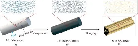
Fig. 2 Schematic illustration of structure evolution mechanism of GOFs by wet-spinning: (a) solvent exchange; (b) as-spun GO fibers formation; (c) solid GO fibers formation
2.2 Structure of GFs and CG@GFs

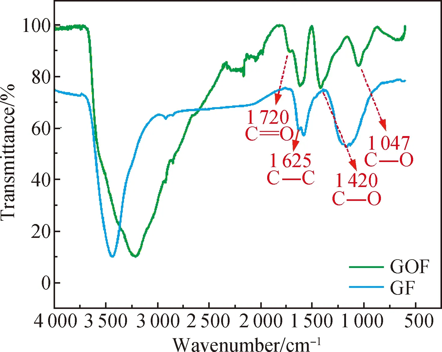
Fig. 3 FTIR spectra of GOFs and GFs
SEM images of different fibers are shown in Fig. 4. It is indicated that the pure GF has a clean and wrinkled surface with a diameter of about 45 μm[shown in Fig. 4(a)]. The wrinkled surface favors the formation of mesopores, which may contribute to the electrochemical performance of the fiber electrode. It is also obvious that the wrinkled graphene nanosheets are highly aligned and oriented along the fiber axis probably due to the stretching force during the spinning process. In addition, as shown in Fig. 4(c), the pure GF is composed of dense graphene sheets, which originate from the restacking of graphene sheets. In Fig. 4(d), dip-coated fibers show smooth surface, indicating that the LGO solution mixtures are successfully coated onto the surface of GOFs. However, the cracks on the surface indicate the uneven coating. In Figs. 4(g) and (h), there are many particles of lignin derived carbon and graphene flakes on the fiber surface. No obvious boundary of core-sheath in the cross-sections of CG@GFs[shown in Figs. 4(f) and (i)] is observed. These evidences also indicate the uneven coating. Moreover, after KOH activation of CG@GFs[shown in Fig. 4(h)], no obvious porous structure is observed on the fiber surface under high magnification. The pores in the cross-sections of GFs and CG@GFs are probably formed when the fiber structure collapses in solvent evaporation and fiber drying processes, as described in the previous section.
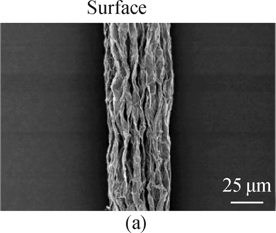
Fig. 4 SEM images: (a)-(c) GF; (d)-(f) unactivated 5% CG@GF; (g)-(i) 5% CG@GF
2.3 Electrochemical performance of GFs and CG@GFs
In order to verify that the introduction of lignin derived carbon can effectively enhance the specific capacitance of GFs, electrochemical performance from the CV, GCD and EIS curves of the assembled FSSCs in the two-electrode cell system will be discussed in this section.
The CV curves of carbon-based FSSCs at a scan rate of 100 mV/s are shown in Fig. 5(a). The CV curves of GF FSSCs are approximately rectangular, indicating typical electrical double-layer capacitor energy storage mechanism. Compared with these of pure GF, the CV curves of CG@GF FSSCs are enlarged, indicating their better charge storage capacity as fibrous electrode materials. This is probably due to that lignin derived carbon materials are rich in oxygen-containing groups that can increase the wettability of the electrode material and promote the adsorption of electrolyte ions onto the electrode surface[18]. Therefore, the addition of lignin derived carbon favors the enhancement of the capacitive performance of GFs. Notably, the CV curve of 5% CG@GF FSSCs shows a reduction peak when the voltage is about 0.4 V. This is due to that abundant oxygen-containing groups in lignin can provide additional pseudocapacitance. Its oxidation peak is possibly related to the polarization phenomenon, which often leads to the shift of the peak position towards a higher voltage. The possible redox reactions are shown in Eqs. (8)-(10)[19]. It is worth noting that redox peaks are not observed in the CV curves of 3% CG@GF FSSCs and 10% CG@GF FSSCs, which further verifies that the dip-coating of LGO solution onto GOFs is not uniform.
(8)
carboxylic—COOH←→—COO+H++e-
(9)
(10)
Figure 5(b) shows GCD curves of all fiber electrodes at the current density of 0.01 mA/cm2. It can be seen that all the curves present approximately symmetrical isosceles triangles, indicating that the fiber electrodes have good charge/discharge capabilities. The potential drops of GF, 3% CG@GF, 5% CG@GF and 10% CG@GF curves are 8.2, 14.0, 9.3 and 11.2 mV, respectively. This indicates that the charge storage capacity of FSSCs is reduced after the addition of lignin derived carbon. It should be noted that a platform appears when the voltage is 0.4 V during charge/discharge of 5% CG@GF, which is attributed to the reduction peak in the CV curve. In comparison with the discharge time of the pure GF electrode (43 s), the discharge time of all fiber electrodes increases after adding lignin derived carbon. The discharge times of 3% CG@GF, 5% CG@GF, and 10% CG@GF are 229, 244 and 338 s, respectively. And 10% CG@GF has the longest discharge time, suggesting that it has the best electrochemical performance.
Figure 5(c) shows the relationship between areal specific capacitances and scan rates based on the CV curves. Table 1 summarizes the calculated specific capacitances related to the electrochemical performance of fiber electrodes and FSSCs based on CV curves at a scan rate of 5 mV/s. It can be seen from Table 1 that the areal specific capacitance of the pure GF at a scan rate of 5 mV/s is 1.57 mF/cm2. The specific capacitance values of CG@GFs are higher than those of the pure GF. Particularly, 10% CG@GF has the highest areal specific capacitance (9.98 mF/cm2), which is about 6 times of that of the pure GF, indicating that the addition of lignin derived carbon effectively enhances the areal specific capacitance of GFs. In Fig. 5(c), all FSSCs show a decreased tendency in areal specific capacitance when the scan rate increases from 5 mV/s to 200 mV/s. This is due to that a faster scan rate reduces the transfer efficiency of electrons within the active material since the response time is greatly shortened. The capacitance retention rates of GF, 3% CG@GF, 5% CG@GF, and 10% CG@GF are 26%, 8%, 11%, and 12%, respectively, implying that the capacitance retention rate decreases with the introduction of lignin derived carbon.

Table 1 CA, CV, Esingle, A and Esingle, V of fiber electrodes based on CV curves at a scan rate of 5 mV/s
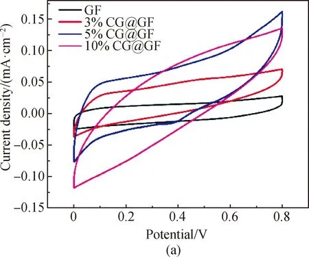
Fig. 5 Electrochemical performance of GF, 3% CG@GF, 5% CG@GF and 10% CG@GF measured in two-electrode cells with PVA/H2SO4 gel electrolyte: (a) CV curves at a scan rate of 100 mV/s; (b) GCD curves recorded at a current density of 0.01 mA/cm2; (c) areal specific capacitances based on CV curve versus measured scan rates; (d) Nyquist plots of the FSSCs from GF, 3% CG@GF, 5% CG@GF, and 10% CG@GF
Figure 5(d) shows the Nyquist plots of GF and CG@GF electrodes. Nyquist plots typically consist of an out-of-shaped semicircle of a half ellipse in high and intermediate frequency ranges with imaginary part ofZ(Z″) inYaxis and a straight line inclined at a constant angle to the real axis (Z′) in the lower frequency range at the initial state. The ion diffusion process is reflected by the low frequency region[20].
The equivalent series resistance (ESR) of GF, 3% CG@GF, 5% CG@GF and 10% CG@GF are 450.8, 1 116.0, 807.0 and 737.0 Ω, respectively. The higher ESR of CG@GFs is attributed to the increase of the amorphous area of graphene-based fibers with the introduction of the carbonized lignin. This is related to a decrease in crystallinity, and further a decrease in the electrical conductivity (shown in Fig. 6) and an increase in the potential drop[shown in Fig. 5(b)]. In addition, the slope of the pure GF electrode in the low frequency region is greater than that of the CG@GF electrodes. Therefore, GF has a higher ion diffusion efficiency. Together with the low ESR aforementioned, GF exhibits the highest capacitance retention rate.

Fig. 6 Electrical conductivity of GFs and CG@GFs

Fig. 7 Cyling stability of FSSCs:(a) capacitance retention rate of FSSCs based on 10% CG@GF after 2 000 cycles; (b) GCD curve of 10% CG@GF FSSCs in 1 996th-2 000th cycles in a voltage window of 0-0.8 V
In addition toCA,CVvalues,Esingle, AandEsingle, Vbased on CV curves at a scan rate of 5 mV/s are also shown in Table 1. It can be summarized that after the introduction of lignin derived carbon into GF, the areal energy density and the volumetric energy density evidently increase from 0.14 μW·h/cm2and 0.12 mW·h/cm3to 0.89 μW·h/cm2and 0.70 mW·h/cm3, respectively.
Figure 7 shows the cycling stability of 10% CG@GF FSSCs through continuous measurement of GCD capacitance performance at a current density of 0.1 mA/cm2. The capacitance of 10% CG@GF FSSCs remains 93% of the initial capacitance after 2 000 charge/discharge cycles, showing excellent cycling stability. The GCD curve of 10% CG@GF FSSCs shows a symmetrical triangle, indicating that it can maintain high stability even after a long cycle.
3 Conclusions
We have successfully prepared lignin derived carbon/graphene composite fibers by dip-coating LGO solution mixtures onto wet-spun GOF surface. The specific capacitance and energy density of the assembled 10% CG@GF FSSCs are about 6 times of those of the pure GF (1.57 mF/cm2to 9.98 mF/cm2and 0.14 μW·h/cm2to 0.89 μW·h/cm2, respectively), and the assembled 10% CG@GF FSSCs exhibit long cycling life and cycling stability (after 2 000 charge/discharge cycles) with a capacitance retention rate of 93%. These results strongly suggest that lignin derived carbon can increase the electrochemical performance of GFs. However, structural defects such as an uneven fiber surface caused by nonuniform dip-coating may hinder further enhancement of electrochemical performance. Therefore, it is of great importance to develop an effective method that fabricates core-sheath structure lignin derived carbon/GFs with a uniform surface and better electrochemical performance.
猜你喜欢
安徽农业大学学报(2022年2期)2022-11-09
快乐作文(1.2年级)(2022年3期)2022-04-14
美与时代·美术学刊(2021年10期)2021-11-25
大众文艺(2021年20期)2021-11-10
农业工程(2021年1期)2021-04-02
快乐作文·低年级(2016年4期)2016-04-25
母子健康(2015年8期)2015-12-13
文学与艺术(2010年1期)2010-04-22
中学生英语·中考指导版(2008年7期)2008-12-19
 Journal of Donghua University(English Edition)2021年2期
- Journal of Donghua University(English Edition)的其它文章
- Preparation and Properties of Polyurethane/Nickel Nanofiber with Core-Shell Structure Using Coaxial Electrospinning Method
- Trajectory Optimization and Motion Simulation of a Flexible Polishing Industrial Robot for Watchcases
- Effect of Supported Bearing Clearance on Load-Sharing Characteristics of a Double-Row Planetary Gear System
- Meta-Analysis on the associations between Prenatal Perfluoroalkyl Substances Exposure and Adverse Birth Outcomes
- Numerical Simulation of Space Fractional Order Schnakenberg Model
- Symmetry Classification of Partial Differential Equations Based on Wu’s Method