
Research on the method of dual-frequency microwave diagnosis of plasma for solving phase integer ambiguity
2021-09-10 09:26XiaopingLI李小平ChengweiZHAO赵成伟YanmingLIU刘彦明JiahuiZHANG张珈珲DonglinLIU刘东林ChaoSUN孙超andWeiminBAO包为民
Plasma Science and Technology 2021年9期
关键词:东林
Xiaoping LI (李小平),Chengwei ZHAO (赵成伟),Yanming LIU(刘彦明),*,Jiahui ZHANG(张珈珲),Donglin LIU(刘东林),Chao SUN (孙超) and Weimin BAO (包为民)
1 School of Aerospace Science and Technology,Xidian University,Xi’an 710071,People’s Republic of China
2 Key Laboratory of Information and Structure Efficiency in Extreme Environment,The Ministry of Education of China,Xi’an 710071,People’s Republic of China
Abstract In this work,microwaves and terahertz waves have performed a dual-frequency combined diagnosis in high-temperature,large-scale plasma.According to the attenuation and phase shift of electromagnetic waves in the plasma,the electron density and collision frequency of the plasma can be inversely calculated.However,when the plasma size is large and the electron density is high,the phase shift of the electromagnetic wave is large (multiple times 2π period).Due to the limitations of the test equipment,the true phase shift is difficult to test accurately or to recover reality.That is,there is a problem of phase integer ambiguity.In order to obtain a phase shift of less than 180°,a higher electromagnetic wave frequency(terahertz wave with 890 GHz)is used for diagnosis.However,the attenuation of the terahertz wave diagnosis is too small(less than 0.1 dB),only the electron density can be obtained,and the collision frequency cannot be accurately obtained.Therefore,a combined diagnosis was carried out by combining two frequencies (microwave with 36 GHz,terahertz wave with 890 GHz) to obtain electron density and collision frequency.The diagnosis result shows that the electron density is in the range of(0.65–1.5)×1019 m−3,the collision frequency is in the range of 0.65–2 GHz,and the diagnostic accuracy is about 60%.
Keywords: microwave diagnosis,phase integer ambiguity,combined diagnosis,large-scale plasma
1.Introduction
When a spacecraft re-enters the atmosphere,it will fly at extremely high speeds.Due to the strong friction with the air,the air is ionized and plasma is generated around the spacecraft.There are a large number of charged particles in the plasma,which will affect the communication between the spacecraft and the outside,and even cause a‘black out’effect in severe cases[1–5].The propagation performance of communication electromagnetic waves is determined by the electron density and collision frequency of the plasma [6].Therefore,the diagnosis of plasma electron density and collision frequency is of great significance.Commonly used plasma diagnostic methods are probe diagnostics [7],laser interference diagnostics [8,9],microwave diagnostics [10–14],and spectroscopy [15].
Langmuir probe is an early and commonly used diagnostic method in plasma research.The Langmuir probe measures the volt-ampere (V-A) characteristic curve of the plasma using a conductive needle tip,so that the relevant parameters of the plasma can be deduced,such as electron temperature,electron density,energy distribution,and space potential [16].B Liet alinvestigated the use of absorption probes for the diagnosis of plasma[17].Because the probe is in direct touch with the plasma,the probe will burn out when the plasma temperature is high (about 3000 K).Therefore,in the research of high-temperature plasma,probe diagnosis is not suitable and a non-contact diagnosis method is generally used.
Laser interference diagnosis is a commonly used nontouch diagnostic method [18].This method assumes the plasma as a medium,and the refractive index of the laser in the plasma is related to the electron density of the plasma.The electron density can be obtained by the refractive index of the laser in the plasma.Due to the high frequency of the laser,laser interference diagnosis has advantages at high electron densities.However,when the electron density is low,the laser interference diagnosis has a large error,and the collision frequency cannot be diagnosed.
Microwave diagnosis is a commonly used non-touch diagnostic method,which also assumes plasma as the medium.The microwave diagnosis method is simple and reliable,with small plasma disturbance and low cost,so it is widely used.Microwave diagnosis can be divided into reflection diagnosis and transmission diagnosis[11–14].In addition,the electron density at different positions can be estimated based on the reflection phase,so that the electron density can be diagnosed in layers.Microwave transmission diagnosis can estimate the electron density and collision frequency based on the transmission attenuation and phase shift of electromagnetic waves in the plasma.However,when the size of the plasma is thick,the transmission phase shift of the transmitted electromagnetic wave may be a multiple of the period (2π),which makes it difficult to recover the true phase shift.In summary,each diagnostic method has its own strengths and weaknesses,so the various methods need to be compared and used for reference.
In this work,inductively coupled plasmas (ICP) have been diagnosed and measured.Plasma has the characteristics of long duration,high temperature,high electron density,and good uniformity,and the microwave transmission method is adopted for diagnosis.Due to the large plasma size and high electron density,the phase shift of electromagnetic waves after transmission exceeds multiple periods (360°),so the diagnosis of electron density is difficult.Due to the large plasma size and high electron density,there is a problem of phase integer ambiguity after the electromagnetic wave passes through the plasma,which makes microwave diagnosis difficult.Therefore,the actual phase shift can be calculated by referring to the electron density of the laser diagnosis,thereby obtaining accurate electron density and collision frequency.Finally,the accuracy of microwave diagnosis is analyzed from four aspects,and a comprehensive diagnosis accuracy is given.
The paper is arranged as follows.In section 2,the theory of transmission diagnosis is given.In section 3,the plasma generation and microwave diagnosis system are described.Microwave diagnostic test results and analysis are given in section 4.In section 5,the conclusion is given.
2.Theoretical analysis of plasma microwave transmission diagnosis
In classical theory,plasma is considered a special conductive dispersive medium.Electrodynamics equations are used to describe the laws of motion of charged particles in a plasma,and the dielectric constant and conductivity of the plasma can be derived.Combined with Maxwell’s equations,the attenuation and phase shift of electromagnetic waves in the plasma can be obtained by using the propagation law of plane electromagnetic waves in the lossy medium.Conversely,the electron density and collision frequency of the plasma can be derived by the attenuation and phase shift of the electromagnetic wave in the plasma.
It is well known that the attenuation constant α and phase shift constant β of electromagnetic wave propagation in plasma are as follows:

wherecis the velocity of light in the vacuum,ω is the angular frequency of the incident electromagnetic wave,νeis the plasma collision frequency,ωpis the characteristic angular frequency of the plasma,and the expression of ωpis as follows:

After the electromagnetic wave passes through the plasma of thicknessd,the attenuationAttand the phase shift φ are respectively:

where φpis the phase in which the electromagnetic wave propagates in the plasma,φ0is the phase in which the electromagnetic wave propagates in free space,β is the phase constant of the electromagnetic wave in the plasma,and β0is the phase constant of the electromagnetic wave in the free space.It can be seen from equations (4) and (5) that the attenuation and phase shift of electromagnetic waves are related to electron densityne,collision frequency νe,plasma thicknessd,and incident electromagnetic wave angular frequency ω.
Conversely,the electron density and collision frequency can also be calculated by the attenuation and phase shift of electromagnetic waves in the plasma.According to the formulas (1)–(5),the expressions of electron density and collision frequency are as follows:
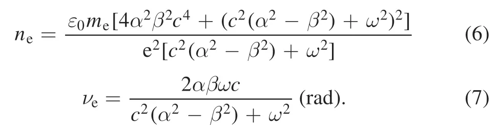
When the collision frequency νeis relatively low,the characteristic angular frequency ωpof the plasma and the angular frequency ω of the incident electromagnetic wave are equivalent,that is,ωp≫νe,ω≫νe,ωp~ω.Formulas (4)and (5) can be simplified as follows:

wheredis the transmitted plasma thickness and λ is the wavelength of the incident electromagnetic wave in free space.It can be seen from equations (8) and (9) that the angular frequency ω of the incident electromagnetic wave must be greater than the characteristic angular frequency ωpof the plasma,otherwise equation (9) is meaningless.From a physical point of view,when the frequency of the incident electromagnetic wave is close to or less than the characteristic frequency of the plasma,the attenuation is very large,and the electromagnetic wave cannot be transmitted.Therefore,in the microwave transmission diagnosis of plasma,the frequency of transmitted electromagnetic waves must be higher than the corresponding plasma characteristic frequency.
Taking the plasma thickness of 150 mm and the collision frequency of 2 GHz as an example,the attenuation and phase shift of electromagnetic waves at different electron densities are analyzed.The frequencies of the incident electromagnetic waves are 26.5 GHz,32 GHz,and 40 GHz,and the corresponding characteristic frequencies are 0.871×10¹⁹m−3,1.27×1019m−3,1.99×1019m−3,respectively.The specific attenuation and phase shift curves are shown in figure 1.
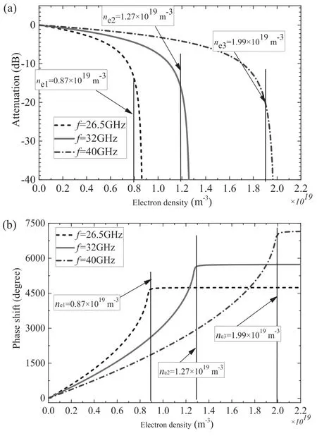
Figure 1.(a) Attenuation and (b) phase shift of electromagnetic waves at different electron densities.
It can be seen from figure 1(a)that when the frequency of the incident electromagnetic wave is close to the characteristic frequency of the plasma,the attenuation increases sharply,which indicates that the microwave transmission diagnosis can only diagnose plasmas with a characteristic frequency lower than the frequency of the incident electromagnetic wave.As shown in figure 1(b),as the electron density gradually increases,the phase shift of the electromagnetic wave also gradually increases.When the frequency of the incident electromagnetic wave is close to the characteristic frequency,the phase shift basically does not change.The maximum phase shift is in good agreement with formula (9),which is related to the plasma thickness and the wavelength of the incident electromagnetic wave.For frequencies of 26.5 GHz,32 GHz,and 40 GHz,the maximum phase shifts are 4770°,5760°,and 7200°,respectively.
In order to avoid large phase shifts in transmission diagnosis,the frequency of incident electromagnetic waves needs to be increased.When the electromagnetic wave frequency is much higher than the plasma characteristic frequency ωpand the collision frequency νe,the phase shift of the electromagnetic wave in the plasma will be relatively small.Therefore,the electron density of the plasma can be obtained only by the amount of phase shift.Simplifying formula (9),and taking Taylor series broadening to the formula under the radical sign,and combining formula (3),the relationship between electron density and phase shift can be obtained:
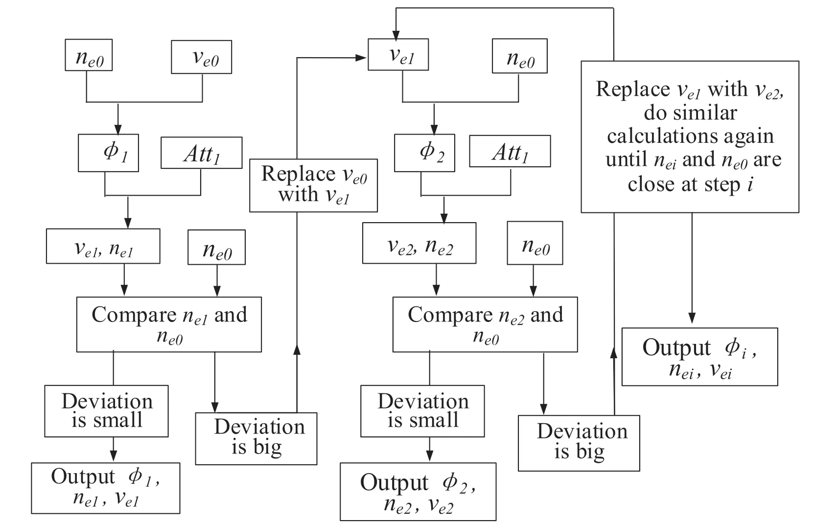
Figure 2.Flow diagram of phase shiftφ,electron density ne and collision frequency νe calculation for microwave transmission diagnosis.
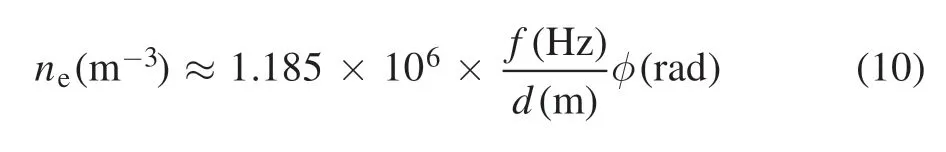
wherefis the frequency of the incident electromagnetic wave,dis the thickness of the transmitted plasma,and φ is the phase shift after the plasma is transmitted.
Through formula (10),only the electron density can be obtained,but the collision frequency cannot be obtained.In order to obtain the collision frequency,two electromagnetic waves of different frequencies can be combined,assuming that the frequencies aref1andf2,wheref2>f1.The attenuation and phase shift off1andf2transmitted through the plasma areAtt1,φ01,Att2and φ02,respectively.In addition,φ01is relatively large (greater than 1000°),andAtt2is very small (<0.1 dB).First,the electron densityne0can be obtained by φ02.SinceAtt2is relatively small,it can be considered thatne0is closer to the real state.Combiningne0and the assumedve0,the phase shift φ1corresponding to the frequencyf1can be obtained.The calculated phase shift φ1and the measured attenuationAtt1are substituted into equations(1)and(5)to obtain the electron densityne1and the collision frequency νe1.Comparingne1andne0,if the difference is large,replace νe0with νe1and repeat the calculation.Until the stepi,neiandne0are very close,so that φi,nei,and νeiare closest to the real.A clearer calculation flow diagram is shown in figure 2.
Take the plasma electron densityne=1.0×10¹⁹m−3,the collision frequencyve=2.0 GHz,and the plasma thickness of 150 mm as an example.For electromagnetic wave frequencyf1=36 GHz,f2=890 GHz,the corresponding attenuation and phase shift are:Att1=−27.4 dB,φ01=2481°,Att2=−0.028 dB and φ02=81.5°.Therefore,the method shown in figure 2 can be used for combined diagnosis.
3.Introduction of plasma generation and microwave diagnosis system
The plasma source is generated by inductively coupled plasma (ICP) with a supply power between 50 kW and 500 kW.Figure 3(a) shows a system block diagram of a plasma-generating apparatus.After the plasma is generated,it is mixed by the mixing section,so that the plasma electron density is more uniform.The generated plasma was sprayed toward the inside of the microwave chamber by a circular spout with a diameter of 150 mm,and thus the diameter of the plasma jet was also about 150 mm.The temperature at the center of the plasma jet is about 3000 K,so each test apparatus in the vacuum chamber must be resistant to high temperatures or add a water-cooling device.The inner wall of the vacuum chamber is equipped with microwave-absorbing materials,so that a series of electromagnetic wave experiments can be carried out.

Figure 3.Plasma microwave transmission diagnostic system.(a)Top view (xoz-plane),(b) front view (xoy-plane).
Due to the high temperature of the plasma (about 3000 K),the probe will burn out when diagnosed with a conventional Langmuir probe.Therefore,the diagnosis of plasma requires a non-touch diagnostic method,and microwave and laser diagnosis are two commonly used diagnostic methods.In this article,the two frequencies for plasma diagnosis are a microwave frequencyf1=36 GHz and a laser frequencyf2=890 GHz.Because the 890 GHz electromagnetic wave belongs to the terahertz frequency band,laser interference diagnosis is also called terahertz wave diagnosis.In plasma diagnosis,microwave diagnosis and terahertz wave diagnosis are performed simultaneously.The path of microwave diagnosis and the path of terahertz wave diagnosis are 50 mm apart,as shown in figure 3(a).Because the plasma positions of microwave diagnosis and terahertz diagnosis are different,the plasma parameters are also different.Analyzed by other diagnostic methods,there is a difference of about 20%in the electron density at a distance of 50 mm.Therefore,for the joint diagnosis of different positions,the error caused by different positions is about 20%.In order to reduce the position error,it is better to have the same diagnosis position,or use non-simultaneous measurement methods to obtain the same position diagnosis result.The equipment for terahertz wave diagnosis is placed outside the vacuum chamber; see[18]for details.This article focuses on microwave diagnostic equipment and test data.
The plasma microwave transmission diagnosis system can be divided into three parts,which are composed of a vector network analyzer (VNA),coaxial cable and a hightemperature point-focusing antenna,as shown in figure 3.The VNA was selected as the Anristu MS4647B,which operates at a frequency bandwidth of 10 MHz to 70 GHz,and is placed outside the vacuum chamber.Since the center temperature of the plasma jet is about 3000 K,the coaxial cable and the transmitting and receiving antenna must be able to withstand high temperatures.A coaxial cable is wrapped with hightemperature-resistant material to ensure stable operation at high temperatures.The microwave signal in the coaxial cable is transmitted to the VNA outside the vacuum chamber via the 2.92 mm-kk adapter on the sealing flange.
The focusing lens antenna is specifically designed for the measurement system [12].The lens is made of high-temperature-resistant quartz material and can work stably for a long time at temperatures below 1373 K,the lens antenna is mounted on both sides of the plasma jet,and the distanceL1of the transmitting and receiving antenna is 1000 mm (the temperature here is lower than 800 K).The diameterD1of the plasma spout is 150 mm,and thus the diameter of the plasma jet is also about 150 mm.However,in the diagnosis of specific plasma,it is necessary to take instant photographs of the plasma,and determine the size of the plasma according to the gray scale of the plasma.The lens antenna operates at a frequency of 26.5–40 GHz.When a metal cylinder with a diameter of 150 mm is placed in the middle of the transmitting and receiving antenna,the diffraction through the lens antenna is smaller than 50 dB,so the diffraction of the electromagnetic wave is completely negligible.In addition,the heightH1between the lens antenna and the bottom surface is 2000 mm,so the influence of reflection on the ground is also small.
4.Diagnosis test and analysis
4.1.Transmission attenuation of microwave in plasma
According to the introduction of the plasma microwave diagnosis method in section 2,microwave transmission diagnosis can be performed on large-size high-temperature plasma.The plasma is generated by inductive coupling.Since argon gas is more easily excited[19],the plasma is generated by the coupling of argon gas and then the coupling of air,so that there are many kinds of plasma states.Various states of the plasma are determined by different input quantities.The input quantities include the coupling input power,the type of coupling gas,and the input quantity of the coupling gas.
According to section 2 of this article,the electron density of the plasma can be obtained by measuring the attenuation and phase shift of the incident electromagnetic wave after transmitting the plasma.When the incident electromagnetic wave frequency is 36 GHz,the attenuation of different plasma states is shown in figure 4.In figure 4,the plasma is first coupled with argon and then coupled with air.The input power of the coupled argon is 80 kW,and the input amount of argon is unchanged,and the duration is about 20 s.Then the input gas is switched to air without changing the input amount.
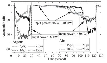
Figure 4.Microwave transmission attenuation in different states at frequency of 36 GHz.The former period is the attenuation at different input amounts of argon,and the latter is the attenuation at different input amounts of air.
When the input gas is air,the input air volume does not change,and the power gradually increased from 80 kW to 450 kW,and lasted for about 20 s at 450 kW,and then the power was turned off.In the above plasma coupling sequence,the gas input amount was adjusted,and four sets of plasma coupling tests were performed.In addition,when the input gas is air and the input power is lower than 400 kW,the electromagnetic wave attenuation is small and the plasma density is relatively low.According to formulas (4)–(8),if a lower-frequency (less than 20 GHz) electromagnetic wave is used for transmission experiments,the attenuation will be more obvious and the transmission diagnosis accuracy will be more accurate.Therefore,this article focuses on the transmission measurement of argon with an input power of 80 kW and air with an input power of 450 kW.At the same input power,the transmission attenuation is also different with the amount of input gas.As shown in figure 4,when the input gas is argon,the attenuation gradually increases as the input volume increases.However,when the input volume is 10 grams per second (g s−1),the attenuation no longer increases as the air input increases.It is shown that when the air input is 10 g s−1,the plasma electron density is maximum.Similarly,when the input gas is air,the input volume is 15 g s−1,the attenuation is the most obvious,and the electron density is also the largest.Therefore,different states of plasma can be given by different input conditions.
In order to more vividly illustrate the plasma in different states,figure 5 shows the plasma paragraphs in different states.When the input gas is argon,the generated plasma is very obvious and the diameter is large.When the coupling gas is air and the input power is relatively small,the plasma luminescence is relatively weak.When the input power is 450 kW,the brightness of the plasma is relatively bright,which means that as the input power increases,the electron density gradually increases.Therefore,the transmission attenuation of the electromagnetic wave is gradually increasing,which also verifies the change curve of the electromagnetic wave attenuation in figure 4.
4.2.Combined diagnosis of microwave and terahertz wave
When the input gas is air and the input power is between 80–400 kW,the attenuation of electromagnetic waves at a frequency of 36 GHz is small,so the electron density and collision frequency in this state are not calculated in detail.Therefore,figure 6(a) only shows the measured data of the attenuation of the electromagnetic wave with the input gas being argon and power of 80 kW,and the input gas being air and power of 450 kW.However,after the electromagnetic wave is transmitted through the plasma,the phase shift has great errors and confusion.This is because the plasma is thick(about 150 mm in diameter),and the phase shift caused by the plasma may exceed multiple 360°,as shown in figure 1(b).The range of the equipment recorded by the test is±180°,so it is difficult to reproduce the true phase shift.When the phase shift at a similar time is reversed (jumping from −180° to+180°,or vice versa),the phase shift is artificially recovered,as shown in figure 6(b).However,the phase shift recovered by the above artificial method has a large deviation,as shown in figure 6(c),and there is a large deviation between the diagnosed electron density and the terahertz wave diagnosis result.
The path of microwave diagnosis and the path of terahertz wave diagnosis are 50 mm apart,as shown in figure 3(a).Therefore,it can be considered that the electron densities of terahertz wave diagnosis and microwave diagnosis are basically close.The terahertz frequency used is 890 GHz,and the phase shift produced by the formula(12)is about 122°.Therefore,there is no large phase shift,so the diagnosis accuracy is closer to reality.Figure 6(c) shows the electron density of two methods of microwave transmission diagnosis and terahertz wave diagnosis.From the two diagnosis results,there is a large error in the diagnosis of microwave transmission due to the inaccurate phase shift after transmission.
However,terahertz wave diagnostics can calculate the electron density,but not the collision frequency.In order to recover the phase shift in microwave transmission,it can be obtained by the dual frequency point diagnosis method introduced in section 2,as shown in figure 2.The phase shift,electron density and collision frequency obtained by the above methods are shown in figure 7.It can be seen from figure 7(b) that the electron density obtained from the attenuation and phase shift of the microwave is very close to the electron density of the terahertz wave diagnosis.Therefore,according to the above calculation and analysis,the plasma can be divided into three periods.(1) When the input gas is argon,the input amount is 6 g s−1,and the input power is 80 kW; the electron density is about 0.65×10¹⁹m−3and the collision frequency is about 2.2 GHz.(2) When the input gas is air,the input amount is 15 g s−1,and the input power is less than 400 kW; the plasma electron density is much less than 1.0×10¹⁹m−3.Due to the low electron density,the attenuation and phase shift of microwave transmission are small,and the error of the diagnosed collision frequency is relatively large.Therefore,when the electron density is low,a more accurate electron density and collision frequency can be obtained by using a lower-frequency electromagnetic wave for transmission diagnosis.(3) When the input power is 450 kW,the electron density is about 1.5×10¹⁹m−3and the collision frequency is 0.65 GHz.
The electron density and collision frequency calculated above are analyzed and explained as follows:
(a) The plasma is assumed to be uniform in space,but it is actually non-uniform.
(b) The plasma is assumed to be basically invariant with time when the input state is stable.Even though the plasma changes over time,the average electron density is analyzed.

Figure 5.Photographs of the color morphology of the plasma in different states.(a)The input of argon is 6 g s−1 and input power is 80 kW,(b) the input of air is 15 g s−1 and input power are 450 kW.
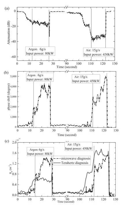
Figure 6.(a) Attenuation,(b) phase shift in different states at frequency of 36 GHz.(c) Electron density was obtained by microwave transmission diagnostics (with phase shift errors) and terahertz wave diagnostics;some states(input power between 80 kW and 400 kW) are hidden.
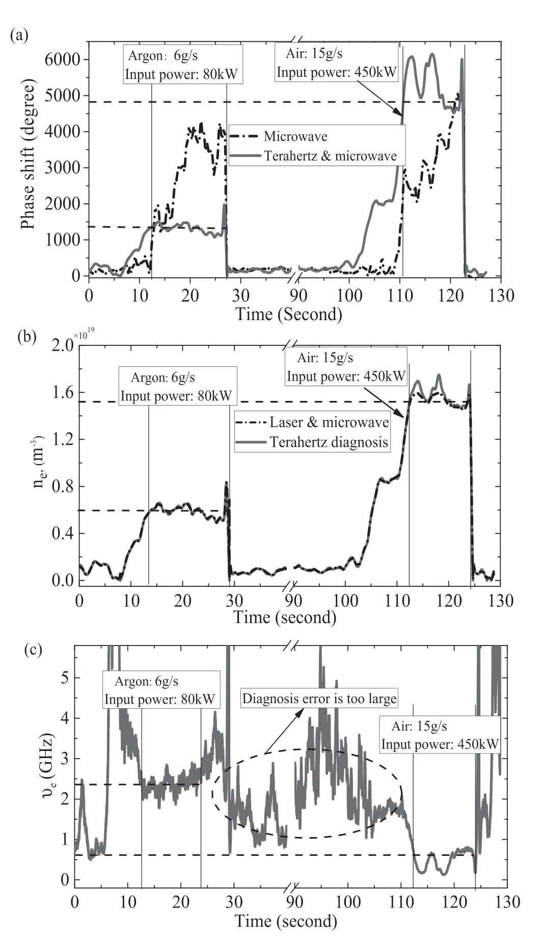
Figure 7.(a) Phase shift φ,(b) electron density ne,and (c) collision frequency ve obtained by plasma electron density and electromagnetic wave attenuation.
(c) The actual plasma is cylindrical,so the thickness of the plasma is assumed to be the diameter of the cylinder.
(d) The calculated electron density and collision frequency are both equivalent electron density and equivalent collision frequency,which is the average value of the electromagnetic wave on the transmission path.
4.3.Analysis of diagnostic accuracy
When the microwave method is used to diagnose plasma,the diagnostic accuracy of plasma must be given.The diagnosis accuracy is to compare the diagnosis result with the plasma truth value,but the plasma truth value is not known.For inductively coupled plasma (ICP),the diagnosis results need to be considered from the following aspects: equipment and operation errors,the statistical error of plasma fluctuation,formula error,measurement method and system error,etc.
First,the equipment uses a VNA.The minimum amplitude and phase of the VNA are 0.1 dB and 0.1°respectively,so it has high measurement accuracy.The test transmission cable is a high-performance low-loss phase-stable cable,which is fixed during the measurement,and through the measurement,without any operation,stable test for 5 min,the range of transmission amplitude and phase change is±0.1 dB,±1°,which shows that the cable is very stable.The transmitting and receiving antennas adopt a high-temperatureresistant focusing antenna,and the antenna focal spot size is less than 20 mm@36 GHz; see reference [13].The plasma range is about 150 mm,so the influence of microwave diffraction is negligible.Before the test,the equipment is calibrated,and the equipment is in a stable state during the test,so the error of equipment and operating can be ignored.
Second,there are fluctuations in the plasma itself,which is also a characteristic of inductively coupled plasma.In figure 7(b),the electron density of state 1(Ar 6 g s−1,80 kW)fluctuates at ±23%,and the electron density of state 2 (air 15 g s−1,450 kW)fluctuates at 11.6%.The diagnosis result is the average of the fluctuation value.
Third,the diagnosis formula is derived from certain theoretical assumptions and mathematical deductions.Therefore,the accuracy of the diagnostic formula should be relatively high and can be ignored.For the dual-frequency point-combined diagnosis,the calculation process is shown in figure 2.Through iterative calculation,the calculation result gradually approaches the terahertz diagnosis result,and the error in this part is estimated to be <2%.
Fourth,the measurement method and system error are a comprehensive result,and the diagnosis of known media can be analyzed by the same method.In order to give the diagnostic accuracy,we use the same diagnostic method to diagnose the dielectric constant of the common dielectric material PTFE,and compare it with the standard PTFE parameter,so as to give the accuracy of the diagnostic system and the diagnostic method; according to the transmission characteristics of microwave to the medium,the dielectric constant of the medium is obtained through attenuation and phase shift.The specific formula is as follows:
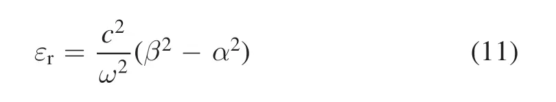
where εris the relative dielectric constant of the medium,which mainly affects the propagation phase of the electromagnetic wave.
It is known that the dielectric constant of PTFE is between 2.0 and 2.2,and the same erection method is used to diagnose the dielectric constant of PTFE.Here we use three frequency points 26 GHz,32 GHz,and 38 GHz to diagnose the dielectric constant.The dielectric constants diagnosed at the three frequencies are 2.028,2.061,and 2.171.According to the dielectric constant of 2.1,the diagnostic accuracy of the three frequencies is greater than 96%.Therefore,it can be considered that the measurement method and system error is less than 4%.
Based on the above analysis,there is a distance of 50 mm between microwave and terahertz at the diagnosis position,and there is a 20% combined diagnosis error.The plasma is generated by the ICP,and there is a fluctuation of about±11.6% to ±23%.The diagnosis result is an average value over a short period of time (about 5 s).Therefore,combined with the analysis of the diagnostic equipment,formula analysis,etc,the comprehensive diagnostic error is about 60%;that is,the diagnostic accuracy is about an order of magnitude.In order to improve the diagnostic accuracy,the following aspects need to be improved:reduce the fluctuation of the plasma,reduce the position deviation of the two diagnostic methods,and improve the accuracy of the equipment.
5.Conclusion
In this paper,microwave and terahertz waves have performed a dual-frequency combined diagnosis in high-temperature,large-scale plasma.Because the phase shift of electromagnetic waves in the plasma may exceed multiple periods(360°),it is difficult to test the phase shift accurately and recover it.Based on the electron density of the terahertz wave diagnostic system,the precise phase shift and collision frequency of electromagnetic waves in the plasma are given.Through error analysis,the overall diagnosis accuracy is about 60%.In the future,the accuracy of diagnosis can be improved by reducing the fluctuation of the plasma and reducing the positions of the two diagnoses.
Acknowledgments
This work was supported in part by National Natural Science Foundation of China (Nos.61627901,61601353,61801343 and 61901321).
ORCID iDs
猜你喜欢
小学生优秀作文(高年级)(2022年4期)2022-04-25
江苏教育(2021年12期)2021-08-02
求学·理科版(2021年5期)2021-04-08
新阅读(2019年3期)2019-09-10
岁月(2019年4期)2019-04-28
西部论丛(2019年8期)2019-03-08
东方剑(2018年11期)2018-02-20
博览群书(2016年6期)2016-07-25
醒狮国学(2014年8期)2015-01-30
醒狮国学(2014年8期)2015-01-30
 Plasma Science and Technology2021年9期
- Plasma Science and Technology的其它文章
- Recent results of fusion triple product on EAST tokamak
- Suppression and mitigation of inter-ELM high-frequency Alfvén-like mode by resonant magnetic perturbation in EAST
- Simulations of NBI fast ion loss in the presence of toroidal field ripple on EAST
- Reconstructions of velocity distributions from fast-ion D-alpha (FIDA) measurements on EAST
- Tomography of emissivity for Doppler coherence imaging spectroscopy diagnostic in HL-2A
- Comparison of natural grassy ELM behavior in favorable/unfavorable Bt in EAST