
Design and multistability analysis of five-value memristor-based chaotic system with hidden attractors∗
2021-10-28 07:07LiLianHuang黄丽莲ShuaiLiu刘帅JianHongXiang项建弘andLinYuWang王霖郁
Chinese Physics B 2021年10期
Li-Lian Huang(黄丽莲) Shuai Liu(刘帅) Jian-Hong Xiang(项建弘) and Lin-Yu Wang(王霖郁)
1College of Information and Communication Engineering,Harbin Engineering University,Harbin 150001,China
2MIIT Key Laboratory of Advanced Marine Communication and Information Technology,Harbin 150001,China
Keywords: five-valued memristor,chaotic system,hidden attractor,multistability
1. Introduction
In 1971, professor Chua first proposed the concept of memristor and confirmed that it is the fourth basic circuit element used to describe the relationship between charge and magnetic flux except resistance, capacitance, and inductance.[1]In 1976, professor Chua further extended the concept of ideal memristor to the dynamic system of generalized memristor,namely memristor system.[2]However,due to the incomplete preparation technology at that time, it is difficult to make the real memristor, resulting in the following quite a long time, the related research on memristor has not been well developed. Until 2008, HP Lab confirmed the scientific prediction of 37 years ago to the world, and realized the physical model of the world’s first memristor using titanium dioxide material,[3]which confirmed its physical realizability,and promoted the development process of world electronic science and technology. At the same time,many mathematical models with memristor characteristics have been reported, such as piecewise linear memristor,[1,4]quadratic nonlinear memristor,[5,6]and cubic nonlinear memristor.[7,8]These memristor models have simple structure and obvious memristor characteristics, which are suitable for the application and research of memristor in various oscillation circuits.
Memristor has potential application value in many fields,such as logic circuit,[9]neural network,[10]nonvolatile memristor memory,[11]and information security,[12]because of its unique nonlinear characteristics and easy to combine with oscillation circuits to produce complex and changeable chaotic signals. The design of new chaotic circuit based on memristor are also the current research hotspot. In Ref.[4],Itoh and Chua designed a Chua’s chaotic circuit based on memristor by replacing the nonlinear resistance in Chua’s circuit with broken line memristor, whose dynamic behavior becomes more complex. In Ref. [13], Mutthuswamy designed a new piecewise linear memristor model and replaced the nonlinear resistance in Chua’s chaotic circuit to obtain a memristor-based chaotic system, which can produce double scroll attractors.In Ref. [14], Xi proposed piecewise linear, quadratic nonlinear, cubic nonlinear and quartic nonlinear memristors-based fractional-order Lorenz systems, and intermittent chaos was observed.In Ref.[15],Bao proposed an inductance-free memristor circuit which is linearly coupled by an active band-pass filter, a shunt memristor, and a capacitor filter. Its stability is closely related to the initial value of memristor, and it shows extreme multistability.
With the further study of memristor theory and memristor chaotic circuit,more and more scholars pay attention to explore new memristor chaotic systems with special dynamic behavior. In Ref.[16],Wang proposed a memristor chaotic system with infinite equilibrium points,which can produce a huge and complex basin of attraction. In Ref.[17],Zhou proposed a new three-dimensional(3D)chaotic system with hidden dynamic behavior,which can generate a variety of different types of hidden coexisting attractors, and implemented the system using DSP platform. In Ref. [18], Zhang introduced a multiscroll hyperchaotic system with hidden attractors based on jerk system, which has infinite number of equilibrium points and the number of scroll is controllable. In Ref. [19], Deng proposed a hidden attractor chaotic system with a stable equilibrium point, which can produce four-scroll attractors, singlescroll attractors,and attractors coexisting with the period and quasi period. In Ref. [20], Yan proposed a memristor-based fractional-order hyperchaotic system,the coexisting hidden attractors are observed with different initial conditions and the hidden dynamic characteristics of the system are verified by using the SampEn complexity. In Ref.[21],a new fractionalorder chaotic system is proposed based on the Adomian decomposition method, three characteristic initial offset boosting behaviors were observed by varying the initial conditions of the system and the digital circuit was implemented on a DSP platform.
Inspired by Refs.[22,23],this paper proposes a five-value memristor model and design a new chaotic system based on the model. However,different from Ref.[22],the five-valued memristor has more segmented characteristics,and the memductance function becomes more complex.Compared with the memristor chaotic system introduced in the reference,the system in this paper has more abundant dynamic characteristics,such as multistabilities and super-multistabilities. The chaotic system introduced in Ref.[23]has rich dynamic behaviors,but it is not extended to hidden attractors and transient chaos,and the number of scroll of attractor is at most 2. The system introduced in this paper not only produces 1-scroll and 2-scroll,but also generates 4-scroll attractors.
The paper is organized as follows. In Section 2, a fluxcontrolled five-value piecewise linear memristor model is proposed,and the hysteresis loop characteristics of the model are simulated. In Section 3,based on the classical Liu–Chen system, a new chaotic system with hidden attractors is designed by using the five-valued memristor, and the dynamic behavior of the new system is analyzed in detail. In Section 4, the circuit of the memristor chaotic system is designed and simulated,and the results are in good agreement with the numerical analysis. Finally,the work of this paper is summarized in the last section.
2. Flux-controlled five-valued memristor
Different from the classical binary memristor, the memristor model proposed in this section has five different memristor states and is extremely sensitive to the change of excitation voltage frequency,which mathematical model is expressed as

whereqis charges,ϕis magnetic flux. The derivative of Eq.(1)is shown below:

where dq/dt=i(t), dϕ/dt=v(t),sgn(·)is a symbolic function,the memductance functionW(ϕ)of flux-controlled fivevalued memristor is shown as
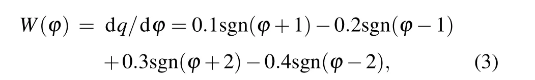
after sorting out, the relationship between memductance and magnetic flux is obtained as follows:

The characteristic curve of the five-valued memristor described by Eq. (1) onϕ–qis shown in Fig. 1(a), which is composed of five straight lines with different slopes. Equation (2) describes the volt–ampere relationship of the fivevalued memristor. The memductance relationship described by Eq. (3) and equation (4) is shown in Fig. 1(b). Obviously,the memristor is controlled by its internal state variable flux, and the corresponding memductance value in each state is equal to the slope of the straight line segment in theϕ–qcurve.
According to the general definition of memristor,[24,25]the flux-controlled five-valued memristor model can be represented as
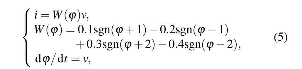
wherevis input voltage,iis output current.
Consider a single port network with only one five-valued memristor described by Eq. (5). A sinusoidal voltage source is applied to the network port as the excitation,and the mathematical expression is as follows:

whereVmis amplitude andfis frequency.
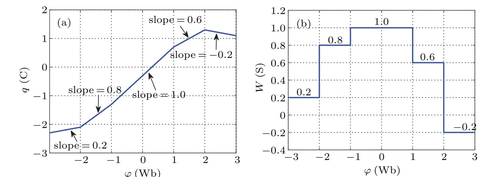
Fig. 1. Characteristic curve and memductance relationship curve of fvie-valued memristor. (a) The ϕ–q characteristic curve, (b) the memductance relationship curve.
Set amplitudeVm= 2 V, internal initial condition of memristorϕ0=−3 Wb,and when the frequencyfis 0.2 Hz,0.5 Hz, and 1 Hz, thev–icharacteristic curve is shown in Fig.2. Obviously,when a sinusoidal excitation is applied,the characteristic curve of the memristor on thev–iplane is a hysteresis loop which is compressed at the origin. Meanwhile,with the increase of frequency, the sidelobe area of hysteresis loop decreases monotonously and shrinks to a single value function, which is consistent with the essential characteristic of the memristor.[26]
Letf=0.1 Hz,ϕ0=−3 Wb, when the value ofVmis 1 V, 5 V, and 10 V, thev–icharacteristic curve is shown in Fig. 3. LetVm=2 V,f=0.1 Hz, when the value ofϕ0is−2 Wb, 0 Wb, and 1.5 Wb, thev–icharacteristic curve is shown in Fig. 4. From the simulation results, it can be seen that under the sinusoidal voltage excitation, regardless of the excitation amplitude,frequency,and the internal initial conditions of the memristor, it can show the characteristics of the hysteresis loop at the origin in thev–iplane,which is the main feature of the memristor different from other non-memristor elements.
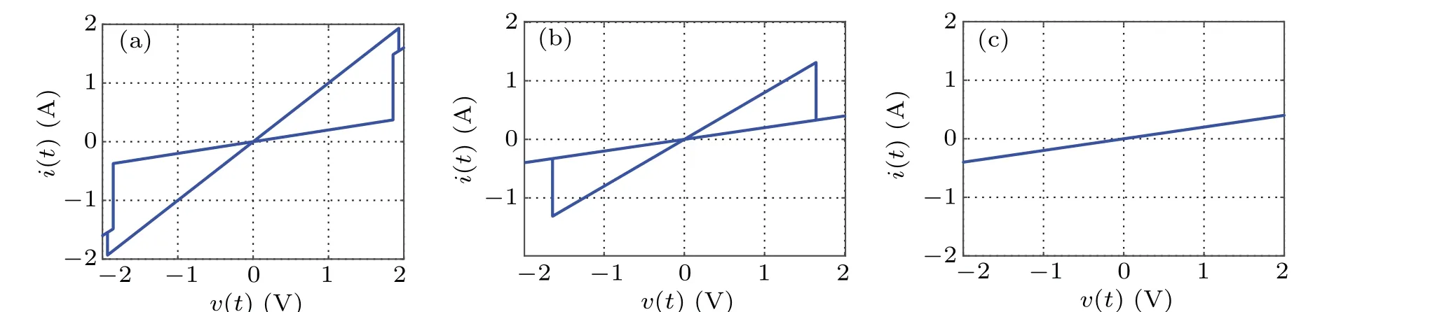
Fig.2. The v–i curve of five-valued memristor at different frequencies: (a) f =0.2 Hz,(b) f =0.5 Hz,(c) f =1.0 Hz
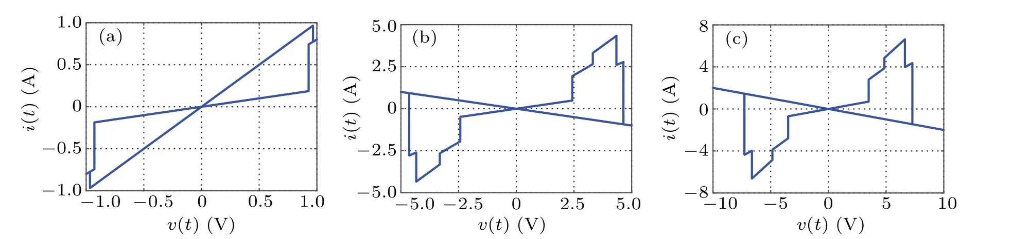
Fig.3. The v–i curve of five-valued memristor at different amplitudes: (a)Vm=1 V,(b)Vm=5 V,(c)Vm=10 V.
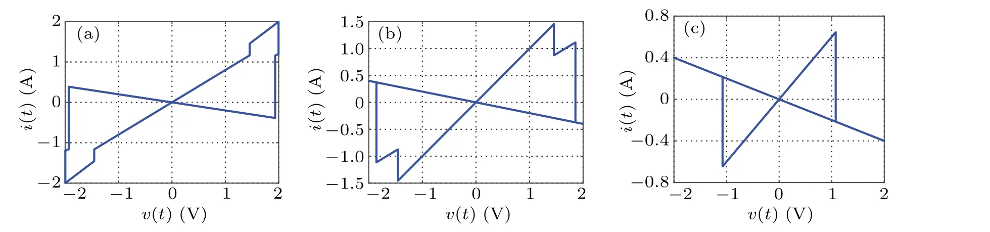
Fig.4.The v–i curve of five-valued memristor at different internal initial conditions of the memristor:(a)ϕ0=−2 Wb,(b)ϕ0=0 Wb,(c)ϕ0=1.5 Wb.
3. Five-valued memristor-based chaotic system
In 2004,Liu–Chen proposed a pseudo four-wing chaotic system, which can produce a pair of two-scroll coexisting attractors with close position arrangement,and have good symmetry and rich dynamic behavior.[27,28]In this paper, a new memristor-based 4D chaotic system is constructed by introducing a five-valued memristor,which mathematical model is expressed as
whereεis an arbitrary constant. Therefore the system has infinitely many equilibrium points. The jacobian matrix is obtained by linearizing system(7)at the equilibrium pointO,as shown in the following formula:
According to Eq.(10), the characteristic equation can be further obtained as

By solving the above equation, the characteristic root of the system is shown below:
Set system parametersa=5,b=10,c=2,d=0.1,e=1,f=0.1 andk=0.1,it is found that no matter what the value ofεis,the eigenvalueλ4is always greater than 0,so the system is unstable at the equilibrium point setO.
Whenk/=0,by solving Eq.(8),it is easy to getx=y=0,dz=kby taking it into the third equation we get−ck/d=0,but the parameterscandkare all non-zero constants, obviously this is a contradiction Therefore, in the case ofk/=0,there is no solution to the equilibrium equation,so no equilibrium point exists in the system. According to the definition of hidden attractors,[29]no matter what the value of parameterkis,the system has hidden attractor generation.
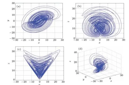
Fig.5. Hidden attractor phase diagram of five-valued memristor based chaotic system. (a)The two-dimensional(2D)plot in plane x–y plane,(b)the 2D plot in x–z plane,(c)the 2D plot in y–z plane,(d)The 3D plot in x–y–z space.
Let the initial values of the state variables be(1,1,1,10).In the limited simulation time, a hidden double scroll attractor is obtained,and its phase diagram is shown in Fig.5. The Lyapunov exponentLE1= 1.40,LE2=−0.003948,LE3=−0.06238,LE4=−8.339, and Lyapunov dimensionDL=3.1609 are calculated. Obviously, the system (7) has a positive Lyapunov exponent and fractional dimension, which is consistent with the Lyapunov exponent and dimension characteristics of the chaotic system,and chaotic behavior will occur.
3.1. Dissipative analysis
The dissipativity of system(7)can be represented by
whena,b,csatisfya−b−c<0,the system is dissipative.
Bring in the parametera−b−c=−7,so the system(7)satisfies the dissipative condition. Therefore, the phase space of the system converges exponentially and the volume elementV0shrinks toV0e−(b+c−a)tatttime. If the timetapproaches infinity,the trajectories of the system will be compressed into a set whose volume is close to zero,namely the trajectories are infinitely close to the attractor region.The existence of chaotic attractors is proved.
3.2. Initial value sensitivity
Let the initial value of the system(7)be(1,1,1,10)without external interference and(100000001, 1,1,10)with external interference. Solve the system equations in the above two cases and the simulation results are shown in Fig.6. The blue part in the figure shows no interference and the red part shows interference. Obviously, although the added disturbance is very weak, the time-domain waveform and phase diagram of the system have undergone very obvious changes. Especially in Fig. 6(a), it can be clearly seen that the time series without interference and with interference almost coincide at the beginning,but with the evolution of time,the two trajectories are separated quickly,accompanied by strong aperiodicity and pseudorandomness,and finally form two completely different trajectories.
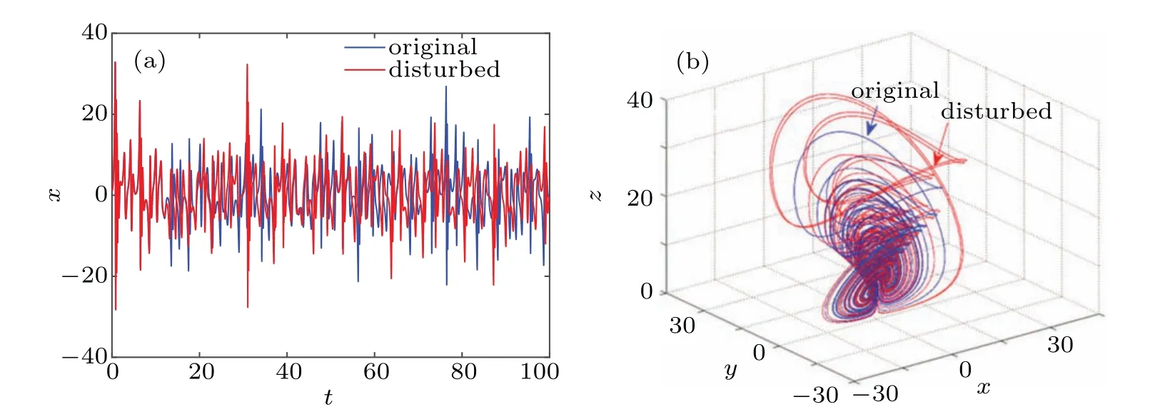
Fig.6. Sensitivity analysis of initial value. (a)The t–x sequence diagram,(b)the 3D plot in x–y–z space.
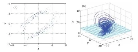
Fig.7. Poincare mapping with z=10 section. (a)The 2D plot in plane x–y plane,(b)the 3D spatial structure.
3.3. Poincare mapping
Poincare mapping is a common method to analyze the dynamic system. The specific method is to select a cross section ofn −1 dimension in then-dimensional phase space of the system, and analyze the motion law of the system by observing the intersection distribution of the evolution trajectory and the cross section of the system. When there is a continuous curve or a dense sheet point set,the system is chaotic. Select the cross section asz=10, and the corresponding Poincare mapping is shown in Fig. 7(a). In order to have a more intuitive feeling about the acquisition of Poincare mapping,figure 7(b) shows the 3D spatial structure of Poincare mapping.Obviously,there are a lot of dense points on the cross section,which is consistent with the essential characteristics of chaos,and further verifies the chaotic behavior of the system.
3.4. System parameter influence

Fig.8. Lyapunov exponent spectrum and bifurcation diagram varying with k. (a)Lyapunov exponent spectrum,(b)bifurcation diagram.
The change of parameters will directly affect the dynamic behavior of the system.In this section,the bifurcation diagram and Lyapunov exponent spectrum are used to analyze the dynamic behavior with the change of parameters. Let the parametersa=5,b=10,c=2,d=0.1,e=1,f=0.1,the initial value is(1,1,1,10). We make the parameterkchange in the range of interval[−30,30].The first three Lyapunov exponent spectra and bifurcation diagrams of state variablezare drawn,as shown in Figs.8(a)and 8(b),respectively. When the maximum Lyapunov exponent is greater than zero, the system is chaotic. It can be seen from Fig. 8(b) that in the process of parameterkchanging, the system (7) appears to period doubling bifurcation and reverse period doubling bifurcation,and the path from period to chaos and from chaos to period is observed. When thekvalues are 1, 8, 12, and 30, the projection of the motion trajectory of the system on thex–zplane is shown in Fig.9, and the result corresponds to the bifurcation behavior of the system varying withk.
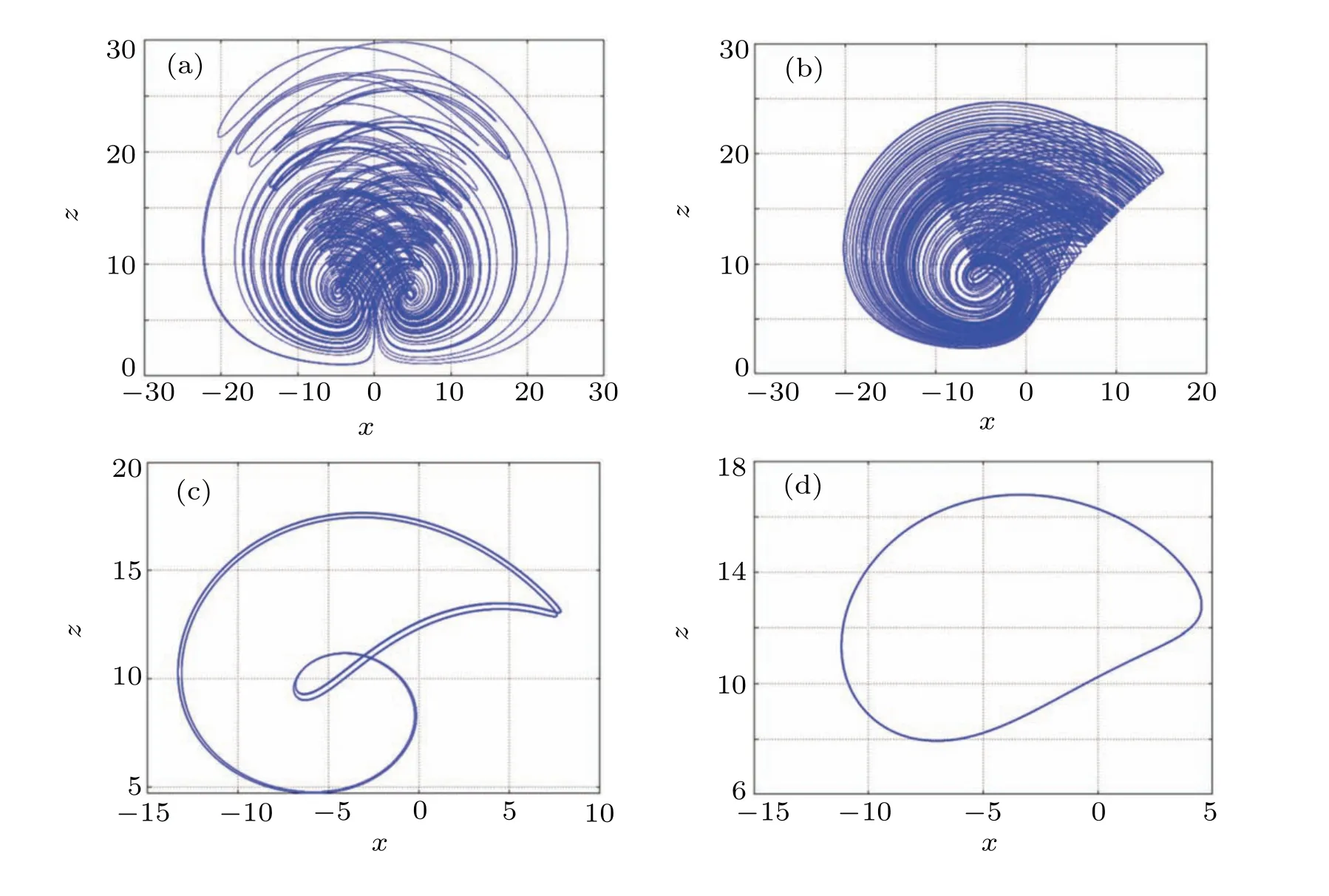
Fig.9. Hidden attractor phase diagrams with different k values: (a)k=1,(b)k=8,(c)k=12,(d)k=30.
In 2004,Gottwald and Melbourne proposed a binary test method[30]to test whether nonlinear systems have chaotic behavior,which is called 0–1 test method. The basic idea of this method is to establish a random dynamic process for the data,and to study the results of the scale evolution of the process over time. If the trajectory of the system on thep–splane is similar to the unbounded behavior of brownian motion, then the system is chaotic. On the contrary,if the trajectory on the plane is bounded,then the system is periodic. Let the parametersa=5,b=10,c=2,d=0.1,e=1,f=0.1,k=1,and the initial values be(1,1,1,10),and the 0–1 test results of the system(7)on thep–splane are shown in Fig.10(a). Keeping other parameters unchanged,letk=30,the 0–1 test result of the system is shown in Fig.10(b). Obviously,the trajectories shown in Fig.10(a)are unbounded,and the trajectories shown in Fig.10(b)are bounded. The 0–1 test results correspond to the simulation results of the attractor phase diagram, which further shows that the parameter changes have an impact on the dynamic behavior of the system.

Fig.10. The 0–1 test results of system(7): (a)k=1,(b)k=30.
3.5. Hidden multistability-dependent on initial memristor values
Leta=5,b=10,c=2,d=0.1,e=1,f=0.1,k=0.1,the initial value is (1, 1, 1,w(0)). When the initial value of memristorw(0) changes within the range of [−30,30], the four Lyapunov exponent spectrums of the system (7) changing withw(0) are shown in Fig. 11(a), represented by blue,red,green,and pink curves respectively. Obviously,the maximum Lyapunov exponent of the system is always positive,so the system is always in a chaotic state under the corresponding parameters and initial values, and it is inferred that the system may have infinite hidden attractors. The bifurcation diagram of state variablezchanging withw(0) is shown in Fig. 11(b), whose bifurcation trajectory changes corresponding to Fig.11(a).
Whenw(0)values are−5, 0, and 5, the system presents three hidden coexisting attractors with different topologies,which are represented by red, blue, and green trajectories respectively, their phase diagrams are shown in Fig. 12. When thew(0)value is 0,four scroll attractors appear in the system,and when thew(0) value is−5 and 5, two double scroll attractors with different structures appear in the system, which indicates that the system(7)has hidden heterogeneous multistabilities.
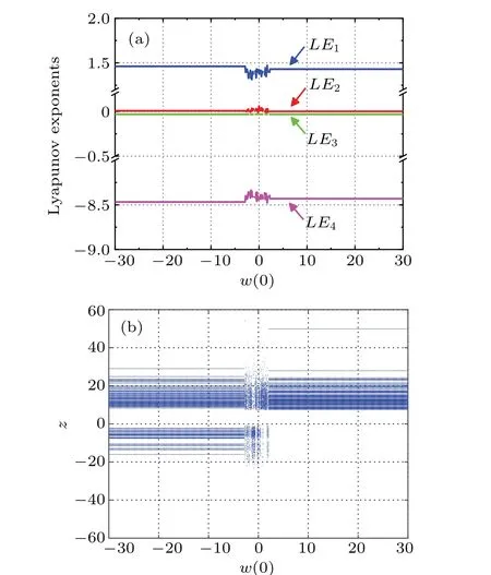
Fig.11. Lyapunov exponent spectrums and bifurcation diagram varying with w(0): (a)Lyapunov exponent spectrum,(b)bifurcation diagram.
Whenw(0)values are−10,−20,and−30,the first kind of hidden coexisting attractors with the same topology appear in the system, which are represented by red, green, and pink trajectories respectively, their phase diagrams are shown in Fig.13. When thew(0)values are 10,20,and 30,the second kind of hidden coexisting attractors with the same topological structure appear in the system,which are represented by blue,orange,and gray trajectories respectively,their phase diagrams are shown in Fig. 14. Obviously, the topological structure of attractors is the same,but the spatial positions are different,so the system(7)has hidden homogenous multistabilities in these two cases.
Whenw(0) values are−25,−15,−6, 0, 6, 15, 25, the phase diagrams are shown in Fig.15. In fact, the system can produce more or even infinite hidden attractors by changing the initial conditions of the memristor. Therefore,it is inferred that the system(7)also has hidden super multistabilities.

Fig.12. Hidden coexisting attractors with different topologies. (a)The 2D plot in x–z plane,(b)the 2D plot in y–z plane,(c)the 2D plot in z–w plane(d),the 3D plot in w–z–x space.
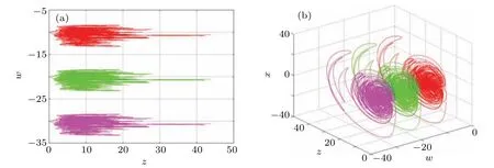
Fig.13. The first kind of hidden coexisting attractors with the same topology. (a)The 2D plot in z–w plane;(b)the 3D plot in w–z–x space.
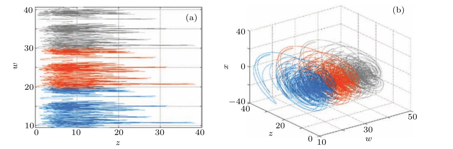
Fig.14. The second kind of hidden coexisting attractors with the same topology. (a)The 2D plot in z–w plane,(b)the 3D plot in w–z–x space.
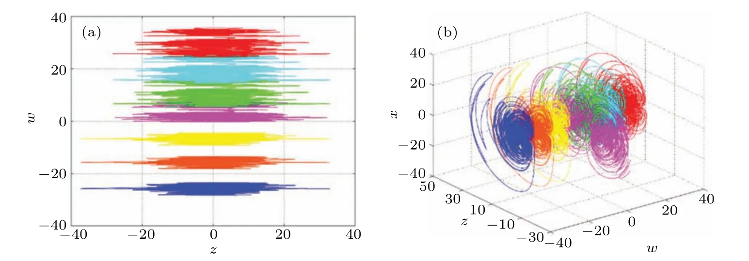
Fig.15. Infinite number of hidden coexisting attractors. (a)The 2D plot in z–w plane,(d)the 3D plot in w–z–x space.
3.6. Hidden transient chaos and state transition behavior
Transient chaos refers to the special phenomenon that the system is in a chaotic state for a period of time, but with the evolution of time, it changes into another periodic or chaotic state. In this section,the hidden transient chaos and state transition behavior of the system(7)depending on the initial condition of memristor are discussed. Set the parametersa=5,b=10,c=2,d=0.95,e=1,f=0.1,k=0.1,the initial condition is(0,−1,−5,w(0)),set the simulation timet=1000 s,and the step size is 0.01. Whenw(0)=10, the time-domain waveform of the state variablexis shown in Fig.16(a). It can be observed that the time-domain waveform changes from disorderly to regular in the vicinity oft=72 s,the system has a state transition. In addition,the local waveforms near the state transition are amplified for easy understanding. Int1∈[0,72]andt2∈(72,1000]thex–zplane phase diagram of the motion trajectory of the system is shown in Fig.16(b). Obviously,the attractor with chaotic characteristics appears in the short time beforet=72 s,and the periodic limit cycle appears in a long time aftert=72 s,which fully shows that the system has hidden transient chaos under the corresponding parameters and initial conditions.
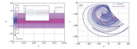
Fig.16. The t–x waveform and the x–z phase diagram when w(0)=10,(a)t–x,(b)x–z.
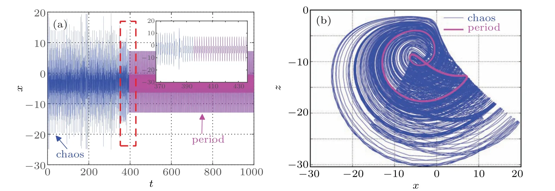
Fig.17. The t–x waveform and the x–z phase diagram when w(0)=100,(a)t–x,(b)x–z.

Fig.18. The t–x waveform and the x–z phase diagram when w(0)=180,(a)t–x,(b)x–z.
Similarly,whenw(0)=100,the system has a state transition neart=395 s. The time domain waveform and phase diagram of state variablexare shown in Figs.17(a)and 17(b),the simulation results are similar to the former, but the existence time of the transient chaos is obviously prolonged.Whenw(0)=180, set the simulation timet=1500 s, and the time-domain waveform of the state variablexis shown in Fig.18(a),which is completely different from the former two cases. At this time,neart=608 s,the system turns to another kind of chaos rather than period. The phase diagram trajectory in thex–zplane is shown in Fig.18(b). It can be seen that the attractors before and after transfer are obviously different.
4. Circuit design and implementation
In order to further observe the chaotic attractor and verify the correctness of the system,based on the previous numerical analysis, the analog circuit of the system (7) is designed and simulated in this section. In the simulation, the operational amplifier,multiplier,resistance and capacitance are used,and the complex dynamic behavior of the system is observed on the analog oscilloscope. The input voltage of analog operational amplifiers is set to+15 V and 15 V,the gain of analog multipliers is set to 1. In order to limit the dynamic range of the state variable to the saturation voltage range of the elements, we compress the values of the state variablesx,y,z,andwto 1/5 times of the original. The dimensionless equation is
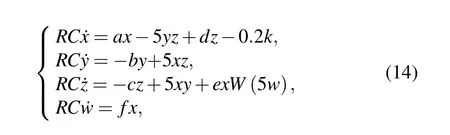
whereRCis the time scale transformation factor. The circuit diagram of system(7)is shown in Fig.19,and the circuit equation is as follows:
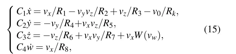
where,vx,vy,vz, andvwcorrespond to the voltages of capacitorsC1,C2,C3,andC4,respectively.

Fig.19. Circuit diagram of chaotic system with five-valued memristor.
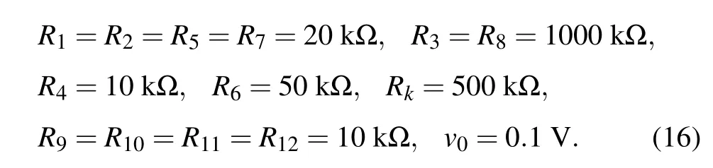
Comparing Eqs. (14) and (15), we getR1=R/a,R2=R5=R7=R/5,R3=R/d,R4=R/b,R6=R/c,R8=R/f,Rk=R/2k,C1=C2=C3=C4=C. LetR= 100 kΩ,C= 10 nF, when the parameters of system (7) area= 5,b=10,c=2,d=0.1,e=1,f=0.1,k=0.1, the parameters of elements are obtained as
Adjust the parameters of the elements in the circuit, and run the simulation to get the double scroll chaotic attractor as shown in Fig. 20. In order to further observe the influence of parameters on the dynamic behavior of the system, the resistance values of the regulatingRkare 6.25 kΩ and 1.67 kΩrespectively. The corresponding circuit simulation results are shown in Figs.21 and 22,which are obviously consistent with the numerical simulation results ofk=8 andk=30. The correctness and physical realizability of the chaotic system based on five-valued memristor are verified.

Fig.20. Circuit simulation results of five-valued memristor-based chaotic system. (a)In the x–y space,(b)in the x–z space,(c)in the y–z space,(d)in the z–w space.

Fig.21. Circuit simulation results when Rk=6.25 kΩ. (a)In the x–z plane,(b)in the y–z plane.
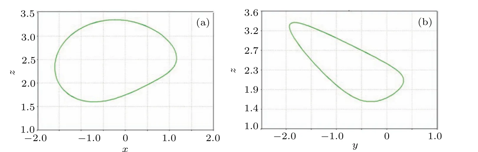
Fig.22. Circuit simulation results when Rk=1.67 kΩ for(a)In the x–z plane and(b)in the y–z plane.
5. Conclusion
In this paper,a five-value memristor model is proposed it is proved that the model has a typical hysteresis loop by analyzing the relationship between voltage and current. Then,the model is introduced into Liu–Chen system and a new memristor-based 4D chaotic system is designed. The dynamic behaviors of the system are analyzed,such as dissipativity,initial value sensitivity and poincare mapping. The results show that the system can generate hidden periodic limit cycles,hidden single scroll attractors, hidden double scroll attractors,and hidden four scroll attractors. Meanwhile,the system also shows extreme sensitivity to initial values of the state variable,and has hidden multistabilities, hidden super-multistabilities,and state transition behavior. Finally, the design and simulation of the memristor-based chaotic circuit are completed,and the results are consistent with the numerical simulation results.This study shows that the five-valued memristor model is suitable for chaotic circuit design, which expands the realization way of the memristor model and nonlinear system, and has potential application value in information security and other fields.

- Chinese Physics B的其它文章
- Physical properties of relativistic electron beam during long-range propagation in space plasma environment∗
- High winding number of topological phase in non-unitary periodic quantum walk∗
- Widely tunable single-photon source with high spectral-purity from telecom wavelength to mid-infrared wavelength based on MgO:PPLN∗
- Control of firing activities in thermosensitive neuron by activating excitatory autapse∗
- Adaptive synchronization of chaotic systems with less measurement and actuation∗
- Dynamics analysis of a 5-dimensional hyperchaotic system with conservative flows under perturbation∗