
Refocusing and locating effect of fluorescence scattering field∗
2021-12-22 06:42JianGongCui崔建功YaXinYu余亚鑫XiaoXiaChu楚晓霞RongYuZhao赵荣宇MinZhu祝敏FanMeng孟凡andWenDongZhang张文栋
Chinese Physics B 2021年12期
关键词:建功
Jian-Gong Cui(崔建功) Ya-Xin Yu(余亚鑫) Xiao-Xia Chu(楚晓霞) Rong-Yu Zhao(赵荣宇)Min Zhu(祝敏) Fan Meng(孟凡) and Wen-Dong Zhang(张文栋)
1State Key Laboratory of Dynamics Testing Technology,North University of China,Taiyuan 030051,China
2The School of Information Science and Technology,Shijiazhuang Tiedao University,Shijiazhuang 050043,China
Keywords: optical focusing,bioimaging,genetic algorithm,centroid locating
1. Introduction
In recent decades, optical imaging inside the scattering medium has become a research hotspot in the interdisciplines of optics,information and biology,which extends a wide range of application prospects in the fields of biological imaging,[1,2]optical acquisition[3]and fluorescence imaging.[4,5]When a coherent light transmits through a strong scattering medium with inhomogeneous refractive index, its intensity would exhibit an exponential decay with the propagation distance,and the light components would be back and forth scattered inside the disordered medium to form a scattering field with a random distribution of the intensity and phase.[6]Therefore,the disordered scattering medium impedes the optical acquisition of depth information, especially the imaging inside biological tissues. As a result, technologies such as all-point scanning and wide-area imaging exceeding several hundred micrometers are no longer applicable. However, wavefront shaping technique based on a spatial light modulator (SLM)modifies the wavefront distribution of the incident beam by measuring the feedback signal from the target point. It is an effective approach to reverse the scattering effect and refocus the beam towards diffraction limit.[7–10]Originally, the feedback signal is received by a detector at the other end of scattering medium,or extracted from the internal scattering paths.For example,in 2007,Vellekoopet al.[11,12]from the University of Twente in the Netherlands adopted the SLM and combined the feedback technique to modulate the signal’s wavefront for the first time, and finally realized the refocusing effect of the light field through a strong scattering medium. Cuiet al.[13]employed a SLM to replace the traditional photorefractive crystals, and achieved the refocusing of the scattering light that penetrated the scattering medium by the optical phase conjugation method. Before that,previous light field refocusing techniques have been realized outside the scattering medium, while in the field of biological imaging, it is more practical to realize optical refocusing and fluorescent bead locating inside biological tissues in a reflective and non-invasive configuration.[14]Thereafter,researchers have proposed a variety of wavefront shaping techniques to achieve the internal focusing within a complex medium,and the most typical one is based on the linear fluorescence microscopy scheme,[15–17]which achieved high-resolution imaging with various contrasts in a shallow level of biological tissues,and conquered the invasive focusing problem plagued the extended target. Most of these methods require to rely on the memory effect of the sample, that is, the collected scattering field is translated with the incident beam,and only thin samples could be wellimaged.[18–20]Thus, the non-invasive deep focusing of extended or multiple targets using linear excitation fluorescence feedback needs to be resolved immediately.
In this paper, fluorescent beads integrated with a scattering medium are introduced into a con-focal microscopy system,and a refocusing,that is,the contrast optimization model for the collected fluorescent scattering field is established.Since the excited fluorescence is non-polarized and spatially incoherent, the detected light intensity is a scalar sum of the fluorescence intensity distribution from each individual fluorescent bead, which greatly attenuates the total field contrast related to the single fluorescent bead contrast and the number of beads.Employing the nonlinear feedback mechanism of the detected field contrast,an effective and feasible method to refocus the fluorescent scattering field and further locate the fluorescent beads is proposed. The improved genetic algorithm that controls the SLM phase distribution can offset the divergence effect of the scattering medium to a certain extent,and refocus the scattering fluorescence field to the vicinity of fluorescence beads. Based on the fact that the contrast is mainly determined by the second central moment of the field intensity,the positions of all the fluorescent beads could be precisely reconstructed by locating the centroids of focused Gaussian envelopes. Finally, various factors significant to the practical scenarios are analyzed to obtain the relevant constructive instructions.
2. Theoretical model of the contrast of scattered light field
2.1. Theoretical model
In the case of linear excitation scheme, the intensity of the emitted fluorescence is directly proportional to the power of the excitation light. Since each fluorescent bead radiates a broadband and non-polarized fluorescence, and all the beads inside the scattering medium are spatially incoherent, the detected fluorescence scattering field is the scalar sum of the intensity from all fluorescent components. Since the former is mainly related to the initial contrast of a single bead and the number of fluorescent beads,[6]this effect further reduces the contrast of scattering fluorescent light, and the contrast is expressed by

whereIis the optical field intensity captured by the detector,and〈·〉means the spatial average of a two-dimensional(I2orI)distribution in pixel scale,which is sampled from the fluorescence image. When the fluorescent beads in the field of view are excited by a spatially modulated planar wave,the beads at different positions receive different exciting light power, and the detected intensity is the sum of each fluorescent component and the experimental noise,which is shown as

whereICCD,Iflu, andIexcare the detected intensity by the camera,fluorescence intensity and excitation intensity,respectively.neis the experimental noise introduced by the measurement system,andwkis excitation coefficient corresponding to thek-th fluorescence bead. Therefore,by spatially modulating and optimizing the excitation intensity, it is possible to artificially control the distribution of excitation field upon different fluorescent beads,and when the detected field is refocused onto a certain fluorescent bead, the contrast of the scattering fluorescence reaches its maximum.
Since each phase mode of the SLM takes discrete values in the interval[0,2π],the operating region(the area where the excitation light passes through)corresponds to a different phase matrixΦSLM=ηSLM·∆ϕ.Here,ηSLMis the modulation matrix, and ∆ϕis the modulation accuracy. It could be seen that the modulation matrix directly determines the distribution of the excitation light field upon different fluorescent beads,and the intensity modulation period isπ. The relationship between the detected intensity and the phase mode is obtained as

whereak,ϕkandbkare amplitude, phase, and offset coefficients of the excitation field at thek-th bead, respectively.Since the contrast of the fluorescent scattering field is related to the second central moment of the intensity, and the phase mode of SLM indirectly and periodically modulates the detected intensity,it is reasonable to take the field contrast as the cost function of the following optimization algorithm.
When a broadband excitation light illuminates the fluorescent beads, the former contains multiple spectral components that inevitably brings a more complicated effect on the scattering fluorescence.Assuming that the excitation spectrum is relatively flat in the range ∆λ=λ2−λ1, the total excitation intensity is the integral of the intensity density within the wavelength range
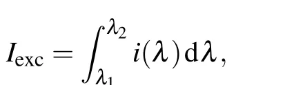
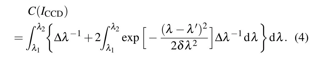
wherei(λ) is regarded as the corresponding intensity atλwhich is infinitely small, and the contrast of scattering fluorescence isC(i(λ))= dλ/∆λ. Meanwhile, different spectral components would interfere with each other and further modify the contrast. The introduced increment of the contrast is

whereδλis the transmission bandwidth of the scattering medium. Therefore, the contrast of the fluorescence scattering field detected by the CCD camera is equal to the sum of the contrast introduced by all spectral components within the excitation bandwidth
2.2. Experimental setup
The optical con-focal system to investigate the refocusing and locating effect of the fluorescence scattering field is shown in Fig. 1(a). A 532 nm monochromatic laser (Coherent Sapphire) beam expanded by a combination of lenses is firstly modulated by a SLM (Kilo-DM segmented, Boston Micromachines Corp.), then it passes through a dichroic mirror (transmitting the wavelength shorter than 550 nm,while reflecting the wavelength longer than 550 nm) and focused on fluorescent beads (FluoSpheresTMPolystyrene Microspheres, 1.0 µm, red fluorescent light 580/605) behind a scattering medium by an objective with a magnification of 20× (NA = 0.4). These beads are diluted multiple times to obtain samples with different distribution densities (Fig. 1(b) is an optical image of the evenly distributed fluorescent beads, and most of the spatial distance is more than 12 µm), and this corresponds to different number of beads within the field of view. At first, all the fluorescent beads are illuminated to produce an omnidirectional broadband non-polarized fluorescence. After being collected by the objective, it returns to the dichroic mirror with a proportion of reflected excitation light. Only the fluorescence is reflected and most of the excitation light is transmitted.After being filtered by the combination of optical filters(532 nm long pass +533 nm notching, Thorlabs), the relatively pure scattering fluorescence is collected by the upper CCD camera to obtain a refocused and optimized target image(as shown in Fig. 1(c)). The laptop is connected to the CCD camera and SLM at the same time. On one hand, it controls capture of the scattering fluorescence and calculates the contrast in each iteration cycle,and on the other hand,it writes the staged optimal phase mode into the SLM.

Fig.1. (a)The con-focal setup of measuring and refocusing the fluorescence scattering field (DM: dichroic mirror, SM: scattering medium);(b) optical image of the fluorescent beads; (c) intensity distribution of the fluorescence scattering field.
3. Theoretical model of the contrast of scattered light field
Initially, a transmission configuration (including a laser,the scattering medium and a powermeter) is established and the transmission coefficients of the scattering medium are calibrated by fitting the theoretical model and experimental data.Then, the contrast of the scattering fluorescence images collected by the optical con-focal system and correlation coefficient with the Gaussian curve are taken as the cost function,and a genetic algorithm is improved for refocusing optimization. Finally, the Gaussian characteristic areas of the optimized images are selected,and the centroid positioning algorithm is performed to locate all the fluorescent beads with an error analysis.
3.1. Optical characteristics of the scattering medium
Scattering medium is one of the most significant factors that affects the intensity distribution of the scattering fluorescence. Its multiple-scattering mechanism introduces intense complicated random interference to the amplitude and phase of the light field,and inevitably disturbs refocusing process and locating accuracy. According to the boundary conditions of the diffusion theory,[21]a configuration composed of a monochromatic laser, scattering medium (no fluorescent beads) and a power detector is established to measure the transmission coefficients. In the experiment, different thickness(1,3 and 6 layers)of the scattering films are selected and the transmission power is measured,respectively. Theoretical model is fitted with the experimental data,and the absorption coefficientαand transmission free pathltof the scattering medium are calculated to be 1.2 mm−1and 700µm. According to the Lambert law of scattering, the transmission coefficient exponentially decreases with the transmission length,as shown in Fig. 2(a). Three solid lines are transmission curves obtained from different scattering free pathsls, and by fitting with the experimental data(blue dots),the scattering free pathltis around 140µm. At this point,the 0.86 anisotropic coefficient illustrates that forward scattering dominates the scattering process within our scattering films. To study the effect of broadband excitation light on the scattering fluorescence contrast, the 532 nm monochromatic laser is replaced with a combination of supercontinuum source (NKT SuperK Extreme) and optical filters with different bandwidth, as shown in Fig.2(b). Within the forbidden bandgap of the fluorescent beads, the contrast of the scattering fluorescence images under different bandwidths (1 nm, 3 nm, 11 nm and 40 nm) of the excitation light is 0.8,0.78,0.37 and 0.16,which fits well with the theoretical model.Reducing the excitation bandwidth could effectively improve the initial contrast of fluorescence.Further studies have shown that the contrast is also affected by the characteristics of the fluorescent beads and the scattering medium.
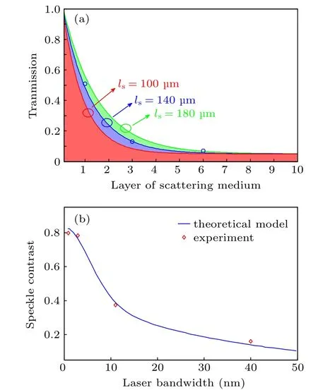
Fig. 2. (a) The plots of transmission and thickness of scattering medium; (b) the fluorescence contrast at different excitation bandwidths.
3.2. Refocusing of scattering fluorescence based on improved genetic algorithm
Genetic algorithm is suitable for optimization problems with multiple parameters and a large-scale solution space,[22,23]which could be transplanted in the refocusing optimization process where SLM generates a large number of phase modes. The procedure of the improved algorithm is described as follows: Firstly,a certain number(P=60)of individuals (namely, phase matrixΦSLM) are pseudo-randomly generated,and the phase values follow the uniform probability distribution. After all individuals modulate the scattering fluorescence image,both the contrastCand correlation coefficientR(fitted with the Gaussian envelope)are weighted to calculate the cost functionF=(1−s)·C+s·R(whereinsis the adaption coefficient),which serves as the ranking criterion. Then,the roulette algorithm is conducted to selectP/2 pairs of parents in turn and randomly generate binary reproduction templateT,and the offspring satisfies thech=ma·T+pa·(1−T)relationship (wheremaandparepresent the parents). In the variation stage, the variation coefficientMis mainly determined byRand satisfiesM= (M0−M1)·exp(−R)+M1,
whereM0=0.1 andM1=0.01 are initial and final variation coefficients,respectively.On this basis,excellent offspring are effectively retained and the cost function is calculated again.Finally,the lastP/2 parents should be replaced with the excellent offspring and the new population are rearranged according to the cost function,as a new round of parents to multiply until the optimal cost function value no longer changes. At first,the intensity of the scattering field is irregularly distributed,the contrast value dominates the whole process and quickly pushes the algorithm to converge to a high-contrast stage(400 iterations). With the establishment of refocusing distribution, the correlation coefficient with the Gaussian curve gradually occupies the process, and the optimized light field further converges. To be noted,the algorithm uses 1024 phase modes and iterates approximately 1100 times to achieve the optimization. In the experiment, four fluorescent beads integrated on a single-layer scattering medium are investigated,which are easily adsorbed by van der Waals force. As shown in Fig. 3(a), four optimized curves focusing on different fluorescent beads are selected in turn, in which can be found that the contrast enhancement factor strongly depends on the fluorescent beads. The contrast converges quickly in the first 400 iterations,and oscillates around a certain value after 1000 times, and the enhancement factorη= 10·lg(C1/C0) (C0andC1are contrast before and after the optimization)reaches to 12.8 dB. At this time, the achieved refocused scattering fluorescence presents a two-dimensional Gaussian distribution. The curvature of the foci, namely, the reciprocal radius,can be calculated by fitting the 20%peak intensity contour to the convex hull, and the larger this value is, the better focusing performance we obtained. The intensity probability density function (PDF)P(I) = exp[(−I/〈I〉)/〈I〉] of the excitation light originating from laser follows the Rayleigh distribution,[24]whereas, after the random disturbance of the scattering medium, the PDF of the detected refocusing light field follows the Gaussian distributiony= exp[−(x −0.97)2/2·0.252],as shown in Fig.3(b).

Fig.3. (a)The refocusing optimization curves of fluorescence contrast from different beads;(b)the probability density function of the focus.
3.3. The centroid positioning of fluorescent beads with sub-pixel precision
With different selections of the initial condition in the genetic algorithm,it could be observed that the fluorescent center with good refocusing effect basically coincides with the positions of the fluorescent beads, which contains the spatial information to a certain extent. At this time,the observed refocusing points basically results from the fluorescent beads,and the SLM modulating effect counteracts two scattering processes in the system. The centroid positioning accuracy of the refocusing point primarily depends on the foci shape and the system noise. Here,the sub-pixel centroid positioning method is employed to accurately locate all the fluorescent beads. Figure 4(a) shows the fluorescence image composed of numerous points denoted as pixels with a two-dimensional integer coordinates,and the corresponding envelope illustrates the intensity distribution of a refocusing point (No. 2 in Fig. 3(a)).Two orthogonal lines (red dashed lines) passing through the peak position are selected for projection. After these curves are fitted, the rectangular box with a valley intensity of more than 60%is intercepted as a characteristic area(marked in red dotted line) of Fig. 4(b). This scale corresponds to a spatial length of about 2 µm, providing an upper limit for the resolution of adjacent fluorescent beads. To improve the locating accuracy,the number of effective pixels is increased by interpolation within the area. The coordinates of the fluorescent beads are obtained by the square gray weighting algorithm as
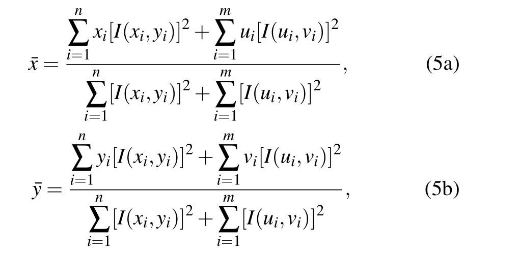
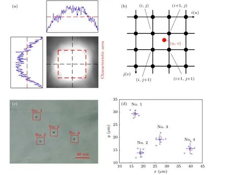
Fig. 4. (a) The intensity distribution of the fluorescence scattering field, red marked region: characteristic area for centroid positioning;(b)diagram of sub-pixel accuracy centroid localization algorithm; (c)optical image of the fluorescent beads, targets are marked; (d)the reconstruction of beads’positions.
whereI(x,y)is the intensity of the original pixel(x,y),I(u,v)is the intensity of the interpolation point(u,v),nandmare the original and interpolated pixel numbers, respectively. After calculating the coordinates of the centroid position,the result is one or two decimal places, and by spatial-to-spatial mapping, that is two-dimensional coordinates to spatial distance,the sub-pixel precision could be achieved,which means the reconstructed positions might be fall between pixels.Figure 4(c)is an optical image and Fig.4(d)corresponds to reconstructed image with error bars of the fluorescent beads.In Fig.4(d),the red icons represent the actual positions while the blue icons are the relocating data and error bars of five repeating refocusing processes. The expectation of locating error is 4.2µm. Since the convergent position of the refocusing algorithm relates to the initial condition, the overall average should be closer to the actual position of the fluorescent beads with an increasing number of measurements. In this experiment,five locating results are randomly selected for each fluorescent bead,and the locating accuracy is further improved.
4. Theoretical model of the contrast of scattered light field
4.1. The influence of measurement noise
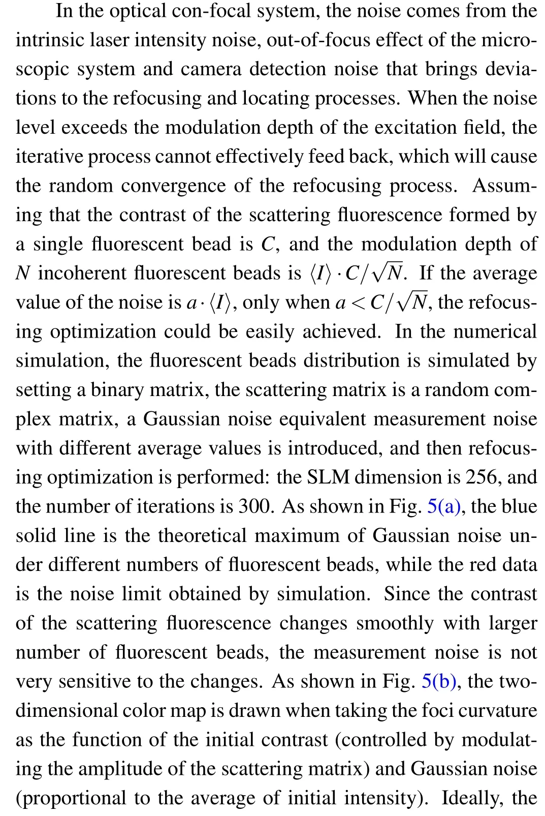


Fig. 5. (a) The noise level as a function of the number of fluorescent beads; (b) foci curvature as a function of fluorescence contrast and Gaussian noise level.
4.2. The influence of experimental parameters
As mentioned above,the fluorescent beads(target)would produce a broadband fluorescence when excited, and their overall contrast is inversely proportional to the square root of the bead’s number. Five samples on a single-layer scattering medium are selected in experiment with 4, 9, 16, 25, and 40 fluorescent beads,respectively.The contrast enhancement calculated after refocusing are plotted in Fig.6(a).As the number of fluorescent beads increases, the interference effect would occur between the excited fluorescent light, making it difficult for scattering field to refocus and its relationship tends to be more like a negative exponential function. In order to explore the relationship of the enhancement factor and phase mode,three types of SLMs with a dimension of 256,1024,and 4096 are subsequently replaced in Fig.1(a)and performed the optimization process, as shown in Fig. 6(b). Intrinsically determined by the modulation mechanism,its spatial dimension should ben-th power of 2, so that these values are selected to roughly investigate the enhancement dependence. As the optimized dimension increases to the power of two,the spatial modulation of the light field is more refined,and the contrast is improved by nearly 3.6 dB,but the calculation time increases exponentially,which is a major drawback that limits the practical applications. When the dimension exceeds 1024, contrast improvement becomes to saturate, indicating a tradeoff between the efficiency and enhancement. In the application of refocusing and locating of the scattering field,the characteristics of the scattering medium and the long-term stability of the system are two important factors that should be concerned,the former are comparable to those of biological tissues, and the number of layers is related to the thickness of tissue.The latter determines the stability of feedback signal during the refocusing process that directly affects the performance of focusing and locating in practice. As shown in Fig.6(c),the number of fluorescent beads is 4,and the number of layers of the scattering medium are sequentially selected as 1, 2, 3, 5, and 6 for refocusing. The thickness increase of the scattering medium would linearly extend the scattering distance and cause different degrees of focusing deviation during refocusing,resulting in a rapidly deteriorate refocusing of the light field. The critical thickness of the scattering medium is not calibrated in this paper,but a few cases under the six-layer thickness(600µm)is already not ideal to refocus. Although it can be further optimized by increasing the excitation light power,the fluorescent beads are prone to be bleached. To investigate the locating deviations, a sufficiently thick medium cannot achieve refocus with a large curvature, and on the other hand, it introduces a certain longitudinal deviation to the centroid positioning,both of which would lead to a decrease in locating accuracy.In case of the system stability, images of the fluorescence scattering field are collected with our experimental setup in the interval of 10 minutes,and the inner-product correlation calculation is performed with the initial image,as shown in Fig.6(d). Here,the defocusing factor caused by the gravity effect is ignored for the reason that this can be easily resolved by an autofocus algorithm or an advanced calibration datacube. The value of zero means the image is totally different from the initial image and unable to refocus and locate, and one means the two images are exactly the same. It can be seen that the experimental setup is long-term stable. With the passage of time,there is almost no drift or out-of-focus problems,and the overall average value remains around 0.968 after 24 hours.

Fig. 6. Contrast enhancement as a function of (a) the number of beads and (b) spatial modulating parameter; (c) the influence of scattering medium thickness on foci curvature and localization error;(d)the correlation of fluorescence scattering field with time.
5. Conclusion and perspectives
The forward scattering accounts for a larger proportion in the optically calibrated scattering medium and could be equivalent to biological tissues. Meanwhile, since the fluorescent beads can be compared to labeled cells,this investigation provides the feasibility, that is, optimizing the contrast of fluorescence scattering field collected by an optical con-focal system could realize a non-invasive and precise reconstruction of fluorescence beads inside biological tissues. Taking the contrast of scattering fluorescence and Gaussian correlation coefficient as cost function,our improved genetic algorithm could accurately control the excitation light wavefront in real time,and subsequently converge to refocus on each individual fluorescence bead. The optimal contrast enhancement reaches to 12.8 dB, and the locating error is no more than five microns.Based on this system, this refocusing and locating technique is primarily limited by the camera’s exposure time. Since one exposure(50 ms)is required in each iteration cycle,the whole procedure requires nearly one minute, which also greatly restricts the refocusing effect and locating accuracy. As the experimental noise cannot be avoided during the measurement,and when its intensity exceeds the initial contrast of the fluorescent beads,it is not easy to achieve refocusing with this improved algorithm. In order to further expand the application of this technique,measures such as reducing measurement noise,decreasing the number of fluorescent beads and the thickness of the scattering medium, increasing the intensity of the excitation light power (below bleaching threshold), and multiple locating measurements should be considered to achieve a higher reconstruction accuracy and imaging quality.
猜你喜欢
工会博览(2022年33期)2023-01-12
——第十六届中国医院院长年会特辑(上)
中国医院院长(2022年17期)2022-10-14
乐山师范学院学报(2021年9期)2021-11-08
中国化肥信息(2021年6期)2021-08-21
华人时刊(2021年19期)2021-03-08
金秋(2020年4期)2020-08-18
中国粮食经济(2018年3期)2018-12-27
中国共青团(2016年9期)2016-11-11
工会信息(2016年1期)2016-04-16
支部建设(2013年15期)2013-09-08

- Chinese Physics B的其它文章
- Transient transition behaviors of fractional-order simplest chaotic circuit with bi-stable locally-active memristor and its ARM-based implementation
- Modeling and dynamics of double Hindmarsh–Rose neuron with memristor-based magnetic coupling and time delay∗
- Cascade discrete memristive maps for enhancing chaos∗
- A review on the design of ternary logic circuits∗
- Extended phase diagram of La1−xCaxMnO3 by interfacial engineering∗
- A double quantum dot defined by top gates in a single crystalline InSb nanosheet∗