
Multi-frequency focusing of microjets generated by polygonal prisms
2022-03-12 07:44YuJingYang杨育静DeLongZhang张德龙andPingRangHua华平壤
Chinese Physics B 2022年3期
关键词:平壤
Yu-Jing Yang(杨育静), De-Long Zhang(张德龙), and Ping-Rang Hua(华平壤)
School of Precision Instruments and Opto-electronics Engineering,and Key Laboratory of Optoelectronic Information Science&Technology(Ministry of Education),Tianjin University,Tianjin 300072,China
Keywords: photonic microjet,hexagonal prism,harmonical frequencies,localized surface plasmon resonance
1. Introduction
To improve the resolution in applications such as in microscopy, it is required to consider the limitation imposed by electromagnetic wave diffraction.[1]Over the past years,some researches have been done to solve this problem,[1-9]such as metamaterials,[2,3]diffractive optics,[1]and microspherical particles.[4-9]Among these, a typical method to obtain the subwavelength resolution is to produce photonic nanojet by wavelength-sized dielectric scatterers, such as microspheres and microcylinders,[7]under the irradiation of plane wave.Recently,the methods of producing terajet by cuboids at terahertz and sub-THz frequencies have also been proposed both in simulation calculation and in experimental manufacture.[10,11]It has been verified that the refractive index ratio between the cuboid and the background medium should be less than 2 to generate a terajet just at the output face of cuboid. In the case of air background medium,the cuboid with an optimal refractive index of 1.41 can generate a terajet with power enhancement~10,FWHM~0.47λ,and focal length~0.[11]
In this work, we investigate the effect of the shape of polygonal scatterer on power distribution of microjet generated under the irradiation of plane wave. We also investigate the effects of harmonic frequencies and presence of an Au sphere in the microjet on the power distribution. Firstly, we study the microjets generated by scatterers of different polygonal prisms,and find that the microjet generated by the hexagonal prism displays better features that are characterized by following three parameters: (i)power enhancement, which is defined as the ratio between the power densities at the point of focus with and without the presence of scatterer, (ii) focal length(FL),which is defined as the distance between the position of the maximum power density along theyaxis and the position of output face,and(iii)FWHM at focal position and output face, which is defined as full width at half-maximum along the transversalxaxis. Secondly, we propose a doublelayer scatterer,which is composed of a Teflon hexagonal prism as the outer layer and a semiconductor cuboid as the inner layer,and study the effects of refractive index,size,and shape of the inner insert on the features of microjet. According to the three characteristic parameters, we obtain an optimized scatterer and further study the multifrequency focusing characteristics of microjets generated. Thirdly,we also explore the function of Au sphere present in the center of the microjet.
2. Structural model, principle, and numerical method
Figure 1(a)shows the schematic diagram of bottom faces of different prismatic scatterers,including triangular,quadrangular,hexagonal,octagonal prisms and cylinder. To locate microjets just on the output face of scatterers (FL=0), all the adopted prisms, with the heights along thezaxisH=1.2Rand the bottom faces inscribed on the same circle with radiusR=8.57 mm, possessed the same optimal refractive indexn=1.41(Teflon).[10,11]Figure 1(b)shows the schematic diagram of bottom face of the proposed double-layer scatterer. The outer Teflon hexagonal prism has a refractive indexnside=1.41 and a side lengthLside=Ron thexyplane,while the semiconductor interior cuboid has a refractive indexninsertand a side lengthLinsertalong thexaxis andyaxis.
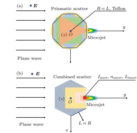
Fig.1. Schematic diagram of bottom faces of(a)different prismatic scatterers, including triangular, quadrangular, hexagonal, octagonal prisms, and cylinder, and (b) proposed double-layer scatterer composed of an outer Teflon hexagonal prism and an inner semiconductor cuboid under irradiation of a polarized plane monochromatic electromagnetic wave.
For convenience,anxyzCartesian coordinate system was fixed in the center of the prismatic scatterers. Az-polarized plane monochromatic wave was incident into the scatterers along theyaxis. In essence, the overlap of power flow scattered by prisms resulted in the formation of a microjet spot,which is just on the output face of the scatterer as shown in Fig.1.The formation of the microjet spot could be simply considered as the focusing of the scattered wave by a prism lens.It is obvious that a higher refractive index scatterer results in a microjet with a shorter focal length(FL<0)and a stronger light intensity. Considering our expectation for nearly zero FL and strong power enhancement,we adopted a double-layer scatterer composed of an inner cuboid with a lower (higher)refractive index and an outer hexagonal prism with a higher(lower) refractive index. In the case that the interior cuboid has a lower refractive index than that of the outer prism, the presence of cuboid gives rise to the focal length and hence makes the microjet just located at the output face of the scatterer.In the case that the interior cuboid has a higher refractive index, it just has an opposite effect. So, in this sense, the inner cuboid with a lower(higher)refractive index functions as a buffer(acceleration)layer.
Aiming at the structure depicted in Fig.1,we conducted numerical simulation on power distributions of the light wave scattered by prisms with different shapes. The simulation was carried out with the aid of a commercial software CST microwave studio and a transient solver in time-domain was employed.A hexahedral mesh and open boundary condition were adopted. The simulation was also performed on an Au sphere with a varied diameter placed in the center of the microjet generated by the double-layer scatterer.
3. Numerical results and discussion
3.1. Characteristics of microjets generated by scatterers of different polygonal prisms
First of all, we study the effect of prismatic scatterer’s shape on the power distribution characteristics of the microjet. As shown in Fig. 2(a), under the irradiation of plane wave withλ=R=8.57 mm, all the polygonal prisms can generate microjets. Among these polygonal prisms, the triangular type one generates a decentralized but not compact microjet. By appropriately designing the angles of the triangle bottom face of the triangular prism, the microjet generated can be shaped. The argument is clarified by Fig. 2(b),
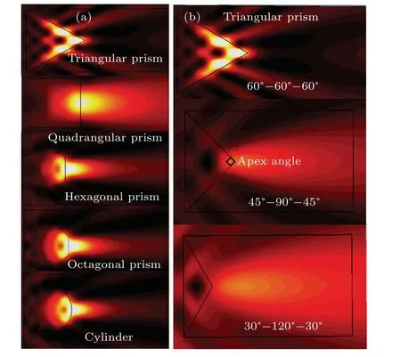
Fig. 2. (a) Contour of power flow scattered by triangular prism, quadrangular prism,hexagonal prism,octagonal prism,and cylinder with λ =R=8.57 mm, and (b)contour of power flow scattered by triangular prism with the angles of triangle bottom face: 60°-60°-60°, 45°-90°-45°, and 30°-120°-30°.
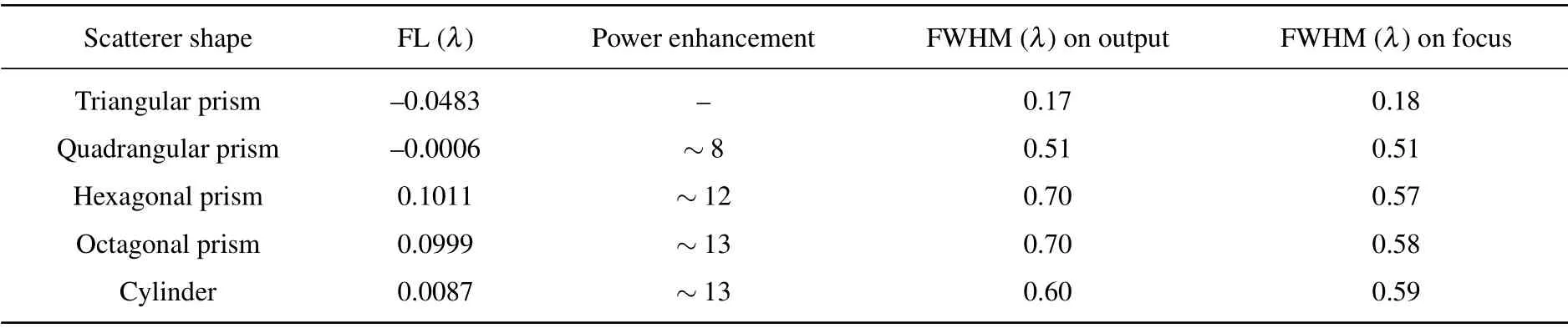
Table 1. Performances of microjets generated by different three-dimensional dielectric prisms with n=1.41 under the irradiation of plane wave with λ =R.
where the results of three different triangular prisms with the angles of 60°-60°-60°, 45°-90°-45°, and 30°-120°-30°are comparatively shown. It can be seen that the width and focal length(hence the shape)of the microjets change considerably as the apex angle is increased from 60°to 120°. Since in the case of triangular prism the output face is reduced into a line,it increases difficulties in using microscopy. Thus,we no longer carry out further study of the triangular prism.
The data in Table 1 show the power enhancement, FL,and FWHM of the microjets generated by different polygonal prisms,including triangular,quadrangular,hexagonal,octagonal prisms, and cylinder separately. As the scatterer is changed from quadrangular to hexagonal prism,the power enhancement of microjet increases from 8 to 12 and the FWHM increases from 0.51λto 0.57λ. As the edge number of bottom face of polygonal scatterer further increases from the hexagonal prism, the increase of power enhancement then slows down, only from 12 to 13. Instead, the FWHM continuously increases with the edge number of the polygonal scatterer increasing. Thus,the hexagonal prism is a compromised choice among these prismatic scatterers. The microjet generated has a comparatively strong power enhancement~12 and a comparatively narrow FWHM~0.57λat the focus, but its focal length is~0.1011λ >0. Considering that the scatterer with a higher refractive index can generate a microjet with a shorter FL, a double-layer hexagonal scatterer formed by an inner cuboid with higher refractive index and an outer Telfon hexagonal prism is proposed to generate a microjet with better features as shown in Fig.1(b).
3.2. Characteristics of microjets generated by combined double-layer scatterers
For the double-layer hexagonal scatterer in Fig.1(b),we comprehensively study the effects of refractive indexninsert,side lengthLinsert, and shape of the interior layer on the features of microjets generated. For the application such as microscopy, we expect a strong power enhancement to ensure a bright field of view,a narrow FWHM to ensure subwavelength resolution and a zero FL to ensure the imaging position. Besides, we prefer that the light spot still keeps compact (narrow FWHM)within a certain distance along theyaxis and the light intensity decays slowly, which ensures enough room to accommodate the Au spheres of different sizes and facilitate the study of the interaction between metal particle and light(see Subsection 3.4).
3.2.1. Effect of refractive index ninsert of insert on characteristics of microjet
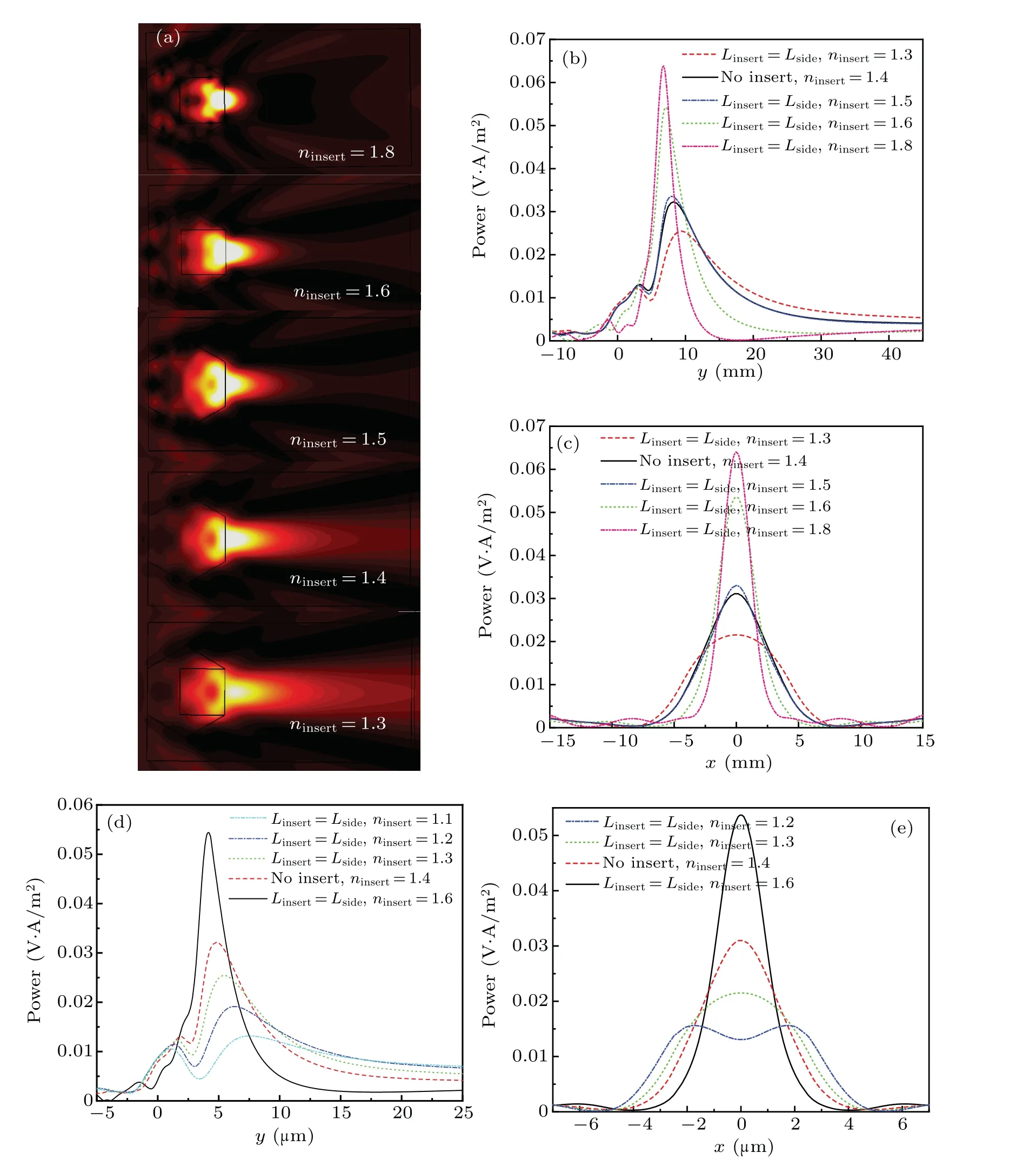
To study the effect of refractive indexninsertof inner cuboid on the features of microjet generated, we adopt the double-layer scatterer withninsert=1.8,1.6,1.5, 1.4,and 1.3 and obtain corresponding contours of power flow shown in Fig. 3(a). Figures 3(b) and 3(c) show the power distribution along theyaxis andxaxis, respectively. Asninsertdecreases from 1.8 to 1.3, the focus position (the position of the maximum power) moves farther along theyaxis, while the maximum power declines significantly and the FWHM widens.
To verify that the refractive index of inner cuboid still follows similar adjusting function for microjets generated by smaller double-layer hexagonal scatterer, we adopt similar double-layer scatterers withLside=5 μm,λ=500 nm,ninsertin a range of 1.1-1.6 and calculate power distribution along theyaxis andxaxis as shown in Figs.3(d)and 3(e),respectively.In Fig. 3(d), whenninsert≤1.3, the microjet generated completely shoots out(FL≫0),and hence can be utilized outside the scatterer. Among the scatterers withninsert≤1.3,the scatterer with a lower refractive index generates a microjet with lower power enhancement. Thus, we select the double-layer scatterer withninsert=1.3 to study the interaction between microjet and Au sphere(see Subsection 3.4)because the microjet generated has a longer FL and a relatively strong power enhancement. Compared with the scatterers of higherninsert,the scatterer withninsert=1.3 generates a microjet with a much flatter power distribution curve along theyaxis as shown in Fig. 3(d). The microjet prolongs for quite a long distance,which facilitates the study of interaction between light and Au sphere located in microjet.
3.2.2. Effect of side length Linsert of insert on characteristics of microjet
In this part, we adopt the double-layer scatterers composed of the outer hexagonal prism(nside=1.4,Lside=5 μm)and inner cuboid(ninsert=1.3,Linsert=Lside,Lside/2,Lside/4,andLside/8) to study the effect of inner cuboid’s side lengthLinserton the features of microjet.As the contour of power flow shown in Fig.4(a),the microjets generated by the double-layer scatterers withninsert=1.3 all shoot out. Figures 4(b)and 4(c)show the power distribution along theyaxis andxaxis, respectively. AsLinsertdecreases fromLsidetoLside/8, the FL becomes shorter, the power becomes larger and the FWHM becomes narrower.It can be explained as the fact that since the refractive index of inner layer is lower than that of the outer layer, the interior cuboid functions as a buffer layer to delay the focusing procedure. The larger the buffer layer, the more obvious the delay effect is. AsLinsertdecreases fromLside/4 toLside/8, the delay effect has changed very little. Thus, we no longer continue to reduceLinsertnor study the effect it brings.
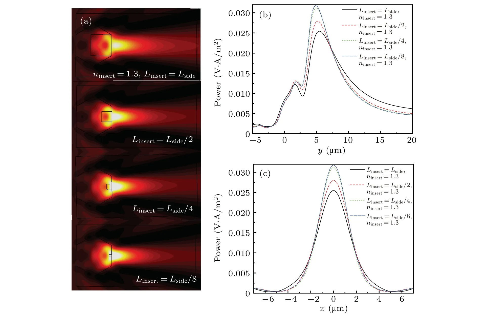
Fig.4. (a)Contours of power flow scattered by double-layer scatterer composed of hexagonal prism(Lside=5 μm,λ =500 nm,nside=1.4)and cuboid(Linsert=Lside,Lside/2,Lside/4 and Lside/8,ninsert=1.3);power distributions along(b)y axis and(c)x axis.
3.2.3. Effect of insert shape on characteristics of microjet
After the discussion of the refractive indexninsertand side lengthLinsertof the inner layer in double-layer scatterer,now we come to study the effect of insert shape on the features of microjet. As shown in Fig. 5, the power distributions of microjets generated by different double-layer scatterers,which separately chooses equal-sized cuboid and cylinder as the inner layer,are very close to each other, along theyaxis andxaxis. This indicates that the shape of inner layer is not an important factor influencing microjet features.

Fig. 5. Power distributions along (a) y axis and (b) x axis of microjets generated by double-layer scatterers composed of outer hexagonal prisms(Lside=5 μm,λ =500 nm)and equal-sized inner layers(ninsert=1.3,Linsert=Lside/4)of different shapes(cuboid,cylinder).
3.2.4. Optimized double-layer scatterer
According to the above discussion,two important factors to influence the features of microjet generated by double-layer scatterer are refractive indexninsertand side lengthLinsertof the inner layer. Thus,we investigate the characteristics of microjets generated by double-layer scatterers with different combinations ofninsertandLinsertas shown in Table 2. With expectations of strong power enhancement,zero FL and narrow FWHM,three double-layer scatterers are selected and marked in yellow in Table 2 for the better features. The first(second,third) selected scatterer is formed by an interior cuboid withninsert=2(1.9,1.8),Linsert=Lside/2(Lside/2,Lside/4)and an outer hexagonal prism withnside= 1.4 andLside=R. The first scatterer generates a microjet with the strongest power enhancement~28.5 and the narrowest FWHM both on focus(~0.241λ)and in output face(~0.262λ),with a nearly zero FL~-0.066λand dz~0.190λ. The second one generates a microjet with a strong power enhancement~25.2,a narrow FWHM on focus (0.264λ) and output face (0.288λ), with a nearly zero FL~-0.060λand dz~0.235λ. And the third one generates a microjet with a power enhancement~14.3,a still narrow FWHM(0.408λ)both on focus and in output face,and an ideal zero FL=0 and the longest dz~0.624λ.
Moreover,we investigate the power enhancement curves of the microjets generated by three selected scatterers,within a distance range of 0-2λ,away from the output face,as shown in Fig. 6(a). The microjet generated by the third scatterer(ninsert=1.8,Linsert=Lside/4)has the flattest power enhancement curve and the slowest power decay. We also investigate the FWHM curve of the microjets in the distance range of 0-λalong theyaxis as shown in Fig. 6(b). The microjets generated by the the first (ninsert=2,Linsert=Lside/2) and second (ninsert=1.9,Linsert=Lside/2) scatterers have much narrower FWHM and more compact light spots. Two microjets still keep narrow FWHM~0.5λwhen the distance isλfar from the output face. With comprehensive consideration of power enhancement, FL, FWHM, and the dz, we select the first double-layer scatterer as an optimized scatterer to analyze the multifrequency focusing features of the microjets in the next part.
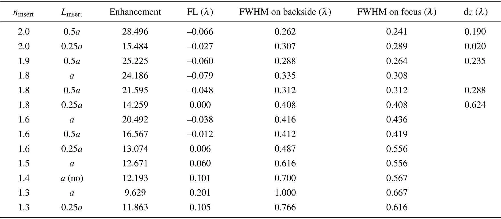
Table 2. Features of microjets generated by double-layer scatterers of different values of ninsert and Linsert (λ =R=8.57 mm).
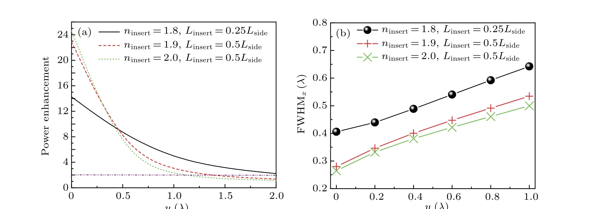
Fig.6. (a)Power enhancement of microjets in distance range of 0-2λ,and(b)FWHM of microjets in distance range of 0-λ,generated by three selected scatterers.
Next, we try to explain why zero FL is desired by exemplifying one possible application of the microjet in microscopy. Consider the case that the double-layer scatterer acts as a field diaphragm in an optical system of the microscope. For a traditional microscope,the light of incidence first passes through the objective lens and a magnified real image is obtained and viewed by a field diaphragm,which is located at the front focal plane of the eyepiece. The real image is further magnified by the eyepiece and a virtual image is obtained that is finally seen by the observer. In the imaging process,the resolution of the microscope is determined by the first imaging process of the objective lens, and the field diaphragm is only used to limit the beam field of view.
In the case that the designed scatterer is applied to the microscopy, the scatterer’s output face is precisely located at the front focal plane of the eyepiece. Accordingly, the incident light is successively focused by the objective lens and the scatterer. Consequently,a real image with higher resolution is generated and located just at the output face of the scatterer,also at the front focal plane of the eyepiece. That is the reason why zero FL is desired. As a result,the real image appears at scatterer’s output face and is magnified by the eyepiece.
Subsequently, we further discuss why the use of the designed scatterer enables the improving of the resolution of microscopy. This can be interpreted in the viewpoint of physical optics.The imaging process of the incident light by the microscope objective can be regarded as a diffraction process. The incident light is diffracted by the objective lens and a diffracted image is produced at the image plane of the objective lens,named the Airy spot,i.e., the microjet here, which has a narrower width of FWHM less than 0.5λ. This compact Airy spot means that by use of the designed scatterer, the diffraction limit can be broken through and the resolution is thus promoted.
Apart from the merit of resolution improvement,the scatterer proposed here also suffers the beam astigmatism.To clarify this point, in Fig. 7 we show the power distributions of above-mentioned three selected double-layer scatterers on theyz-plane andxy-plane. One can see that a quasi-symmetric light spot is observed in each case. This is characterized by the fact that the power distribution on sagittal plane (xyplane) plane is more compact than that on meridional plane(yz-plane). This phenomenon may be explained by the difference between the geometric shapes of the scatterer projected into theyz-andxy-planes,which are hexagonal and rectangular,respectively.The different geometric shapes projected into theyz- andxy-planes cause the beam astigmatism and hence the quasi-symmetric light spot.
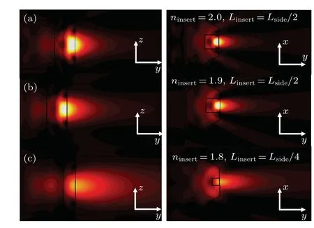
Fig. 7. Contours of power flow scattered by (a) the first selected scatterer with ninsert =2 and Linsert =Lside/2, (b) the second selected scatterer with ninsert =1.9 and Linsert =Lside/2, and (c) the third selected scatterer with ninsert = 1.8 and Linsert = Lside/4 on yz-plane (left column) and xy-plane(right column).
According to the ray optics,the beam astigmatism is determined mainly by the dimension of the field of view. In respect to the scatterer system considered here,it is determined mainly by the dimensions of the scatterer projected onto theyz-andxy-planes because both determine the beam size. This means that one can adopt the following measures to reduce the astigmatism effect. One is to reduce the whole size of the scatterer and/or the differences between the dimensions of its projection onto theyz-andxy-planes,and the other is to adopt an anisotropic scatterer with a graded refractive index.Specifically speaking,the refractive index increases with the distance from the center of the hexgonon increasing,i.e., the farther from the center it is,the larger the refractive index is.
3.3. Characteristics of microjet generated by optimized scatterer at harmonic frequencies
Aiming at the optimized scatterer, we next investigate the effects of harmonic frequencies on features of the microjet generated. The characteristic parameters of microjets generated by the optimized scatterer at the fundamental(f0=35 GHz,λ0=8.57 mm),second(f1=2f0,λ1=λ0/2)and third frequency (f2=3f0,λ2=λ0/3) are shown in Table 3. It is seen that the focal length is-0.066λ0,-0.026λ0,and-0.015λ0, the power enhancement is 28.5, 39.4, 30.1,and the FWHM is 0.262λ0,0.140λ0,0.084λ0,respectively. In three cases, the power enhancement is strong (>28), the FL is nearly zero, and the FWHM is very narrow (<0.265λ0).All the microjets generated at harmonic frequencies have better features than the microjets generated by cuboid.[10,11]The power distributions along theyaxis andxaxis are shown in Figs. 8(a) and 8(b), respectively. As can be observed,the strongest intensity of microjet is obtained at the second harmonic frequency, with a power enhancement~39.4. In Fig. 8(b), we obtain the power distribution curve normalized by this maximum intensity among all three cases,and find that the microjets generated at the second and third harmonic frequency still show good shapes. In practical applications, it provides more flexibility in choosing light wavelength.
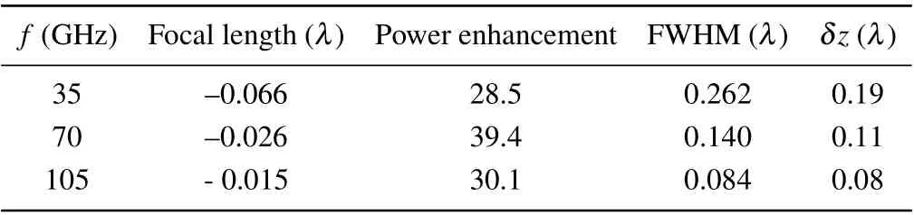
Table 3. Characteristics of microjet generated by optimized double-layer scatterer formed by outer hexagonal prism (ninsert =1.41, Lside =L) and inner cuboid(ninsert=2,Linsert=Lside/2)at harmonic frequencies.
Similarly,we study the features of microjet generated by the second selected double-layer scatterer formed by an outer hexagonal prism(ninsert=1.41,Lside=L)and an inner cuboid(ninsert=1.9,Linsert=Lside/2). The features and power distribution alongyaxis andxaxis of the microjet are shown in Table 4, Figs. 8(c) and 8(d). The second selected scatterer also has good multifrequency focusing properties,with strong power enhancement (25, 33.4, 18), near-zero FL (~0) and narrow FWHM(<0.29λ)at harmonic frequencies.

Fig.8. Power distributions of microjets generated by optimized scatterer along(a)y axis and(b)x axis;power distributions of microjets generated by the second selected scatterer along(c)y axis and(d)x axis at harmonic frequencies.
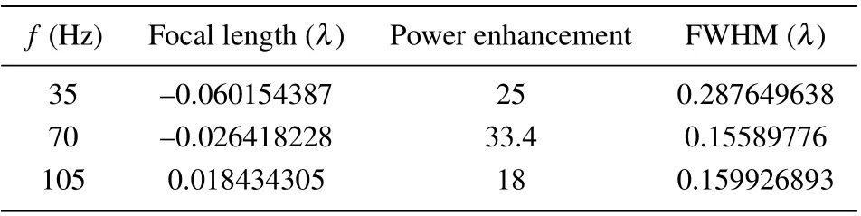
Table 4. Characteristics of microjet generated by the second selected scatterer formed by outer hexagonal prism and inner cuboid (ninsert =1.9,Linsert=Lside/2).
3.4. Interaction between Au spheres and microjet
We also study the effect of an Au sphere present in the microjet on the power distribution. As mentioned in Subsubsection 3.2.2,we place a gold sphere(σAu=4.561×10⁷S/m)into the microjet generated by double-layer scatterer composed of an outer hexagonal prism(nside=1.4,Lside=5 μm,λ=500 nm) and an interior cuboid (ninsert=1.3,Linsert=Lside). The inner cuboid has a smaller refractive index than that of the outer prism,which acts as a buffer layer and makes scatterer generate a microjet with a relatively long focal length and a relatively slow intensity decay. This provides enough room to place Au sphere of different size in the microjet.
Figure 9(a)shows the contours of power flow scattered by the double-layer scatterer,with Au spheres of different diameters (dAu=0.02λ, 0.08λ, 0.14λ, 0.2λ, and 0.26λ) present separately in the center of the microjet. Figures 9(b)and 9(d)give the power distribution along theyaxis andxaxis, respectively. Comparing with the microjet in the case of no Au sphere present, the power distribution curve in Fig. 9 shows the following features. Firstly,the power has a sharp increase at the position of Au sphere edge denoted as the red circle in Fig. 9(c). WhendAu=0.02λ, 0.04λ, 0.06λ, and 0.08λ, the size of metal particle is much smaller than wavelength. For the case ofdAu=0.02λ, since the radius is only one percent of the wavelength, a localized surface plasmon is observed at the interface between Au sphere and air medium. WhendAu>0.14λ, this phenomenon gradually disappears. It can be explained as the fact that the extinction spectrum of the localized surface plasmon is red-shifted with the increase of the particle size.[12-14]It means that the resonance wavelength increases with the increase of Au sphere’s diameter. Thus, in the case of a fixed wavelength and an increasing Au spherical diameter,the localized surface plasmon phenomenon weakens and fades away. Secondly, after a sharp increase, the power declines to 0 quickly due to the metal absorption of Au sphere as shown by a spherical dark spot in the microjet in Fig.9(a),and there appear locally sunken phenomena in power distribution curves along theyaxis andxaxis in Figs.9(b)and 9(d).The relationship between the size of dark spot and the diameter of Au sphere is further studied,and the results show that the length of spherical dark spot along thexaxis and theyaxis are close to the diameter of Au sphere, as shown by the red and black fitted lines in Fig.9(e).

Fig.9. (a)Contours of power flow scattered by double-layer scatterer(Lside=5 μm,λ =500 nm,nside=1.4,Linsert=Lside,ninsert=1.3)with Au spheres with different diameters present in the microjet;power distributions along((b),(c))y axis and(d)x axis;(e)fitted line of relation between length of dark spot and diameter of Au sphere.
In addition, we study the effect of an Au sphere present in the microjet generated by quadrangular prism(Lx=Ly=R,λ=R=8.57 mm)on the power distribution. In the case of an Au sphere with different diameters(dAu=0.08λ,0.14λ,0.2λ,0.26λ,and 0.3λ)present in the microjet,a spherical dark spot emerges there due to metal absorption shown in Fig. 10(a).The dark spot is also seen as a locally sunken phenomenon in power distribution curve alongyaxis andxaxis in Figs.10(b)and 10(c),respectively. The lengths of dark spot alongxaxis andyaxis are close to the diameter of Au sphere as shown by the red and the black fitted lines in Fig.10(d).
In the case that Au sphere present in microjets generated by the double-layer hexagonal scatterer (λ= 500 nm,dAu<0.1λ), there occurs localized surface plasmon resonance phenomenon at the interface between Au sphere and air medium. Since the features of plasma are greatly affected by the properties of the medium,the phenomenon can be used for sensing the complex environmental medium.[15]In the case of quadrangular prism (λ=RanddAu>0.08λ), the localized surface plasmon does not emerge because the size of Au sphere is not matched with the wavelength. However, the spherical dark spot in microjet due to metal absorption exists in both cases. Since the length of dark spot has an approximately linear relation with the diameter of Au sphere,the feature can be used to measure the size of a metallic particle.
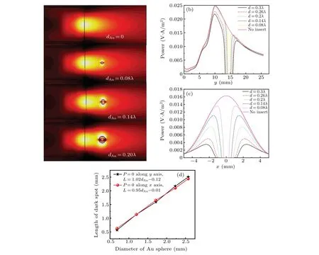
Fig. 10. (a) Contours of power flow scattered by cuboid (Lx =Ly =R, λ =R) with Au spheres of different diameters immersed in; power distribution along((b),(c))y axis,and(d)x axis;(e)fitted line of the relation between size of the dark spot and diameter of Au sphere.
4. Conclusions
We have demonstrated power distribution characteristics of photonic microjet generated by scatterers with different shapes, including triangular, quadrangular, hexagonal, octagonal prisms, cylinder, and double-layer hexagonal scatterers.The demonstration focuses on the effects of the refractive index, size, and shape of the inner layer of the double-layer scatterer on the power distribution of microjet generated. The demonstration also focuses on effects of harmonic frequencies and an Au sphere present in the microjet. Some conclusions can be made below.
(i)Microjet is formed by overlapping the light waves scattered by the micro-particle in nature.It can be simply modeled as the focusing of scattered light waves by a polygonal prism lens,and the polygonal prism functions as a lens.
(ii) As the scatterer is changed from quadrangular to hexagonal prism,the power of microjet increases significantly.As the edge number of bottom face of polygonal scatterer further increases from the hexagonal prism,the increase of power then slows down. Instead,the FWHM continuously increases with the edge number of the polygonal scatterer increasing.Thus, the hexagonal prism is a compromised choice. Based on the hexagonal prism, a double-layer scatterer is proposed to improve the features of microjet generated.
(iii)Both the refractive index and the size of inner layer of double-layer scatterer are important factors influencing microjet features.As the refractive index and size increase,the focal length becomes short and the power enhancement increases.
(iv) The optimized double-layer scatterer is formed by a hexagonal prism withLside=R,nside=1.4 as the outer layer,and a cuboid withLinsert=Lside/2,ninsert=2 as the inner layer.It generates a microjet with a strong power enhancement of~28.5,a narrow FWHM of~0.262λand a nearly zero FL.
(v)A study on the effect of harmonic frequencies on the features of microjet shows that the microjet generated at the second harmonic frequency 2f0has the largest power enhancement,while that generated at the third harmonic frequency 3f0has the narrowest FWHM. The multifrequency focusing microjets all show good shapes.
(vi) In case of an Au sphere present in the microjet, a spherical dark spot emerges there due to metal absorption.The length of the dark spot is very close to the diameter of Au sphere. In the case that the size of gold sphere is much smaller than the wavelength(λ=500 nm),a localized surface plasmon resonance phenomenon is observed at the interface between Au sphere and air medium.
Acknowledgement
Project supported by the National Natural Science Foundation of China(Grant No.61875148).
猜你喜欢
环球时报(2019-03-14)2019-03-14
环球时报(2019-02-21)2019-02-21
环球时报(2017-04-10)2017-04-10
环球时报(2016-11-01)2016-11-01
环球时报(2013-01-08)2013-01-08
环球时报(2009-11-23)2009-11-23

- Chinese Physics B的其它文章
- Measurements of the 107Ag neutron capture cross sections with pulse height weighting technique at the CSNS Back-n facility
- Measuring Loschmidt echo via Floquet engineering in superconducting circuits
- Electronic structure and spin-orbit coupling in ternary transition metal chalcogenides Cu2TlX2(X =Se,Te)
- Characterization of the N-polar GaN film grown on C-plane sapphire and misoriented C-plane sapphire substrates by MOCVD
- Review on typical applications and computational optimizations based on semiclassical methods in strong-field physics
- Quantum partial least squares regression algorithm for multiple correlation problem