
A low-cost invasive microwave ablation antenna with a directional heating pattern
2022-03-12 07:49ZhangWen文章XianQiLin林先其ChenNanLi李晨楠andYuLuFan樊钰璐
Chinese Physics B 2022年3期
关键词:文章
Zhang Wen(文章) Xian-Qi Lin(林先其) Chen-Nan Li(李晨楠) and Yu-Lu Fan(樊钰璐)
1School of Electronic Science and Engineering,University of Electronic Science and Technology of China,Chengdu 611731,China
2The Yangtze Delta Region Institute(Huzhou),University of Electronic Science and Technology of China,Huzhou 313001,China
Keywords: cancer treatment,microwave ablation(MWA)antenna,thermal therapy,directional heating pattern
1. Introduction
Cancer is currently one of the most serious threats to human health.[1]Researchers are still exploring effective treatments for cancer.[2]In recent years, microwave ablation(MWA)technology,as an important means of treating tumors,has gradually attracted the attention of researchers.[3]The microwave ablation antenna is one of the most critical devices,which has the ability to radiate high-power microwave energy to tumor tissue, heating it up rapidly in order to kill it.[4,5]Microwave ablation antennas can be divided into non-invasive microwave ablation antennas and invasive microwave ablation antennas. The non-invasive microwave ablation antenna is generally an array of antennas outside the body, which focus electromagnetic energy on and kill tumor cells in the human body. The invasive microwave ablation antenna is generally a slender single antenna. It can be directly inserted into the tumor with the help of ultrasound or CT imaging and transmit electromagnetic energy to the surrounding tumor cells. At present,the invasive microwave ablation antenna is used more clinically because of its advantages,such as low cost and simple principle. The ablation shape of the invasive MWA antenna should correspond to the shape of the tumor to avoid tumor recurrence or unnecessary damage to healthy tissues.In addition, the size of the cross-sectional area and the local ablation pattern are important features of the invasive MWA antenna. The small cross-sectional area can help achieve a minimally invasive therapy,and the local ablation pattern can protect healthy tissue from unwanted harm.[6]
Since many tumors are spherical,the ablation area of the MWA antenna is usually designed to be spherical. However,in some cases, the MWA antenna may be difficult to insert safely into the tumor center or the shape of some tumors may be asymmetrical.[7-9]In these circumstances, an ablation antenna with directional ablation capability might be a better choice for ablation surgery. In Ref.[7],an antenna with a directional ablation pattern is designed. A coaxial monopole is placed inside an external stainless-steel tube,the end of which is designed as a hemicylindrical metallic reflector to guarantee unidirectional propagation of electromagnetic energy. Then,the whole structure is put inside a polyimide catheter, and water is circulated between the stainless-steel tube and polyimide catheter to achieve impedance matching and heat dissipation. Nevertheless, there are problems with low efficiency and the large cross-sectional size. To address these problems,a coax-fed monopole,which can produce an asymmetric ablation zone,is proposed in Ref.[8]without water circulation and an external stainless-steel tube. The key structures forming the asymmetric ablation zone are the reflector,which extends from the outer conductor of the coaxial line and the semicylindrical slot etched on the outer conductor of the coaxial line.An impedance matching network is designed on coaxial line.The antenna can produce a directional ablation pattern at high efficiency and a small cross-sectional size. However, these antennas[7,8]are processed on traditional round coaxial cable,the structure of which is complicated and the processing technology is immature. In addition,the design freedom of round coaxial cable is limited by its structure.
In this paper,a low-cost microwave ablation(MWA)antenna with a directional heating pattern is proposed.The structure of the antenna and the simulation results are explained in Section 2. Then, an ablation experiment is performed in porcine liver and the experimental results are given in Section 3. Finally, the conclusion is discussed in Section 4. The antenna based on substrate integrated coaxial line(SICL)can produce a large directional ablation zone with a small crosssectional area,and can be mass-produced by a mature and inexpensive PCB processing technology.
2. Antenna design and simulation
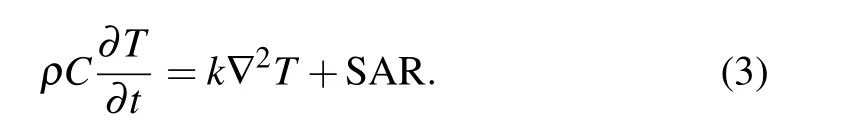
For the design of an invasive microwave ablation antenna,its working environment is very important. Many studies have reported usingex vivoliver and egg white to simulate the working environment of microwave ablation antennas.[10,11]Although the ablation experiment in the egg white is beneficial for observing changes in the ablation area in real time, it also has the disadvantage of fluidity. This paper uses porcine liver as an ablation material for research. The dielectric properties and thermal properties of porcine liver can be found in Ref. [12]. For the design of an invasive microwave ablation antenna, attention should be paid to the electromagnetic properties of the antenna, including the reflection coefficient(S11) and specific absorption rate (SAR) distribution. During the microwave ablation process, the continuous deposition of electromagnetic energy causes the tissue temperature to rise, and the energy deposition amount is defined by the SAR. The reflection coefficient(S11)of the antenna indicates how much electromagnetic energy can enter the antenna,and the SAR distribution of the antenna can initially predict the ablation shape of the antenna. The electromagnetic properties of the antenna can be obtained by full-wave simulation software,which is based on the finite element method. The reflection coefficient can be calculated by Maxwell equations, and then the SAR is calculated using the following formula:[12]whereCis the specific heat capacity of the tissue,Tis the tissue temperature,kis the thermal conductivity of the tissue,ρbis the blood density,Cbis the specific heat capacity of the blood,v=v+aTis the blood perfusion,Qmis the heat generated by metabolism andQextis the external source. In this paper,since there is no blood perfusion and metabolism in the isolated liver,ρbCbvb(Tb-T)andQmcan be omitted. Due to the increase in temperature of the tissue caused by the deposition of electromagnetic energy,the external heat sourceQextis equal to the SAR. Therefore,formula(2)can be simplified to the following:
2.1. Antenna design
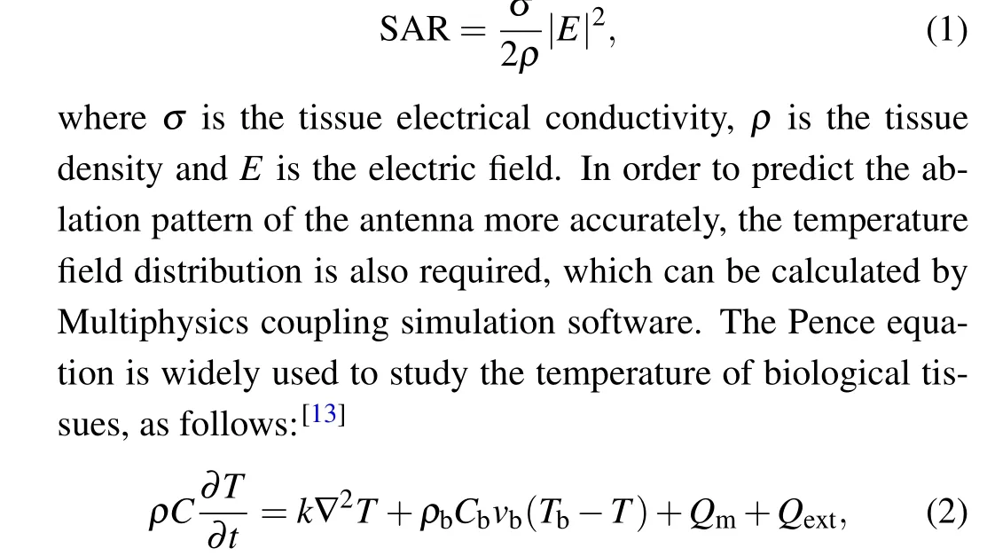
As shown in Fig.1,the proposed antenna is designed using the PCB process technology on three-layer substrates with two dielectric layers (FR4,εr= 4.8, tanδ= 0.02, 0.2 mm in thickness) and a bonding layer (FR4,εr= 4.8, tanδ=0.02,0.254 mm in thickness). All parameters are listed in Table 1. The proposed antenna is fed by the SICL,and the SICL is fed by the coplanar waveguide (CPW). Figure 2(a) shows the structure of the SICL inxoyplane and figure 2(b) shows the CPW-to-SICL transition inzoyplane. The inner conductor of the SICL is situated between the dielectric layer and bonding layer. The cross-sectional area of the SICL is designed to be 3 mm×0.7 mm, and the characteristic impedance of the SICL can be adjusted by the size of the inner conductor of the SICL.A fast estimation method of characteristic impedance of the SICL can be obtained in Ref.[12]. If the input impedance of the antenna is obtained, this method and the Smith chart can be used to perform fast matching,avoiding low-efficiency optimization in the full-wave simulation software.former structures with characteristic impedance of 52.6 Ω and 33 Ω, respectively. A 10-mm-long CPW with characteristic impedance of 50 Ω is cascaded with an 8.5-mm-long SICL with characteristic impedance of 50 Ω to solder the SMA connector. The CPW and inner conductor of the SICL are connected through a metallized via,as shown in Fig.2(b).

Table 1. The dimension of the antenna.

Fig.1. Geometry of the proposed directional ablation antenna.
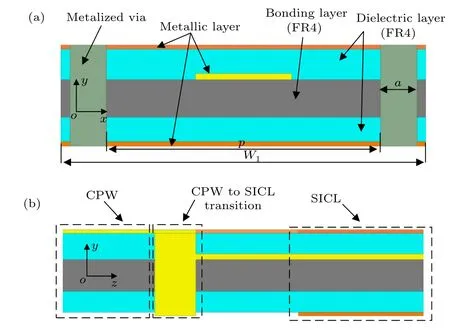
Fig.2. The detailed geometry of the antenna. (a)The geometry of the SICL in xoy plane. (b)CPW to SICL transition in zoy plane.

Fig. 4. Simulated SAR distribution around the antenna in porcine liver at 2.45 GHz in yoz plane. (a) The monopole without reflector. (b) The monopole with reflector.
Fig.3. The geometry structure of monopole and matching. (a)The geometry of the monopole and the reflector in xoz plane. (b)The geometry of the impedance matching network in xoz plane.
The monopole located between the dielectric layer and bonding layer is fed by the SICL, and connected to the inner conductor of the SICL, as illustrated in Fig. 3(a). The length of the monopole is chosen to be 20 mm (about 0.37 wavelength in FR4). At this length, the antenna can achieve good single-sided radiation performance. The optimized width of the monopole affecting the input impedance is designed to be 2 mm. The SAR distribution of the monopole without a reflector is omnidirectional, as shown in Fig. 4(a). Since the current on the inner surface of the outer conductor is not balanced,it will be reflected to the outer surface when flowing to the antenna, leading to the long “tail” phenomenon. In order to generate a directional ablation pattern, the outer conductor of the SICL is extended to form a reflector with a length of 22 mm, slightly longer than the monopole. Figure 5 shows that the current on the outer surface of the outer conductor is small and the current on the monopole is balanced by the current on the reflector.[7]Therefore,the long“tail”phenomenon will not occur on the insertion path of the antenna.[11]However, the monopole is close to the reflector, leading to a low input impedance of the antenna with a value of 5.63+j33.4 Ω at 2.45 GHz.As shown in Fig.3(b),three portions of the SICL with different impedance performs impedance matching The process is shown in Fig. 6 on the Smith chart. A 5.1-mmlong SICL with characteristic impedance of 20 Ω changes the input impedance to 260.93-j6.4 Ω at 2.45 GHz.Then,the input impedance is matched to 50 Ω by two quarter-wave trans-

Fig. 5. Antenna current distribution. (a) The current vector distribution on the monopole at 2.45 GHz. (b)The current distribution on the top surface of the outer conductor of SICL at 2.45 GHz.

Fig.6. Impedance matching process of the monopole on the Smith chart.
If the proposed antenna works within the-10 dB impedance bandwidth, the shape of the SAR will not change drastically with frequency. However, if the impedance of the antenna is seriously mismatched,the SAR of the antenna will decrease overall due to the energy reflection.
If the size of the inner conductor of the SICL is adjusted to maintain the same characteristic impedance, the crosssectional area of the antenna can be further reduced, despite the increased cost of manufacturing.
2.2. Simulated results of the antenna
The antenna operating in porcine liver tissue is modeled in ANSYS HFSS for the reflection coefficient. Figure 7 depicts the simulatedS11performance of the antenna in porcine liver,and theS11is lower than-20 dB at 2.45 GHz.Due to the use of multiple quarter-wave transformer structures,the bandwidth of the antenna is relatively narrow at 3.6%. A further study has been made of the size parameters of the monopole,as shown in Fig.8. When the width of the monopole changes,its resonant frequency will change slightly, and the matching degree will also change. When the length of the monopole changes, its resonance frequency will change to a greater extent, and its matching degree will also change, correspondingly.
Results in the thermal field,which can predict the ablation pattern of the antenna,should also be taken into consideration.The antenna is simulated in CST Microwave Studio for SAR distribution. Figure 4(b) shows the SAR distribution around the proposed antenna in the porcine liver at 2.45 GHz. It is observed that due to the presence of the reflector,the electromagnetic energy is highly concentrated in the positivez-axis direction. In addition,the SAR distribution is local and no obvious“tail”is found around the SICL.In order to predict the ablation pattern of the antenna more accurately, the antenna is then modeled and simulated in COMSOL Multiphysics for transient thermal simulation. After being placed inside the FEP heat shrink tube, the antenna is inserted into the porcine liver and then placed in the air for simulation. Initially, the temperature of the porcine liver is set to an ambient temperature of 25°C. And the temperature of the air cavity wall is always set to 25°C.The electromagnetic power level used for temperature simulation is 10 W. The simulated ablation zone in the porcine liver is shown in Fig.9 after 10 min.The median temperature of the congestion zone,60°C isotherm,is chosen to be the boundary of the ablation zone.[14]The ablation shape around the antenna is highly similar to the SAR distribution,which is local and directional. The 60°C temperature contour cannot be found around the SICL.Because of the thermal conductivity of porcine liver, the heat is partly conducted to the back of the reflector, weakening slightly the directionality of the ablation pattern. The directivity ratio(DR)is used to quantify the directivity of the antenna,which can be calculated using the following formula:[8]
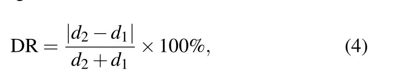
whered1andd2are defined as the distance between the edge of the ablation zone and the center of the antenna, as shown in Fig. 9. Based on this simulation result, the value ofd1is 13.8 mm, the value ofd2is 4.4 mm and the value of DR calculated using formula(4)is 51.6%.

Fig. 7. Simulated and measured S11 of the MWA antenna with directional ablation pattern.
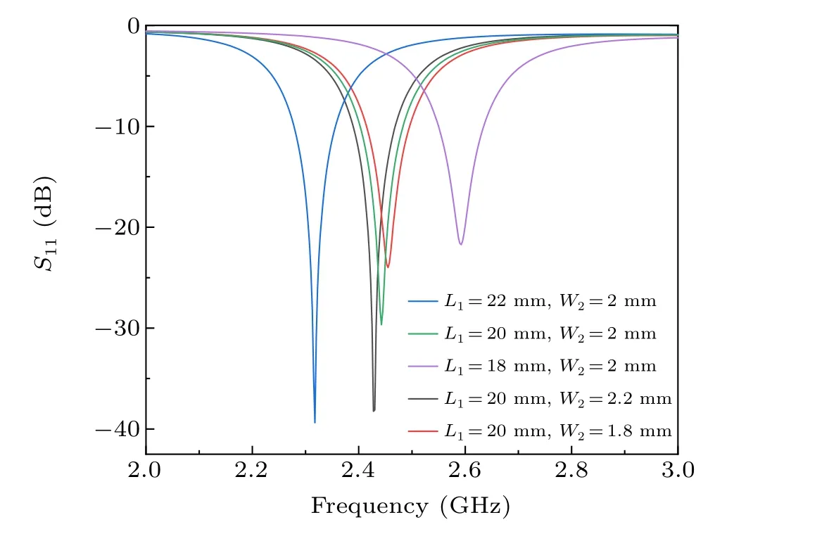
Fig.8. Simulated S11 of the MWA antenna with different monopole sizes.

Fig.9.The ablation area of porcine liver obtained by simulation in COMSOL at a power level of 10 W for 10 min.
3. MWA experimental results
In order to verify the validity of the design, a prototype of the proposed antenna is fabricated by PCB process technology. A photograph of the fabricated prototype is shown in Fig.10. The whole structure of the antenna (except CPW)is put into an FEP heat shrink tube with a thickness of 0.2 mm and radius of 3 mm to prevent the metal from being corroded.A heat gun is used to blow air at 220°C against the heat shrink tube, making it shrink to be as close to the antenna as possible. Then, the thickness of the heat shrink tube changes to about 0.35 mm measured using a Vernier caliper. Before the ablation experiment,the antenna inserted into the porcine liver is measured forS11using a vector network analyzer (Agilent 5244A)and the measured result is compared with simulation,as shown in Fig.7. The center frequency of the measured result is around 2.43 GHz and the simulated one is 2.45 GHz.The difference can be attributed to the size difference between the simulation model and the fabricated one. Since the dielectric parameters of porcine liver in simulation are measured at around 2.45 GHz,this leads to the difference between the simulated and measured results at other frequencies.
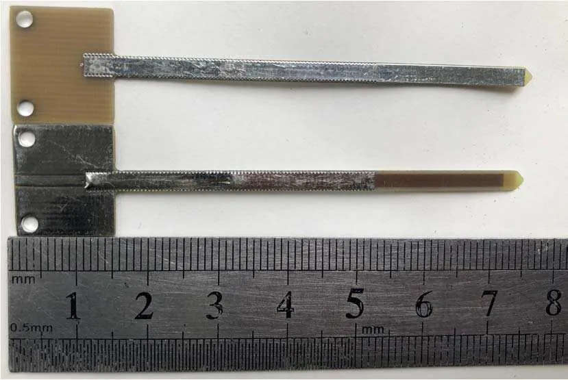
Fig.10.The photograph of the directional ablation antenna prototype at front and back view.
The ablation experiment at power of 10 W for 10 min is performed in porcine liver. A continuous wave with a frequency of 2.45 GHz is generated by a microwave source. The experiment is repeated four times. Due to the bandwidth of the antenna being narrow,the matching degree may deteriorate rapidly when the working environment of the antenna changes.Therefore, the power reflected from the antenna needs to be monitored to observe the changes from the impedance matching of the antenna in the ablation process. At the beginning of the experiments, the reflected power is less than 0.5 W,but it gradually decreases to no more than 0.2 W as the experiment progresses. The reason may be that during the ablation process, the temperature of the porcine liver gradually increases,which leads to changes in the dielectric parameters of the porcine liver.
The ablated porcine livers are dissected after the experiment and figure 11 presents one of the ablation zones inyozplane. The average size of the ablation zone is approximately 11.675 mm×29.4 mm. Consistent with the simulation results in COMSOL, a small ablation area is formed behind the reflector,which has an average size of approximately 4.3 mm×17.3 mm.The undesired ablation area on the back of the reflector may cause the patient to bear additional surgical burden.However,this area is very small for an overall ablation area,and this additional burden can basically be ignored. The measured DR in this experimental result is 46.17%, which is slightly lower than the simulation result. The reason may be that the reflector is a good heat conductor,and it also emits a small amount of heat to the back of the reflector. The value of DR indicates that the antenna has a high directional ablation capability. Furthermore,no obvious ablation zone is observed along the insertion path of the antenna on the side of the reflector, while a small ablation zone of the ablation area appears along the insertion path of the antenna on the opposite side.This is due to the heat conduction effect instead of the “tail”phenomenon, otherwise the ablation area will appear evenly on both sides of the feed line.

Fig.11. The ablation area of the directional ablation antenna in porcine liver after experiment.
4. Conclusion
In this paper, we present a low-cost antenna for directional ablation. This design exploits a monopole structure with a reflector on the end of the SICL to form a local directional ablation pattern. Impedance matching is achieved through three portions of SICL with different impedance. In an ablation experiment at power of 10 W for 10 min in porcine liver,the antenna demonstrates its capability of directional ablation. Compared to other directional ablation antennas reported in Refs.[7,8], the cross-sectional area of the proposed antenna is smaller,and the manufacturing process is more mature. This demonstrates the potential of the proposed antenna for application in the directional ablation field.
Acknowledgments
Project supported by the National Natural Science Foundation of China (Grant No. U1966201) and the Fundamental Research Funds for the Central Universities,China(Grant No.A03019023801224).
猜你喜欢
华人时刊(2022年5期)2022-06-05
学生天地(2020年25期)2020-06-01
生物骨科材料与临床研究(2020年1期)2020-03-04
传媒评论(2019年7期)2019-10-10
学生天地(2019年33期)2019-08-25
小学生学习指导(中年级)(2018年4期)2018-09-06
小学生作文(中高年级适用)(2018年4期)2018-05-14
现代企业(2015年6期)2015-02-28
小雪花·小学生快乐作文(2009年4期)2009-04-27
中学生英语·外语教学与研究(2008年7期)2008-12-19

- Chinese Physics B的其它文章
- Measurements of the 107Ag neutron capture cross sections with pulse height weighting technique at the CSNS Back-n facility
- Measuring Loschmidt echo via Floquet engineering in superconducting circuits
- Electronic structure and spin-orbit coupling in ternary transition metal chalcogenides Cu2TlX2(X =Se,Te)
- Characterization of the N-polar GaN film grown on C-plane sapphire and misoriented C-plane sapphire substrates by MOCVD
- Review on typical applications and computational optimizations based on semiclassical methods in strong-field physics
- Quantum partial least squares regression algorithm for multiple correlation problem