
Study of post-arc residual plasma dissipation process of vacuum circuit breakers based on a 2D particle-in-cell model
2022-05-05 01:49YongpengMO莫永鹏ZongqianSHI史宗谦andShenliJIA贾申利
Plasma Science and Technology 2022年4期
Yongpeng MO (莫永鹏), Zongqian SHI (史宗谦)and Shenli JIA (贾申利)
State Key Laboratory of Electrical Insulation and Power Equipment, Xi’an Jiaotong University, Xi’an 710049, People’s Republic of China
Abstract In order to get an insight into residual plasma radial motion during the post-arc stage, a twodimensional(2D)cylindrical particle-in-cell(PIC)model is developed.Firstly,influences of a virtual boundary condition on the residual plasma motion are studied.For purpose of validating this 2D cylindrical particle-in-cell model, a comparison between one-dimensional particle-in-cell model is also presented in this paper.Then a study about the influences of the rising rate of transient recovery voltage on the residual plasma radial motion is presented on the basis of the 2D PIC model.
Keywords: vacuum circuit breakers, residual plasma dissipation, particle-in-cell simulation
1.Introduction
The post-arc dielectric recovery process has decisive influences on a successful current interruption in a vacuum circuit breaker.Therefore, the post-arc dielectric recovery process causes more and more concern.The post-arc dielectric recovery process begins at the moment when the current flowing a vacuum circuit breaker decreases to zero and it will last till the moment when the interelectrode region recoveries its dielectric strength.
During the arcing stage, arc plasma, metal vapor and droplets are generated by the erosion of vacuum arc.When the interruption current decreases to zero,the residual plasma,metal vapor and droplets still exist between the contacts [1].After current zero, a negative rapid increasing transient recovery voltage generated by the external circuit will be applied to the contacts.Then the ions and electrons are separated from each other.The electrons are driven to the post-arc anode quickly while the heavier ions stay behind.Then an ion sheath, the socalled post-arc sheath,forms and then it will develop toward the post-arc anode.During the above residual plasma dissipation process, the post-arc current forms when the electrons and ions are absorbed.The residual plasma dissipation process, the beginning of post-arc dielectric recovery process, is very important for a successful current interruption process in a vacuum circuit breaker.Therefore, it is of great significance to study this process.
The continuous transition model(CTM)which is developed in the 1970s, has been being widely used in post-arc sheath simulations of vacuum circuit breakers [2].However, CTM is not very self-consistent in dealing with the bounded plasma because the derivation of CTM is based on a semi-infinite plasma.In recent years, more and more refined models are developed to study the residual plasma dissipation process.Sarrailh et al [3-5] studied the effects of transient recovery voltage and residual plasma density on the post-arc sheath expansion with a one-dimensional hybrid Maxwell-Boltzmann(hybrid-MB)model.In addition, the effects of contact evaporation and secondary emissions were also studied by a onedimensional hybrid-MB model combining with the Monte-Carlo collision (MCC)method.
The one-dimensional hybrid-MB model takes less computing time but not so self-consistent as the full particle-in-cell(PIC)model because both ions and electrons in a full PIC model are treated as macro particles.Some researchers then adopted the PIC models to study the microphysical mechanism of post-arc dielectric recovery process [6-9].It should be noted that the studies with 1D PIC models only can focus on the residual plasma axial motion.
To gain further understanding of the residual plasma dissipation process, Sarrailh et al [10] developed a twodimensional hybrid-MB model to study the influence of vacuum interrupter shield polarity on the post-arc residual plasma dissipation process.Takahashi et al [11] investigated the influence of the residual plasma on the post-arc breakdown process in a 168 kV/25 kA vacuum interrupter with a 2D PIC-MCC model.Wang [12] studied the influence of metal vapor on the post-arc breakdown process after current zero by a 2D PIC-MCC model.However, a 2D PIC-MCC model based on the full size of commercial vacuum interrupter is time-consuming.In order to reduce the computing time, an open wall boundary condition (zero axial electric field and specular reflection of ions)was adopted in the 2D hybrid-MB model[10].Due to this,the simulation domain of the 2D hybrid-MB model can be reduced to a much smaller size than the commercial vacuum interrupters.It also should be noted that some charged particles would fly to the virtual boundary according to the simulations in [10].Otherwise,these charged particles might also affect the potential distribution near the virtual boundary.Obviously, a proper boundary condition for PIC simulation will benefit the further study of residual plasma dissipation process.However, there is still few studies about the effects of boundary condition on the residual plasma dissipation process.What is more, the residual plasma radial motion and its effects on the residual plasma dissipation process still remain unclear.
In order to get a further understanding of the effects of boundary condition and the residual plasma radial motion on the residual plasma dissipation process,a 2D PIC model with cylindrical coordinate system is developed in this work due to the axisymmetric characteristic of vacuum interrupter based on an extension of our previous work[13].Then an evaluation of this 2D PIC model is presented.Besides,because the transient recovery voltage is important to the residual plasma dissipation process,the influences of rising rate of transient recovery voltage on the residual plasma radial motion are also simulated and discussed.
2.Model introduction
In this work, a 2D PIC model with the cylindrical coordinate r-z system, which does not take the magnetic field into consideration, is developed by the software VSim.Figure 1 presents a sketch map of cells with indices j, k.The Δr and Δz in directions r and z are uniform, respectively.With Gauss’ law, the charges for the volume shown by dash lines centered on (rj, zk)can be obtained
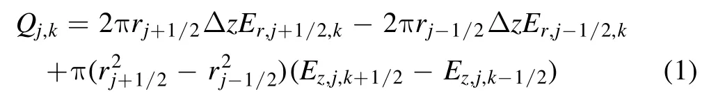
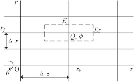
Figure 1.The sketch map of cells with indices j, k.
WhereQj,kis the charge,Er,j,kis the electric filed in r direction, andEz,j,kis the electric filed in r direction.
At the origin (j=0),

Withρj,k=Q j,k/Vj,kandVj,k= π (Δr2)jΔztaking into consideration, the charge density is

The Er,j,kand Ez,j,kcan be written as

Then a five points finite-difference form of Poisson’s equation can be obtained

After that, the instantaneous position of electrons and ions can be solved by Newton’s law.

Where (r, z)are the charged particle position, qeand meare the charge and mass respectively for electrons, and qiand miare those for positive ions, and (Er, Ez)are the electric field strengths at(r,z).More theory and numerical approach of PIC simulation can be founded in [14].
Figure 2 presents the structure of a vacuum interrupter and the schematic diagram of the 2D PIC model.The computing time increases rapidly with the increase of computing area.In an ideal simulation, the 2D PIC model should be based on a full-size vacuum interrupter as shown in the upper picture of figure 2.However,this will cost a lot of computing time,which is not conducive to the further study of residual plasma dissipation process.

Figure 2.Structure of the vacuum interrupter (upper)and sketch diagram of the 2D PIC model (bottom).
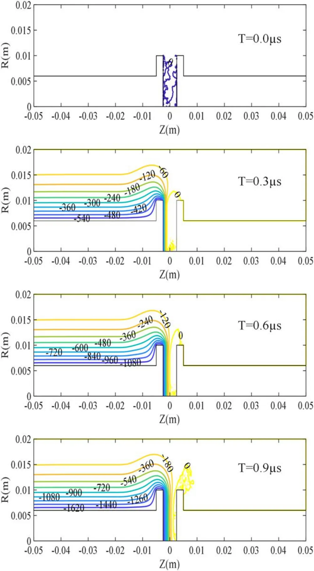
Figure 3.The distribution of the equipotential lines with Lc = 0.100 m.
The residual plasma dissipation process is the major concern during the post-arc dielectric recovery process.Decreasing the computing area with a virtual boundary instead of a physical boundary is important for further study.Therefore, the 2D PIC model (bottom)only focuses on the shaded part of a vacuum interrupter (upper)as shown in figure 2.The radius of two contacts Lcris 0.01 m.The shield is assumed to be 0.02 m away from the contact axis (R direction).The contact plate thickness Lptis 0.0025 m.The contact gap between the post-arc cathode and post-arc anode is 0.005 m and the conductive rod radius Lrris 0.006 m.Lcis the length between the right boundary and the left boundary(Z direction).
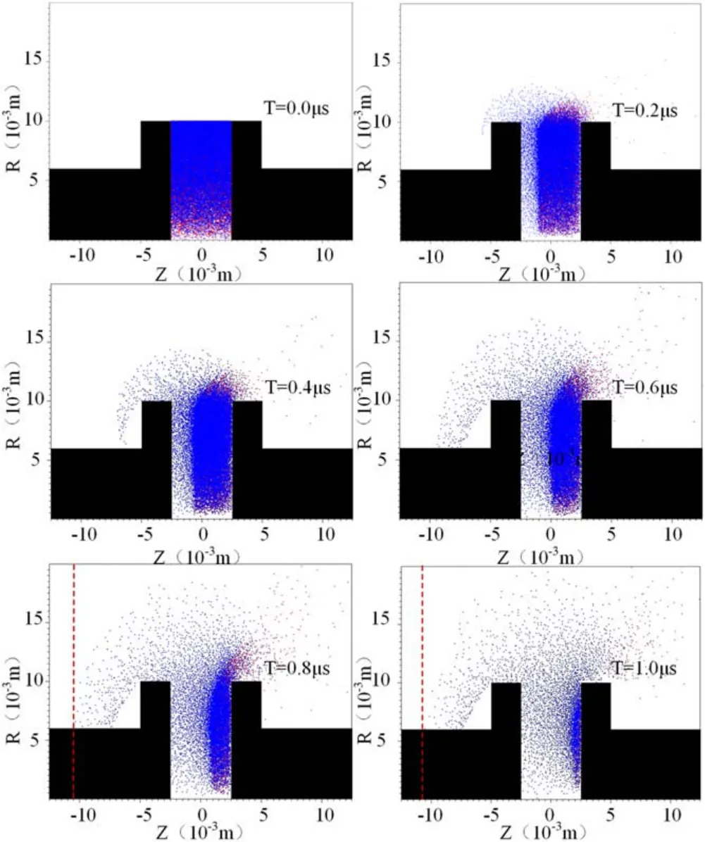
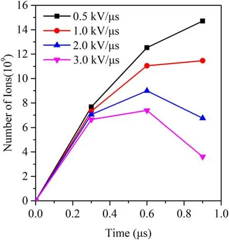
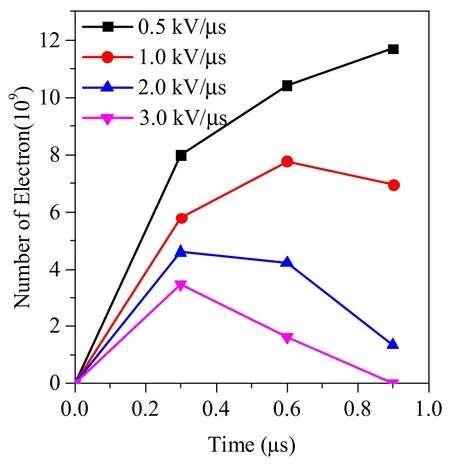
Because the vacuum arc mainly burns in the interelectrode region, we assume that the residual plasma mainly exists in the interelectrode region at current zero.The interelectrode region represents the region where R < 0.01 m and −0.0025 m Because the electrons move to post-arc anode quickly and the heavier ions are left behind, an ion sheath forms in front of post-arc cathode and develops to post-arc anode as shown in figure 2.For reducing computation time, the collisions between charged particles, secondary electrons and emissions from both contact and shield,are still not taken into consideration in this model.When the electrons or ions arrive at the contacts, the conductive rod or the shield, they are removed from the 2D PIC model. Two virtual boundaries,the left boundary and right boundary as shown in the bottom picture of figure 2,are needed for the 2D PIC model.In a vacuum interrupter, the potential distribution is closely related to the contact plate structure, the residual plasma and the metal shield.The metal shield is parallel to conductive rod of contacts except the parts near two ends.For a 12 kV/1.6 kA commercial vacuum interrupter, the distance between two ends is about 0.2 m.The length of commercial vacuum interrupters will be longer for a higher voltage level. When two boundaries are relatively far away from the contact plates,the residual plasma in the interelectrode region can hardly fly to the left boundary or right boundary.Under such a condition,the residual plasma motion will show small effects on the potential distribution near the left boundary and the right boundary.Besides, when two boundaries are relatively far away from contact plates and the ends of metal shield,the structure of contact plates and the irregular ends of metal shield would show relatively small influence on these two boundaries.Therefore, the potential near two boundaries between the conductive rod and metal shield would not change along the direction Z.Because few charged particles will fly to two boundaries, we ignore the reflections and secondary electrons on two boundaries.All charged particles which fly to two boundaries are assumed to be absorbed and removed from simulations. When Lcis 0.100 m, two boundaries are about 0.045 m away from the contact plates and at least 0.04 m away from two ends of the metal shield.The influence of contact plate structure and irregular ends of metal shield on the potential distribution near the left boundary and right boundary is assumed to be small under this condition (about 20 times of the contact gap).According to the above analysis,a boundary condition Ez=0,which means that the electric field strength does not change in direction R, is adopted to the left boundary.Referring to the boundary conditions in [10], the right boundary potential is assumed to be zero,which is equal to post-arc anode potential.The other parameters are introduced in section 2. Figure 3 shows the distribution of equipotential lines with Lc= 0.100 m.The irregular distribution of equipotential lines in the interelectrode region at T = 0.0 μs is mainly caused by the random distribution of limited macro particles.The equipotential lines with different potentials are irregular near the contact plate at T = 0.3 μs.From figure 3 we can see that the equipotential lines between Z = −0.01 m and−0.02 m are irregular and gradually parallel to the contact axis.Figure 3 also shows that the equipotential lines on the left of Z = −0.02 m are almost parallel to the contact axis.From figure 3 we can see that Lccan be further reduced.Then Lc= 0.05 m has been simulated.Figure 4 shows the distribution of equipotential lines with Lc= 0.05 m.From the figure 4 we can see that the equipotential lines on the left of Z = −0.017 m are also parallel to the contact axis after T = 0.3 μs.The equipotential lines between Z = −0.01 m and Z = −0.017 m are gradually parallel to the contact axis.From figures 3 and 4 we can see that the equipotential lines V = 180 V with Lc= 0.050 m and 0.100 m are both placed at R = 0.015 m near the left boundary at T = 0.9 μs.This indicates that the variations of the equipotential lines with Lc= 0.050 m and 0.100 m are similar. Figure 4.The distribution of the equipotential lines Lc = 0.050 m. Figure 5.The distribution of the equipotential lines with Lc = 0.025 m. The simulation results in figures 3 and 4 indicate that Lcseems to be able to be further reduced because the irregularity of equipotential lines mainly occurs in the region between Z = −0.01 m and Z = −0.02 m.Then we carried out another simulation with Lc= 0.025 m.Figure 5 presents the distribution of equipotential lines with Lc=0.025 m.From figures 3 and 4 we can see that not all equipotential lines near Z = −0.0125 m are parallel to the contact axis, especially when R > 0.01 m.Figure 5 shows that all equipotential lines near the left boundary are forced parallel to the contact axis under the effect of the left boundary condition.The equipotential line V = 180 V with Lc= 0.025 m is placed at about R = 0.016 m near the left boundary at T = 0.9 μs.This indicates that there is a small difference between the distribution of equipotential lines with Lc= 0.025 m and Lc= 0.050 m, 0.100 m.Therefore, the left boundary condition shows certain unexpected effects on the residual plasma motion under these three conditions.The left boundary condition might further distort the distribution of equipotential lines and charged particle motion if Lcis further reduced,which may cause more unexpected calculation errors. For the purpose of getting a further study about the influence of left boundary condition, figure 6 presents the residual plasma motion when Lcis 0.025 m.The red ones are electrons and the blue ones are ions.From figure 6 we can see that the macro particles near R = 0 m look sparse.A brief explanation is presented below.The cells of Z and R directions are uniform in the 2D PIC model.The macro particles in a cell represent the total electrons or ions in a ring whose volume increases with radius in the cylindrical coordinate system.This means that the total number of macro particles in a cell increases with the radius.Therefore, the residual plasma between the contact gap of the 2D PIC model is uniform despite macro particles near R = 0 look uneven.However, it should be noted that there are only a small number of macro particles placed near the R = 0 region,which may cause noise when we estimate the plasma density,potential distribution or post-arc sheath thickness.Even so, a possible strategy to deal with this issue is increasing the number of macro particles at the small radii. Figure 6 also shows that both ions and electrons will fly out of the interelectrode region during the residual plasma dissipation process.The ions mainly move toward the postarc cathode and the electrons move toward the post-arc anode under the effect of transient recovery voltage.As a result,most ions and electrons in the interelectrode region are absorbed by the contact surface.Figure 6 also shows that the electrons or ions outside of the interelectrode region can fly to the lateral surface of contacts,the conductive rod or the metal shield and then they are absorbed.From figure 6 we can also see that some electrons could fly to the right boundary after T = 0.6 μs.Figure 6 also indicates that the ions cannot fly to the left boundary under the effect of transient recovery voltage.The ions can fly to the position Z = −0.011 m at T = 0.8 μs and then be absorbed by the conductive rod.However, some electrons can fly to the right boundary after T = 0.6 μs. Figure 6.Residual plasma motion at different moments when Lc = 0.025 m. What is more, the number of ions and electrons flying outside the interelectrode region is also counted for evaluating the influence of the boundary condition quantitatively.The βemeans the proportion of the number of electrons outside the interelectrode region to the number of electrons in the whole simulation domain.The βimeans the proportion of the number of ions outside interelectrode region to the number of ions in the whole simulation domain.Figure 7 presents the proportion βiwith Lc= 0.025 m, 0.050 m and 0.100 m at different moments.Figure 8 presents the proportion βewith Lc= 0.025 m, 0.050 m and 0.100 m at different moments.It can be seen from figure 7 that the boundary condition shows little effect on the ion radial motion when Lcis reduced to 0.025 m.It can also be seen from figure 8 that the boundary condition still shows little influence on the electron radial motion before 0.6 μs.At T = 0.9 μs, more electrons would fly outside the gap with Lc= 0.025 m compared with Lc= 0.050 m and 0.100 m.The βewith Lc= 0.025 m, 0.05 m and 0.1 m are about 10.38%,9.75%and 9.62%at 0.9 μs,respectively.After the calculations follow[βe(Lc= 0.025)−βe(Lc=0.1)]/βe(Lc= 0.1),the βewith Lc= 0.025 m is about 6.5%higher than the βewith Lc=0.050 m at 0.9 μs.The βewith Lc= 0.025 m is about 7.9%higher than the βewith Lc= 0.1 m at 0.9 μs.On the whole, we propose that the boundary condition shows relatively limited effects on the plasma radial motion when Lcis reduced to 0.025 m.It also should be noted that the boundary condition shows certain effects on the radial motion of electron at the later stage when Lcis reduced to 0.025 m. Figure 7.The proportion βi with Lc = 0.025 m, 0.050 m and 0.100 m at different moments. Figure 8.The proportion βe with Lc=0.025 m,0.050 m and 0.100 m at different moments. Figure 9.The development of sheath thicknesses with different Lc at the positions of R = 0.005 m and 0.008 m and a comparison with 1D PIC model. The residual plasma motion in figure 6 presents an intuitive impression of the influence of left boundary condition.As shown in figure 6,an ion sheath forms in front of the post-arc cathode.Therefore, the development of post-arc sheath can also offer a quantitative analysis of the influence of the boundary condition.The electrons will reverse to post-arc anode quickly under the effects of transient recovery voltage and there are few electrons in the post-arc sheath.The estimation of post-arc sheath thickness is obtained from the electron positions which are next to post-arc sheath.Figure 9 presents the development of post-arc sheath thickness with Lc= 0.025 m, 0.050 m and 0.100 m at the positions of R = 0.005 m and R = 0.008 m.From figure 9 we can see that the development of sheath thicknesses with three different Lcis almost the same at R = 0.005 m or R = 0.008 m, which indicates that the left boundary condition still shows relatively small effects on the residual plasma dissipation even when Lcis reduced to 0.025 m. Although the influence of plasma radial motion could not be taken into consideration in a one-dimensional PIC model.However, it is useful for evaluating the effects of residual plasma radial motion.It should be noted that the same 1D PIC model had been evaluated in our previous work [7, 22].Evaluation between 1D results and 2D results is also presented in figure 9.The contact gap, residual plasma density,residual plasma temperature and rising rate of transient recovery voltage of the 1D PIC model are the same as that chosen by the above 2D PIC model.Figure 9 shows that the development of post-arc sheath thickness obtained from the 2D PIC model is similar to that obtained from the 1D PIC model before T = 0.6 μs, which means that the 2D PIC model developed in this study coincides well with the evaluated 1D PIC model. Figure 10.A comparison of electron density at 0.6 μs. What is more,the electron density has also been calculated for further analysis.Figure 10 presents a comparison of electrons density at 0.6 μs (R = 0.005 m)with Lc= 0.025 m, 0.050 m and 0.100 m.It should be noted that noise exists in figure 10 due to limited macro particles adopted in the simulations.Then the average density between 0 m According to the simulation results from figures 6 to 10,we conclude that the boundary condition (Ez= 0 with particles absorption)is reasonable for this 2D PIC simulation even when Lcis reduced to 0.025 m.In the above simulations,the total number of particles in our simulation is about 78115.Besides, the simulation time for 0.025 m, 0.050 m and 0.100 m are 1 μs in our simulations.The total computation time in our simulations for 0.025 m,0.050 m and 0.100 m are 97.3 h, 230.5 h and 416.25 h with 4 cores@3.6 GHz, respectively.Obviously, the boundary condition will benefit the further simulation of residual plasma dissipation process. From figure 9 we can see that the post-arc sheath at R = 0.008 m grows faster than that at R = 0.005 m after about T = 0.7 μs.Besides,the post-arc sheath obtained from the 2D PIC model also develops faster than that obtained from the 1D PIC model after T = 0.6 μs. From figure 6 we can see that only a small amount of residual plasma flies outside of the interelectrode region before T = 0.3 μs.According to figures 8 and 9, the proportion βiand βeare about 6% and 5%, respectively.The amount of residual plasma flying outside of the interelectrode region continues to increase and more residual plasma leaves the interelectrode region at T = 0.6 μs.The proportion βiand βeincrease to 14%and 8%,respectively.Because the residual plasma moves outside the interelectrode gradually, its influence on the development of post-arc sheath increases at the later stage.After that the residual plasma density in the interelectrode region of the 2D PIC model is lower than that of the 1D model due to the residual plasma radial motion,the post-arc sheath in the 2D PIC model develops faster than that in the 1D PIC model in the later stage. As shown in figure 6, the residual plasma in the interelectrode region is assumed to be uniform and there is no residual plasma outside of the interelectrode region at current zero.Therefore, the residual plasma near R = 0.010 m can move outside of the interelectrode region due to their thermal motion.This causes the decrease of residual plasma density near R = 0.010 m.When the residual plasma density near R = 0.010 m decreases,the plasma at R < 0.010 m continues to move to the region near R = 0.010 m.As a result, the residual plasma density in the interelectrode region decreases along the R direction after a few microseconds.Therefore,the post-arc sheath near the edge of contact develops faster than that near the contact axis.This might be the reason why the post-arc sheath at R = 0.008 m develops faster than that at R = 0.005 m after a few microseconds. The transient recovery voltage,which has an important effect on the electric field distribution, is an important factor of the residual plasma dissipation process in a vacuum interrupter.The rising rate of transient recovery voltage can be higher than 5 kV μs−1in a vacuum circuit breaker [23].In other studies, the rising rates of transient recovery voltage ranged from 0.1 kV μs−1to 5 kV μs−1[5].Therefore, four different rising rates of transient recovery voltage 0.5 kV μs−1,1.0 kV μs−1, 2.0 kV μs−1and 3.0 kV μs−1are adopted in the simulations.According to the above discussions in sections 3 and 4, Lc=0.025 m is adopted in the simulations.The other parameters are the same as that introduced in section 2.It should be noted that the low number of macro particles near R = 0 region as shown in the above section may cause some inaccuracies when we simulated residual plasma radial behavior. Figures 11 and 12 present the number of ions and electrons outside the interelectrode region with different rising rates of transient recovery voltage before 0.9 μs,respectively.The residual plasma is expelled from the interelectrode region quickly with a high rising rate of transient recovery voltage[5].It should be noted that almost all electrons are expelled from the interelectrode region and only a small number of ions are left at 0.9 μs with 3.0 kV μs−1according to the simulation results as shown in figure 13.Figure 13 also indicated that there are no electrons in the whole simulation domain at 0.9 μs with 3.0 kV μs−1.From figures 11 and 12 we can see that the number of ions and electrons outside interelectrode region decreases when the rising rate of transient recovery voltage increases.From figures 11 and 12 we can also see that the number of electrons and ions outside the interelectrode region firstly increases and then decreases after several microseconds. Figure 11.The number of ions outside interelectrode region with different rising rates of transient recovery voltage at different moments. Figure 12.The number of electrons outside interelectrode region with different rising rates of transient recovery voltage at different moments. Figure 13.The residual plasma motion with 3.0 kV μs−1 at 0.9 μs.The left picture represents ions (blue dots)and the right picture represents electrons (red dots). Figure 14.The proportion βi with different rising rates of transient recovery voltage. Figure 15.The proportion βe with different rising rates of transient recovery voltage. To get a further understanding of the residual plasma radial motion, figures 14 and 15 present the proportion βiand βewith different rising rates of transient recovery voltage,respectively.It should be noted that no electrons exist in the simulation domain at 0.9 μs with 3.0 kV μs−1according to figure 13.Therefore, the βeat 0.9 μs with 3.0 kV μs−1is not presented in figure 15.From figure 14 we can see that the proportions βiwith different rising rates of transient recovery voltage are similar before 0.6 μs.The βiwith 3.0 kV μs−1is about 45.18% higher than βiwith 0.5 kV μs−1at 0.9 μs [βi(3.0 kV μs−1)−βi(0.5 kV μs−1)]/βi(0.5 kV μs−1).However,figure 15 shows that the proportion βeis lower with a high rising rate of transient recovery voltage.The βewith 0.5 kV μs−1is about 138.41%higher than βewith 3.0 kV μs−1at 0.6 μs. During the post-arc sheath expansion process, the residual plasma in the interelectrode region will fly outside due to their thermal motion.Firstly, the number of ions or electrons flying outside the gap increases over time.After several microseconds,the residual plasma between the gap decreases due to the absorption under the effect of transient recovery voltage and less charged particles will fly outside the gap.Meanwhile,the ions and electrons outside the gap will also be absorbed.Therefore, the number of ions and electrons outside of the interelectrode region decreases after several microseconds. Because the electrons and ions will fly to the contact surface more quickly under a high rising rate of transient recovery voltage [5], the number of ions and electrons flying outside of the interelectrode region decreases.Meanwhile,more electrons and ions which fly outside the gap are also absorbed by post-arc cathode and post-arc anode easily.Therefore, the number of ions and electrons outside the gap decreases when the rising rate of transient recovery voltage increases. An evaluation of virtual boundary condition on 2D PIC simulation is presented and the influence of transient recovery voltage on plasma radial motion is investigated in this work.Following conclusions can be drawn from this study: The virtual boundary shows small effects on both the potential distribution and the residual plasma motion even when the simulation domain decreases to 0.025 m in this study.The virtual boundary condition (Ez= 0 with particles absorption)seems to be reasonable for these 2D PIC simulations.Besides, the virtual boundary condition also makes it possible for the simulation domain to decrease to a certain extent, which will be helpful for future studies. Part of residual plasma would fly outside of the interelectrode region due to the plasma radial motion after a certain time during the residual plasma dissipation process.The residual plasma density in the interelectrode region decreases,which has an obvious effect on the development of post-arc sheath expansion process in this region. The transient recovery voltage is important for post-arc residual plasma dissipation process, which also shows noticeable effect on the residual plasma radial motion.When the rising rate of transient recovery voltage increases, less charged particles will fly outside of interelectrode region and more charged particles will be absorbed by the contact surface. Acknowledgments This work was supported in part by National Natural Science Foundation of China(Nos.51807148 and U1866202),and in part by China Postdoctoral Science Foundation(No.2019M653628).3.Evaluation of 2D PIC model


4.Residual plasma radial motion
5.Influence of transient recovery voltage on residual plasma radial motion


6.Conclusions
 Plasma Science and Technology2022年4期