
A simple and comprehensive electromagnetic theory uncovering complete picture of light transport in birefringent crystals
2022-05-16 07:09JianboPan潘剑波JianfengChen陈剑锋LihongHong洪丽红LiLong龙利andZhiYuanLi李志远
Chinese Physics B 2022年5期
Jianbo Pan(潘剑波) Jianfeng Chen(陈剑锋) Lihong Hong(洪丽红)Li Long(龙利) and Zhi-Yuan Li(李志远)
1School of Physics and Optoelectronics,South China University of Technology,Guangzhou 510640,China
2State Key Laboratory of Luminescent Materials and Devices,South China University of Technology,Guangzhou 510640,China
Keywords: birefringence crystal,comprehensive solution,complete physical picture
1. Introduction
Birefringent crystals, a popular kind of anisotropic optical medium,are ubiquitous in nature. Some famous names of them are quartz, calcite, lithium niobate (LN), barium borate(BBO). It is well known that a light beam incident upon the birefringent crystal will have two beams transmitting through the crystal along two different paths depending on their polarization, one being the ordinary light, and the other being the extraordinary light. Due to such a birefringence effect, birefringent crystals have occupied an important position as optical functional materials, ranging from polarization plate, to quarter wave plate and half wave plate,to nonlinear optical frequency conversion plate,to laser crystals and many others.[1–6]In many of these materials and devices, it is highly desirable to obtain as complete as possible all relevant physical and optical quantities and properties about light transport and light–matter interactions, linear and nonlinear, passive and active,within birefringent crystals. The old and classic phenomena of birefringence production by birefringent crystals are long known and well understood. The more general problems for the propagation of light in birefringence crystals,i.e.,the optics of crystals, are also old and classic, have also been well discussed and explained by many authors and textbooks.[1–4]For example, in the classical textbook Principle of Optics by Born and Wolf,[1]Maxwell’s equations and vector identities are combined to solve the relation expression of wave vectorkand electric displacement vectorD,which is named the Fresnel equation,and determine the explicit expression of refraction angle and index ellipse. However, even for this basic problem, the calculation steps and procedures look complicated because many notations,definitions,parameters,and diagrams have been introduced to help mathematical derivations,operations,and solutions,as well as physical discussion.Similar situations happen in other textbooks such as Optics by Hecht,[2]Physical Optics by Liang,[3]and Optics by Zhao.[4]
To date, many authors have tried hard to improve such a situation. Simon has made detailed research and calculation on the transport of light incident on anisotropic media.This method is the same as in textbooks somehow,yet it looks more complicated.[7,8]Quan and Wei utilized the wave vector phase matching relationship to solve the propagation of light,but did not discuss reflection and transmission coefficient.[9,10]Stavroudis used the Huygens principle to show the propagation direction of the two refraction lights after the light is incident on the crystal, and explained the propagation behavior of ordinary light and extraordinary light,[11,12]but he also did not propose the reflection/transmission formulas. Wang used the essential axiom in optical Fermat’s principle to calculate the propagation of light,but the physical images were not explicitly shown.[13]For these reasons, in this paper we attack these shortcomings and difficulties by taking a different point of view. We intentionally only consider a simple model where the optical axis of the birefringent crystal is perpendicular to the crystal surface and focus on the propagation of the TM polarization light (i.e., extraordinary light) in the crystal, but neglect the TE polarization light as this case is just identical to the ordinary isotropic medium. Starting from the electromagnetic field theory and boundary conditions matching, we can solve the dispersion relation and use it to replace the usual Fresnel formula of the wave normal[1]and simplify the derivation process. As a result, we can directly obtain the explicit formulas of all relevant optical properties and physical quantities in the birefringent crystal. We must note that such an approach can be readily extended to handle more complicated situations such as incidence of light with arbitrary polarization and light transport in biaxial crystals.
Our methodology is based on solution of Maxwell’s equations in both the incident isotropic medium and the anisotropic birefringent crystal in combination with electromagnetic boundary conditions and translational symmetry,from which we can easily obtain the explicit formulations for all relevant physical and optical quantities. These include the direction of light wavefront and energy flux transport,the corresponding phase and ray refractive index, the index ellipse,the reflection and transmission coefficient for amplitude and intensity,the electromagnetic field distribution,as well as the quantities of zero-reflection Brewster angle and the critical angle for total internal reflection. We notice that such an electromagnetic theoretical methodology will set a solid basis for deeply understanding various light transport behaviors and light–matter interactions, linear and nonlinear, passive and active, within birefringent crystals. We have taken a weak birefringent crystal of LN and a strong birefringent crystal tellurium(Te)as two typical examples for concept demonstrations. Moreover, we have performed experimental measurement in LN crystal to confirm the concept of Brewster angle and found excellent agreement between theory and experiment. Our theory not only reproduce some basic phenomena such as birefringence production,the refraction angle,the refractive index, and index ellipse, but also predict many other relevant physical and optical quantities. This method can also be utilized to study the light transport behaviors in various anisotropic situations,such as photonic crystals,[14]gyromagnetic material systems,[15]and metamaterial structures.[16]
2. Electromagnetic solution for extraordinary light transport
Notice that light is electromagnetic wave, and all its physical and optical properties are determined by the spatialtemporal evolution of electromagnetic fields.[17]Thus our analysis starts from the following Maxwell’s equations:


Hereωis the angle frequency of light,ki= (kix,-kiz),kr=(krx,krz), andkt= (ktx,-ktz) are the wave vectors for the incident, reflection, and transmission light. The corresponding electric field amplitude of the incident light isEi=(cμ0/n1)Hi,withcbeing the light speed in vacuum.

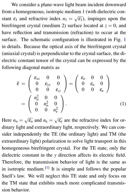
Fig. 1. Schematic diagram for electromagnetic solution of extraordinarylight plane-wave transmission/reflection at a birefringent crystal surface. (a)Electromagnetic field analysis for incident wave,reflection wave,and transmission wave. The electric field and magnetic field vector as well as the wave vector are explicitly marked. The crystal has its extraordinary axis(denoted by red arrow) parallel to the surface normal. (b) Analysis of the incident,reflection,and transmission beam direction,which is described by the incident angle α, reflection angle α, and refraction angle for transmission light wavefront φ and energy flux β.
2.1. Wave vector for transmission light


2.2. Reflection and transmission coefficient of field
The second critical step is to substitute Eqs. (4)–(6) into Eq. (3), find the explicit expression for (Eix,Erx,Etx), and utilize boundary conditions matching where the tangential components of the electric and magnetic field are continuous at the interface, namely,Eix|z=0+Erx|z=0=Etx|z=0andHiy|z=0+Hry|z=0=Hty|z=0. After some straightforward algebraic derivations, we can find the reflection and transmission coefficients of amplitude as
2.3. Electric field and displacement field for transmission wave
The third crucial step is to derive the explicit expressions for the electric fieldEtand electric displacement fieldDtwithin the birefringent crystal. This is not only important for obtaining a complete knowledge about light transport behavior, but also very important for better understanding of light–matter interaction such as nonlinear optical interaction of laser beam,[5,6]since only electric field is involved and relevant in these interactions.
The electric displacement fieldDtand then the electric fieldEtcan be directly derived from the magnetic fieldHt.They are given explicitly as
It is clear thatDtandEtare not parallel to each other, as should be the case for birefringent crystal.
2.4. Energy flux and reflection/transmission coefficient of intensity


So far we have obtained the explicit expressions for the incidence, reflection, and transmission light wave vector (ki,kr,kt) and energy flux (Si,Sr,St), then we can draw in Fig. 1(b) the overall physical picture on the reflection/transmission behavior of light after incident on the birefringent crystal.
We go further to derive the explicit expression for the reflection and transmission coefficients of light intensity in terms of energy flux,which are

2.5. Refraction angle for wavefront and energy flux
The fifth crucial step is to determine the angle of refraction for the transmission light, which is the central issue of the optics of birefringent crystals. For this purpose, we notice that the electromagnetic wave transport can be characterized by two quantities,one is the wave vectork,denoting the wavefront motion and phase evolution,and the other is the energy fluxS,denoting the electromagnetic energy flux motion.We will analyze in great details these two quantities in current problem. Obviously both cases of the incident and reflection light have identical wavefront angle and energy flux angle asα,because they are transporting and evolving in isotropic dielectric medium (such as air). In contrast, the transmission light has very different wavefront refraction angleφand energy flux refraction angleβin the case of extraordinary light incidence. Of course, for ordinary light incidence upon the birefringent crystal surface,we still haveφ=β. The two different polarization lights exhibit very different refraction angles, leading to the well-known birefringence production in uniaxial crystal.
The wavefront angleφfor the refraction light beam is determined by the wave vectorktand given explicitly as
The refraction angle of energy fluxβdetermines the true transport direction of transmission light beam with respect to the surface normal(as seen in Fig.1),and it is the right quantity of refraction angle that is generally referred to in practice of optics. This angle is related with the energy flux vectorStand given by

2.6. Reduction to isotropic medium
In the case that medium 2 is a homogeneous isotropic medium with dielectric constantε2and refractive indexn2,namely,εe=εo=ε2andne=no=n2, we find that equations (13) and (14) are identical, and now become tanφ=tanβ=n1sinα/[n22-n21sin2α]1/2,or equivalently

Equations (16) and (17) are just the well-known Fresnel formulas for field and intensity describing the reflection and transmission of light at the interface between two homogeneous and isotropic dielectric media,medium 1 and medium 2.
2.7. Index ellipse
Obviously the refractive index of the birefringent crystal for extraordinary light is not a constant, but shows strong spatial dispersion,namely,strongly varying with the transport direction,or refraction angle. It is a critical issue in the optics of crystals to extract the explicit form of such a spatial direction dependence. We consider both situations of wavefront refraction and energy flux refraction.
The refractive index governing the wavefront refraction behaviornphase(φ)is closely related with the wave vectorktof transmission light. It is well known that the wave number of light within a dielectric medium of indexnis given byk=k0n,and it is this quantity that determines the phase of light wave and its temporal–spatial evolution. To determine the value ofnphase(φ), we use the definition of wave number in combination with Eq.(7). Letx=nphasesinφandz=nphasecosφ,we find

Equation(18)is recognized as the index ellipse of birefringent crystal for the wavefront motion of light. In classical textbook of optics, such as Principle of Optics by Born and Wolf, this index ellipse is derived by quite a cumbersome procedure.[1]But now we use a very simple formulation originated from electromagnetic field solution to yield this classical result of index ellipse. Equation (18) immediately yields the explicit expression of the effective phase refractive index as

which means that the effective phase refractive index of birefringent crystalnphase(φ)[ornphase(α)]satisfies usual Snell’s law. This seems to indicate that now the birefringent crystal can be looked upon as an isotropic medium, but with its refractive index varying with the transport direction of light.
Now we consider the refractive index governing the energy flux refraction behaviornray,which is closely related with the energy fluxStof transmission light. It is well known that the energy flux of light within a dielectric medium of indexnis related with the energy density of lightwand the ray propagation speed of light beamv=c/n, and is given byS=w×v=wc/n. For the current birefringent crystal, the transmission light has an energy flux quantity as

This function is of course not an elliptical function with respect to the angleφ. The formulation ofnraywith respect to the ray refraction angleβis an even more complicated function, and thus we will not present it explicitly here. In another way,we can explicitly express this energy flux index as a function of the incident angleαfor convenience of comparison with experimental observation by considering Eq.(14b),which is

which means that the effective energy flux refractive index of birefringent crystal does not satisfy the usual Snell’s law.Thus unfortunately, the crystal cannot be looked upon as an isotropic medium when concerning the energy flux transport.On the other hand, for medium 2 being an isotropic medium with refractive indexn2,equations(19),(20),and(23)all yield the classical result asnphase(φ)=nray(φ)=n2.
2.8. Total internal reflection angle and zero-reflection Brewster angle
We go further to discuss several typical phenomena and laws that are well known in the history of optics and have become popular topics in basic optics even for high school students. Of course,frankly speaking,these phenomena and laws are referred to only for simple isotropic medium. Now we extend the concepts to the complicated birefringent crystals.
The first is the total internal reflection,which is a basic but very useful optical phenomenon. Total internal reflection happens when the transmission light is an evanescent wave which has vanishing vertical wave vector component,i.e.,ktz=0.Of course,this is only possible when light is passing from an optically thicker medium to an optically thinner medium,namely,for the casen1>n2. Then from Eq.(7)we immediately findn1sinα ≥nein order for total internal reflection to happen.Consequently, the critical incident angle for total internal reflection is explicitly given by

Another popular phenomenon in optics is the zero reflection of incident light against the surface of medium 2, which was first discovered about 200 years ago by Sir David Brewster and now has found broad applications in laser science and optical engineering. The corresponding angle is called Brewster angle. For current birefringent crystal,we will start from Eq.(9)and find the reflection coefficientr=0 at the condition ofnenocosα-n1[n2e-n21sin2α]1/2=0. This readily yields the formula as cosα=[(ε1εe-ε21)/(εoεe-ε21)]1/2,so that the Brewster angle is given by the following explicit expression:
Equations(25)and(26)can easily return back to classical result for isotropic medium. Forn1=n,ne=no=n2=1, we find from Eq. (25) the well-known formulation of critical total reflection angle asαcritical=arcsin(1/n);while forn1=1,ne=no=n2=n, we find from Eq.(26)the well-known formulation of Brewster angle asαB=arccos[1/(n2+1)1/2]=arctan(n).
3. Theoretical calculation for real examples of birefringent crystal
In the above discussion we have obtained explicit formulations for a series of physical quantities concerning the reflection and transmission of TM light at the surface of birefringent crystal,and the transport of light within the birefringent crystal via rigorous electromagnetic solution and consequent systematical analysis upon the electromagnetic field evolution and electromagnetic wave propagation. These analytical formulations should cover all important physics and optics for birefringent crystals. To demonstrate the power of the analytical theory, we proceed to consider LN crystal and Te crystal as two typical examples and perform theoretical calculations.The LN crystal is a negative uniaxial crystal withno=2.32,ne=2.23,at the concerned wavelength 532 nm, while the Te crystal is a positive uniaxial crystal withno= 4.80,ne= 6.20 at the wavelength 3 μm. It can be seen that LN is a weak anisotropic medium,while Te is a very strong anisotropic medium.We intentionally choose LN and Te crystals for better illustrating the contrast of birefringence effect in different birefringent crystals.
3.1. Refraction angle and refractive index
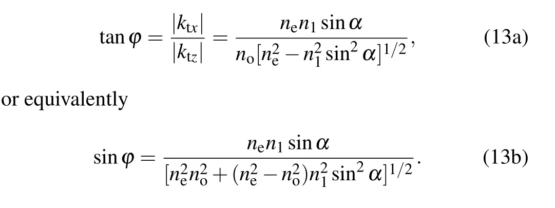
We first discuss the relationship of the refraction angle with the incident angle. Both the wavefront and energy flux refraction are considered simultaneously and comparison is made. Following Eqs. (13) and (14), we calculate and draw a graph about wavefront refraction angleφand energy flux refraction angleβwith the change ofα. The results are displayed in Figs. 2(a) and 2(b) for LN and Te crystals, respectively. When the incident angle increases from the minimum value 0°to the maximum value 90°,φandβalso increase,but with a difference in rising slope. It is obvious that there is a deviation angle betweenkandS. This deviation is small for the weak anisotropic crystal LN (with a maximal deviation of~2°and relative deviation~10%) and is big for the strong anisotropic crystal Te (with a maximal deviation of~5°and relative deviation~40%). As many popular birefringent crystals, such as those used in wave-plate (calcite,no=1.65,ne=1.48; quartz,no=1.544,ne=1.552)and those used in nonlinear optical frequency conversion(LN,no=2.32,ne=2.23; BBO,no=1.55,ne=1.67) only have weak anisotropy,the difference between the wavefront and energy flux refraction angle is not large.
Fig.2. The refraction angles φ and β as functions of the incident angle α for(a)LN crystal and(b)Te crystal,and the corresponding effective phase and ray refractive index nphase and nray as functions of the incident angle for(c)LN crystal and(d)Te crystal.
We go on to calculate the effective refractive index for the two refraction index, namelynphaseandnray, and make a comparison,following Eqs.(20)and(23). The results are displayed in Figs. 2(c) and 2(d) for LN and Te crystals, respectively. It can be seen that the difference innphaseandnrayis small in the entire range of incident angleα=0°–90°.The relative deviation quantity is below 0.5%,no matter for the weak anisotropic medium LN or for the strong anisotropic medium Te,which is far smaller than the deviation in refraction anglesφandβ. On the other hand,we combine Eqs.(13a)and(14a)and find

We can thus see clearly that for negative LN crystal,no>ne, soβ >φ, the energy flux refraction angle will be greater than the wavefront refraction angle,while for positive Te crystal,no<ne,soβ <φ,the energy flux refraction angle will be smaller than the wavefront refraction angle. All these features are exactly the case as shown in Fig.2. Besides, the greater difference betweennoandne,the greater deviation the two refraction angles will be.
3.2. Index ellipse
In the above analyses, we have considered the refraction of light incident from air to birefringent crystal and plot their variation as a function of the incident angle. Because LN and Te crystals have large average refractive index, so the refraction angle range is far smaller than the incident angle rangeα=0°–90°. For LN the maximal refraction angle is within 30°,while for Te crystal,the maximal refraction angle is below 15%. It is thus seen that the incident light in this configuration can only probe a small part of entire spatial dispersion diagram,namely the change of effective refractive indexesnphaseandnraywith respect to the transport direction of these two crystals,which should cover the angular range from 0°–90°.
For this purpose, we consider the change ofnphaseandnraywith respect to the refraction angleφin the entire angular range of 0°–90°,namely,the functionsnphase(φ)andnray(φ),and perform theoretical calculations following Eqs. (19) and(22). The results are displayed in Figs. 3(a) and 3(b) for LN and Te crystals,respectively. It has been argued from Subsection 2.7 thatnphase(φ)follows the rule of perfect index ellipse as described by Eq.(18),and satisfies the classical Snell’s law as described by Eq.(21),whilenray(φ)does not satisfy these two rules. Yet,as shown in Fig.3(a),for the weak anisotropic medium LN,nphase(φ) is very close tonray(φ) in the entire angular range, so thatnray(φ) also follows the rule of index ellipse and Snell’s law. These two indices both reduce fromno=2.32 atφ=0otone=2.23 atφ=90o. In contrast,for the strong anisotropic medium Te,nphase(φ) is close tonray(φ)only in the small angle range 0o≤φ ≤15oand large angle range of 80o≤φ ≤90o,but has considerable deviation in the middle angle range of 15o≤φ ≤80o. Despite the deviation,the two indices still increase fromno=4.8 atφ=0otone=6.2 atφ=90o,although following a different slope of growth.
Summarizing all the above discussions and following Eq. (18), we plot in Figs. 3(c) and 3(d) the index ellipse to describe both qualitatively and quantitatively the effective refractive index,together with the explicit illustration of the direction of wave vectorkand energy fluxS, for both LN and Te crystals,respectively.The diagrams are well known in classical optics textbook. It can be seen that for light transporting parallel with the uniaxial direction (zaxis), the effective refractive index isno, because this is the purely ordinary light whose electric field is parallel to the ordinary axis. In contrast,for light transporting perpendicular to the uniaxial direction(xaxis), the effective refractive index isne, because now this is the purely extraordinary light whose electric field is parallel to the uniaxial axis. In other directions described byk, the effective refractive index takes other values betweennoandne.All these features are in accordance with the theoretical calculation results illustrated in Figs. 3(a) and 3(b). The major advantage for this index ellipse diagram is that one can directly obtain the precise value of effective refractive index for a given transport direction by looking into this diagram. But our current theory indicates that this procedure only holds for wavefront refractive indexnphase(φ) but not for energy flux refractive indexnray(φ).

Fig.3. Effective refractive index change in the entire angular range. Panels(a) and (b) illustrate the change of nphase(φ) and nray(φ) for LN and Te,while panels(c)and(d)show the schematic plot of index ellipse for LN and Te, together with the explicit illustration of the direction of wave vector k and energy flux S.
3.3. Reflection and transmission coefficients
In addition to the knowledges of refraction angle and refractive index against a given incident light at a particular incident angle, it is highly desirable to obtain the knowledges about the reflection and transmission coefficients and the electromagnetic field evolution behavior above and within the birefringent crystal. Following Eqs. (9) and (12), we calculate the reflection and transmission coefficients for different incident angleα=0°–90°. The results are displayed in Fig.4 for LN and Te crystals.

Fig. 4. Calculated reflection (R) and transmission (T) coefficients of light intensity for light incident from air upon the surface of (a) LN and (b) Te birefringent crystals under different incident angles.
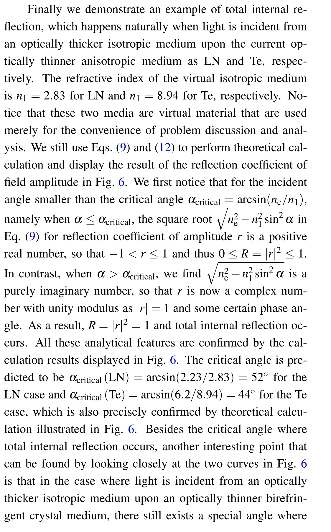
It is interesting to find that the reflection coefficient first reduces with increasing incident angle, and reaches exactly 0% at some certain angle, and then quickly rises to exactly 100%atα=90o. This feature well accords with the isotropic medium case that has been discussed extensively in standard textbooks of optics and electrodynamics. A close look shows that the angle with zero reflection coefficient is 67°and 78°for LN and Te crystals,respectively. This angle is well known as the Brewster angle, which can be calculated following Eq.(26).The result isαB(LN)=67°andαB(Te)=78°,identical to the value extracted from the data plotted in Fig.4.

Fig.5. Magnetic field Hy pattern illustrating reflection and transmission of light incident from air upon the surface of birefringent crystal LN and Te under different incident angles. (a) LN, α =80° with large reflection; (c)LN,α =67° with zero reflection at Brewster angle; (e)LN,α =30° with weak reflection;(b)Te,α =85° with large reflection;(d)Te,α =78° with zero reflection at Brewster angle;(f)Te,α=70°with weak reflection. Both traveling wave and interference wave patterns are clearly illustrated. In each figure the directions of crystal surface normal, incident angle, wave vector k,and energy flux S are marked explicitly.
The quantity of reflection coefficient can also be visualized from the electromagnetic wave evolution and field distribution characteristics. When significant reflection occurs,the reflected light will interfere with the incident light,leading to significant interference pattern of electromagnetic field. In contrast, when zero reflection takes place at the Brewster angle,no interference pattern exists and only pure traveling-wave field pattern exists at the incidence region. In the case of weak reflection,the interference pattern is not apparent but still visible. These features predicted by analytical theory are well disclosed by the theoretical calculation results as displayed in Fig.5 for both LN and Te crystals at several typical situations of incident angles corresponding to large reflection, zero reflection, and weak reflection. From the field patterns we can directly distinguish the direction ofkandSwith respect to the crystal surface normal.

Fig.6. Calculated reflection coefficient r as a function of the incident angle.The light is incident from an optically thicker isotropic medium upon the optically thinner birefringent crystals LN and Te,respectively. (a)Isotropic medium with n1=2.83 together with LN crystal;(b)isotropic medium with n1=8.94 together with Te crystal.

4. Experimental confirmation of Brewster angle
The optics of birefringent crystals has a long history.Many things, phenomena, and laws discussed in this paper have been well known,but addressed in a rather cumbersome way.We take a relatively less studied issue,the zero-reflection Brewster angle, for deeper study and perform experiment to confirm theoretical prediction. The phenomenon of zero reflection at Brewster angle has been popularly used in laser technology and nonlinear optics devices,where in many situations the ordinary technique of anti-reflection coating on the surfaces of laser crystal and nonlinear crystal might not be convenient. In our experiment, we use az-cut LN thin film with thickness of 1 mm and green laser light at wavelength 532 nm. The LN crystal has its uniaxial orientation parallel to the crystal surface normal, and the laser beam of diameter larger than 1 mm and at TM polarization is incident upon the LN crystal to perform reflection experiment.The LN crystal in placed in ordinary clean-room environment so that the background medium is air withn1=1.The experimental setup perfectly matches with the theoretical assumption adopted in this work.The incident angle is adjusted from 0°to 90°by rotating the LN crystal. The experimental data are displayed in Fig.7 by the dotted curve. Nearly zero reflection indeed occurs at the expected Brewster angle of 67°,indicating good agreement between theory and experiment. In the practice of laser technology and nonlinear optics research, people usually adopt a simplified model by looking upon the birefringent crystal as an isotropic medium with average refractive index and then using classical formula of Brewster angle for isotropic medium to find out the right value of zero-reflection angle. Obviously,our current theory and formulation can make a more accurate prediction about this important optics quantity in very general situations.
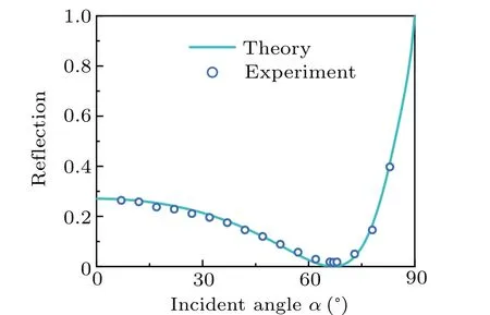
Fig. 7. Plot of reflection coefficient for 532-nm laser light incident upon an LN birefringent crystal plate obtained by both theoretical calculation and experimental measurement. The two curves cover the incident angle ranging from 0° to 90° and both exhibit zero reflection right at the predicted Brewster angle of 67°.
In other incident angles, the reflection coefficient is not zero. In addition to the direct reflection of light from the front surface, we have also considered in our theoretical calculation the secondary reflection from the back surface of the LN crystal to account for the total reflection signal observed in experiment. The calculation is still based on the formulations in Eqs. (9) and (12), but uses the combination of reflection and transmission coefficients. The theoretical calculation result is plotted also in Fig.7 for comparison. Good agreement between theory and experiment is obvious. This simple experiment makes a good confirmation of the predicted value of Brewster angle for the LN birefringent crystal and thus provides a strong support for the correctness, accuracy, and efficiency of the developed electromagnetic theory for the classical problem of crystal optics.
5. Conclusion
In summary,we have studied the classical problem in optics and physics about the propagation of light within natural birefringent crystal with principal refractive index of (ne,no)from the point of view of electromagnetic field evolution and wave motion. These problems have been extensively studied for more than one century and the solutions have been presented and discussed in many standard textbooks,such as classical Principle of Optics by Born and Wolf. However, these solutions and discussions look quite complicated and cumbersome, are hard to understand, and the formulations are difficult to use. Therefore, such complicated presentations have hindered interest of deep study by university students, general readers, and even optics professionals about the important topics as the optics of crystals, which have found broad applications in many modern linear optical materials and devices,as well as laser technology and nonlinear optics devices.Besides,the reflection/transmission coefficient at the birefringence crystal surface is less known compared with the refraction angle. To make things easier, in this work we have developed a simple, comprehensive while rigorous electromagnetic solution to these problems and build up a complete picture about the physics underlying the crystal optics.
We have focused on a typical situation where the uniaxial crystal axis is perpendicular to the crystal surface and the incident light from an isotropic medium upon the birefringent crystal surface is in the TM polarization state (i.e.,the extraordinary light) with non-vanishing field components(Hy,Ex,Ez). We have intentionally neglected the TE polarization (i.e.the ordinary light) because in this case the birefringent crystal is identical to a trivial isotropic medium. By assuming that the incident light,reflection light,and transmission (refraction) light are all plane waves, and then solving Maxwell’s equations for the electromagnetic fields in combination with electromagnetic boundary conditions and translational symmetry, we have easily obtained the explicit formulations for all relevant physical and optical quantities.
We first derive the dispersion relationship between the parallel and perpendicular components of wave vectorktxandktzin reference to the incident angleαand angle frequencyωwithin the anisotropic birefringent crystal. Then we derive the reflection and transmission coefficientsrandtof magnetic field by using the electromagnetic boundary conditions, from which the magnetic fieldsHi,Hr,Ht, and then the electric fieldsEi,Er,Et,and the displacement fieldsDi,Dr,Dtcan be derived straightforward. This would set the basis for acquiring all the characteristics of electromagnetic field evolution and wave motion within the birefringent crystal, as well as in the incident isotropic medium. These include the important physical quantity of energy flux vectorsSi,Sr,St, from which the reflection and transmission coefficients of light intensitiesRandTcan be obtained as a function of the incident angle.
Both the wave vectorkand energy flux vectorScan characterize the electromagnetic wave transport behavior, withkdenoting the wavefront motion and phase evolution, andSrepresenting the electromagnetic energy flux motion. We have acquired the wavefront refraction angleφand energy flux refraction angleβfrom the directions ofkandS, respectively for the transmission (refraction) light as a function of the incident angleα. We have gone further to derive the refractive index governing the wavefront refraction behaviornphasedirectly from the magnitude and direction of wave vectorktand the refractive index governing the energy flux refraction behaviornraydirectly from the magnitude and direction of the energy fluxSt. Interestingly, we have found thatnphasesatisfies the classical Snell’s law asnphase(φ)sinφ=n1sinαand thus can be calculated directly from the refraction angleφ,while in contrast,nraydoes not satisfy the classical Snell’s law asnray(β)sinβ/=n1sinαand thus cannot be calculated directly from the refraction angleβ. Moreover, we have found thatnphase(φ) satisfies the classical formulation of index ellipse with the principal axis ofneandno,and thus it can also be calculated directly by reading the diagram of index ellipse for a given refraction angle (also the wavefront motion) angleφ. These operations have clearly shown that analysis over the electromagnetic field evolution and electromagnetic wave motion can greatly help one to derive many critical physical and optical quantities concerning the extraordinary refraction behavior of light within the birefringent crystal in a simple and straightforward way. Frankly speaking, such a solution is much more simple and comprehensive in comparison with the cumbersome derivation and solution presented in standard textbooks concerning the optics of birefringent crystals.
Besides the above physical and optical quantities that have been well concerned and discussed in textbooks of optics,we have also paid attention to several less concerned and discussed quantities about the optics of birefringent crystals,including the zero-reflection Brewster angle and the critical angle for total internal reflection. We have derived and acquired explicit formulations for these two important quantities. They are also simple and comprehensive, and thus will be beneficial for easy understanding of these special optical phenomena for general students and layman readers.
We have found that when the birefringent crystal becomes an ordinary isotropic medium withne=no=n2,all the above formulations are reduced to the well-known results for light reflection and transmission(refraction)at the interface between two isotropic media. Although this of course should be the case, the fact that our electromagnetic approach developed for birefringent crystals is nearly as simple and comprehensive as the classical approach (e.g.Fresnel’s formulae) suitable for much simpler problems of isotropic media is once again a strong evidence that this new approach is simple,comprehensive, efficient, but still rigorous and accurate. To further confirm its effectiveness and efficiency,we have taken the weak birefringent crystal LN and the strong birefringent crystal Te as two comparison examples and performed extensive and systematic theoretical calculations and analyses on all the important quantities of these two birefringent crystals. The results should help to deepen our understanding. Moreover,we have performed experimental measurement to confirm Brewster angle and found excellent agreement between theory and experiment.We believe these simple explicit analytical formulations developed in this work can greatly help general university students of optics and physics as well as layman readers to raise greater interest of study to the optics of crystals, and offer them a simple tool to construct a simple,comprehensive and complete picture about all relevant light transport characteristics in birefringent crystal,in both qualitative and quantitative manners.These explicit analytical formulations on electromagnetic field evolution and electromagnetic wave motion can also help one to deeply investigate nonlinear optical interaction and construct a rigorous solution to laser transport and frequency conversion dynamics in popular nonlinear crystals,many of which are birefringent crystals,such as LN and BBO.This will in turn help to build better laser technology and open up new applications.
Acknowledgements
Project supported by the National Key Research and Development Program of China(Grant No.2018YFA 0306200),the National Natural Science Foundation of China (Grant No.11974119),the Science and Technology Project of Guangdong Province, China(Grant No.2020B010190001), and the Guangdong Innovative and Entrepreneurial Research Team Program(Grant No.2016ZT06C594).
猜你喜欢
Chinese Physics B(2022年11期)2022-11-21
美食(2022年5期)2022-05-07
Chinese Physics B(2022年4期)2022-04-12
电影文学(2021年17期)2021-10-14
作文评点报·低幼版(2020年42期)2020-12-14
人才资源开发(2020年15期)2020-09-08
山西教育·招考(2019年6期)2019-09-10
对联(2018年11期)2018-02-22
神州·时代艺术(2017年6期)2018-01-13
小学生作文·小学低年级适用(2016年1期)2016-03-07
- Chinese Physics B的其它文章
- A nonlocal Boussinesq equation: Multiple-soliton solutions and symmetry analysis
- Correlation and trust mechanism-based rumor propagation model in complex social networks
- Gauss quadrature based finite temperature Lanczos method
- Experimental realization of quantum controlled teleportation of arbitrary two-qubit state via a five-qubit entangled state
- Self-error-rejecting multipartite entanglement purification for electron systems assisted by quantum-dot spins in optical microcavities
- Pseudospin symmetric solutions of the Dirac equation with the modified Rosen–Morse potential using Nikiforov–Uvarov method and supersymmetric quantum mechanics approach