
A multi-frequency circularly polarized metasurface antenna array based on quarter-mode substrate integrated waveguide for sub-6 applications
2022-05-16 07:09HaoBai白昊GuangMingWang王光明XiaoJunZou邹晓鋆PengXie谢鹏andYiPingShi石一平
Chinese Physics B 2022年5期
关键词:光明
Hao Bai(白昊), Guang-Ming Wang(王光明), Xiao-Jun Zou(邹晓鋆), Peng Xie(谢鹏), and Yi-Ping Shi(石一平)
Air and Missile Defend College,Air Force Engineering University of China,Xi’an 710051,China
Keywords: substrate integrated waveguide,circularly polarized,quarter-mode,antenna
1. Introduction
The 5G wireless network technology leads to the fourth industrial revolution. As the terminal of the wireless communication,the 5G antenna is a research hotspot.[1,2]At present,the commercial frequency band of 5G is focused on sub-6 frequency bands.[3,4]The most popular bands are the n41/n78 and n79 frequency bands. The research on antenna miniaturization is in the ascendant stage because of the limitation of the installation platform size. Secondly, considering the cost reduction and multi-function of antenna,multi-frequency band or time-sharing mode is necessary.[5–7]Thirdly,the circularly polarized antennas are preferable in wireless communication as compared with linearly polarized counterparts because of mitigating multipath fading.[8]Thus, the miniaturized multifrequency circularly polarized array has received more attention from researchers. In Ref. [9], a compact triple-band circularly polarized quadrifilar helix antenna through the combination of a UHF-band and an L/S-band is designed. A multiband circular polarization (CP) antenna operated in WLAN and WiMAX band is designed in Ref.[10].
The substrate integrated waveguide (SIW) antennas are widely used in the modern antenna design due to the advantage of high Q value and easy integration with the circuitry.[11–13]The researchers introduced the principle of magnetic wall and studied the half-mode and quarter-mode SIWs (QMSIW) to realize the compact size.[14,15]Recently, metasurface has received more and more attention. As a new developed technology, applications of metasurface are increasing, including broadening the bandwidth,[16]improving the gain,[17]beam control,[18,19]and rotation of polarization.[20]The metasurface plays an important role in improving the parameters of the antenna. A lot of researchers have obtained many positive achievements in the multi-frequency circularly polarized SIW antennas.[21,22]In Ref. [23], a novel SIW self-triplexing slot antenna is proposed for multiple frequency application. Three new designs of self-quadruplexing are presented with different senses of CP in Ref. [24]. Four unequallength T-slots on the top of an SIW cavity generate CP in four different bands.However,in the process of designing multi-frequency antenna array,the distance between units should satisfy certain requirements to avoid the grating lobe.[25]Virtually,the antenna size will increase, so reducing the antenna size as much as possible to achieve miniaturization is still a problem to be solved urgently in the antenna design.
A miniaturized multi-frequency circularly polarized array based on quarter-mode substrate integrated waveguide is proposed for sub-6 applications in this paper. The antenna array is composed of three independent sub-arrays to achieve three circularly polarized frequency bands (2.5/3.5/4.8 GHz). And each of the sub-arrays employs the modified QMSIW.By introducing a strip-slot,the impedance bandwidth of the antenna array is broadened while the dimension is decreased by 75%to realize the miniaturization. Four elements are assigned in the rotation order[26]to achieve the circular polarization. Meanwhile, the metasurface leads the impedance bandwidth of the sub-array to be further enhanced.Taking the antenna operating at 2.5 GHz for example,the sub-array achieves an impedance bandwidth of 11.6% and an axial ratio bandwidth of 8.8%.And the gain is 6.2 dBi in the operating frequency band.Moreover, the metal vias are employed in the antenna array design to further achieve miniaturization.[27]The antenna array is manufactured and measured. Both the simulated and measured results show that the antenna array achieve impedance bandwidths of 10%, 11.7%, and 14.8% and axial ratio bandwidths of 8.8%, 8.0%, and 8.5% at 2.5 GHz, 3.5 GHz, and 4.8 GHz, respectively . Meanwhile, the gain is stable in the operating band within an uncertainty of 0.7 dBi.
2. Antenna sub-array design and analyze
2.1. Configuration of antenna aub-array 1
The top view and the side view of the antenna sub-array 1 are given in Fig. 1. The whole sub-array 1 consists of three substrate layers and four metal layers. The metasurface is etched on the upper face of the top substrate with a thickness of 1.5 mm. The slot plate and ground are etched on the double faces of middle substrate with a thickness of 1.5 mm. And the metal vias each with diameter ofDsiwand distance ofPsiware employed to connect the patches and ground. The feeding network is on the back side of the bottom substrate with a thickness of 0.6 mm. The end of the feeder is connected to patch by metal pin to feed. There is one air layer of 1.0 mm between the top substrate and middle substrate. All of the substrates are F4b with a dielectric constant of 2.65.

Fig.1. Top view and side view of antenna sub-array 1,with dimensions being Lp=6,Lm=11.6,Dm=1.2,H1=1.5,H2=1.5,H3=0.6,and Hair=1,all in units of mm.
2.2. Design of antenna element
Figure1 shows the main radiation body of the antenna sub-array 1 which includes the middle substrate and patch etched on its double faces. The four modified QMSIW units are assigned in the rotation order to constitute the corresponding input ports with phases of 0°, 90°, 180°, and 270°, respectively. The structure of the proposed element is given in Fig. 2 and the element is coaxial feed. The metal vias with diameter ofDsiwand distance ofPsiware employed to connect the patches and ground.In recent years,many researchers have conducted the theory and application analysis of QMSIW and obtained a lot of research achievements.[28]Although the typical QMSIW antennas reduce the antenna size,[29]the operating bandwidth is narrow. As shown in Fig. 2, to further improve the operating bandwidth and usability of antenna,the antenna element is modified by introducing the strip slot on the basis of a typical QMSIW antenna.The antenna element is compact in structure and easy in fabrication,which integrates the advantages of SIW and the operating bandwidth.
In the previous study,it has been found that for QMSIW,the upper right metal edge is the equivalent to magnetic wall while the lower left edge separated by the metal vias is electrical wall. The electrical wall can reduce the energy loss which can provide the basis on further studying the shared metal vias.As is well known, etching the slot on the radiation patch to attach parasitic mode is a kind of effective mean to broaden the operating bandwidth. In Fig. 2, the whole metal patch is taken as QMSIW and the patch is divided into two similar parts by the strip slot. The triangle at the upper right can be regarded as the eighth-mode SIW. Then the modified antenna attaches the eighth-mode on the basis of quarter-mode and both of the two modes operate together to broaden the operating bandwidth. Figure 3 shows the curves of simulatedS11versusfrequency of antenna with and without strip slot(QMSIW and the proposed element). It is clearly manifested that by introducing this strip slot, the element bandwidth is improved from 20 MHz (2.49 GHz–2.51 GHz) to 120 MHz(2.5 GHz–2.62 GHz).
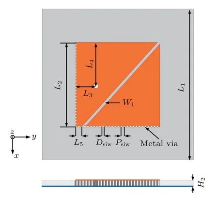
Fig. 2. Top view and side view of proposed antenna element, with dimensions L1 =45, L2 =25, L3 =6, L4 =13, L5 =1.8,W1 =0.8, Dsiw =0.5,and Psiw=0.9,all in units of mm.
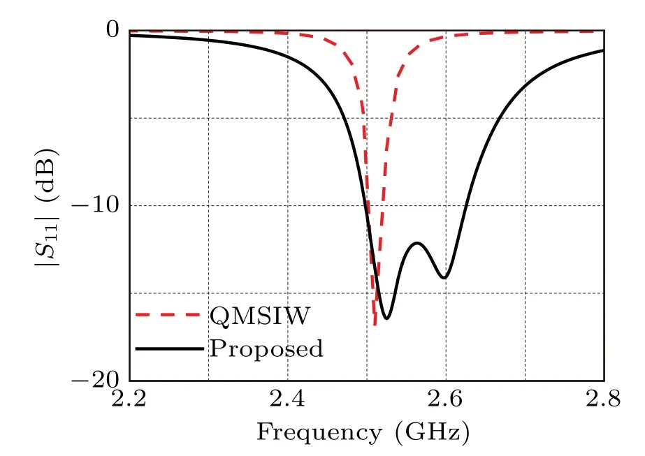
Fig.3. Curves of simulated S11 of antennas with and without strip slot for QMSIW and proposed antenna.

Fig.4. Simulated surface current distribution of antenna element.
The simulated surface current distribution of proposed antenna element at resonance points including 2.52 GHz and 2.6 GHz are given in Fig. 4 to analyze the operating principle.We can see that the surface current distribution focuses on the lower right part at 2.52 GHz while on the whole patch at 2.6 GHz. This shows that the lower frequency band of the antenna element is due to the eighth-mode while the QM mainly affects the higher frequency band.

Fig. 5. Curves of simulated S11 versus frequency (a) for different vales of W1,and(b)for different vales of L5.
In order to find the optimal solution and simplify the design of antenna,parameter learning is conducted. We change only one parameter each time, with other parameters remaining unchanged, so as to determine the optimal solution and obtain good impedance matching. To verify the correctness of analysis and analyze the influence of the strip slot on the antenna,we simulatedS11by using different vales ofL5andW1,and show the results in Fig. 5. As demonstrated in Fig. 5(a),asW1increases,the lower resonant frequency moves towards higher frequencies while the higher part remains unchanged.This indicates that the width of the strip slot affects only the attached mode(eighth-mode), but not the radiation mode obtained by the antenna itself. Therefore, choosing appropriate value ofW1can appropriately adjust the operating bandwidth.Figure 5(b) displays the curves of simulatedS11versusfrequency with different values of slot edge distanceL5. Both the lower and the higher resonant frequencies move to the center and the impedance matches becomes better,which implies that the slot changes the original current distribution.AsL5increases,the lower right triangle part becomes smaller and the resonant frequency rises. So the lower frequency band moves towards higher frequency,which verifies the deduction that the lower resonant frequency is obtained by the attached mode.Meanwhile,the varyingL5results in the transformation of the left triangle. Also, when the current distribution is changed,the resonant frequency at higher band is affected. UltimatelyL5=1.8 mm is selected following the changing rule ofL5.
2.3. Feeding network
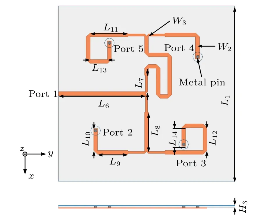
Fig. 6. Structure of feed network, with dimensions L6 =37.5, L7 =7.2,L8=17,L9=13.2,L10=11.1,L11=16.3,L12=9.8,L13=7.5,L14=8.1,W2=1.66,and W3=0.9,all in units of mm.
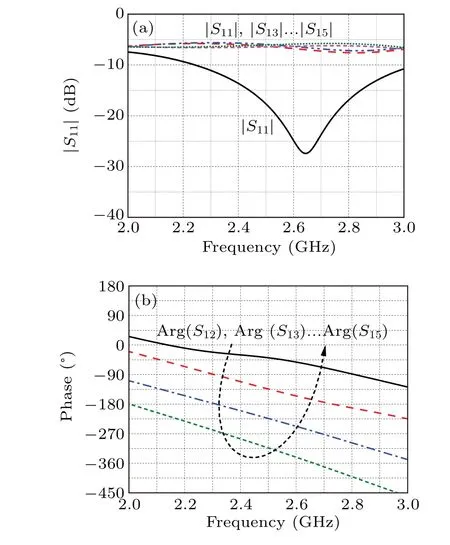
Fig. 7. Curves of simulated (a) S11 versus frequency and (b) phase versus frequency of feed network.
The feeding network of sub-array 1 is shown in Fig.6 and is composed of a 50-Ω microstrip line and a 70.7-Ω microstrip line situated on the bottom of the substrate while the other side is ground. Among the input phase of port 2,port 3,port 4,and port 5,the phase difference between the two adjacent ports is 90°thereby constituting a feed form required by the circularly polarized array. The phase difference is adjusted by the length of 50-Ω microstrip line. It is worth mentioning that the port 4 and port 5 have a 180°difference in comparison with the port 2 and port 3. This difference in phase is adjusted by the length of the C-shaped microstrip line. All metal pins of the ports are connected with patch elements to guarantee the feeding of the sub-array 1. Figure 7 shows the curves of simulatedSparameter and phaseversusfrequency for feed network. As can be seen from Fig. 7(a), theS11<-10 dB in a frequency range from 2.2 GHz to 3.0 GHz and the magnitudes ofS12–S15are almost the same. From Fig. 7(b), we can see that the phase difference between the two adjacent ports in the four ports is about 90°near the frequency point 2.5 GHz. So the proposed feeding network satisfies the requirement for sub-array.
2.4. Performance analysis of antenna sub-array 1
In the previous research, metasurface is used to further broaden the operating bandwidth. By adding the new radiation mode on the basis of original main radiation body,the new resonant point is introduced and thus the bandwidth is broadened. In the proposed sub-array 1, metasurface is introduced as shown in Fig.1. The metasurface is on the upper face of the top substrate. Four QMSIW elements constitute a radiation array and the operating bandwidth can be further improved.To prove the validity of the design, the sub-array 1 is fabricated and measured. The array is measured by an AV 3672B vector network analyzer and the standard anechoic chamber.The simulated and measured results of sub-array 1 antenna with and without metasurface are given in Fig.8. As shown in Fig.8(a),the operating bandwidth is improved from 140 MHz(2.53 GHz–2.67 GHz) to 290 MHz (2.42 GHz–2.71 GHz)by introducing metasurface. And the metasurface mainly affects the lower frequency band. The measured bandwidth is 260 MHz(2.44 GHz–2.70 GHz)and is close to the simulated result. Little difference is due to the machining error. Figure 8(b) shows the gain of the sub-array 1 antennas with and without metasurface. The gain of the proposed sub-array 1 is stable in the whole working frequency band. Compared with the gain in the case without metasurface antenna, the gain at lower frequency band is improved. The new resonance mode is obtained and the lower frequency range is broadened. The upper frequency range remains unchanged which shows the metasurface mainly improves the operating bandwidth and the gain improvement is limited.
The sub-array 1 is of left hand circular polarity(LHCP).The simulated and measured axial ratio and gain at 2.5 GHz are given in Fig. 9 respectively. As shown in Fig. 9(a), the axial ratio is less than 3dB at a frequency band of 2.43 GHz–2.65 GHz,which conforms to the circular polarization condition. Figure 9(b)shows the gain of the sub-array 1 at 2.5 GHz,we can see that the measured results accord well with the simulated results. The cross-polarization characteristic is good,and the antenna shows good circular polarization characteristics.
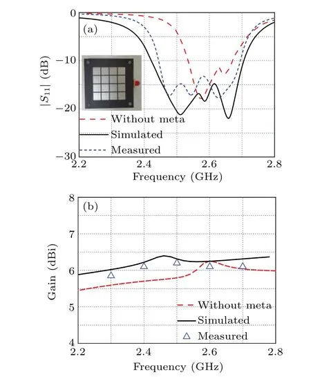
Fig.8. Curves of simulated and measured(a)S11 versus frequency and(b)gain versus frequency of sub-array 1 antennas with and without metasurface.
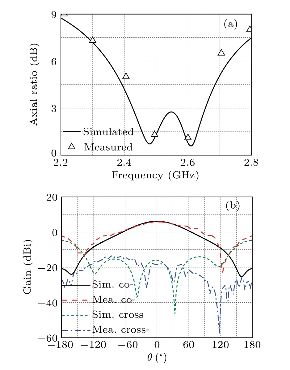
Fig. 9. Curves of simulated (Sim.) and measured (Mea.) (a) axial ratio versus frequency and(b)gain versus theta of sub-array 1 antenna.
Discussed above is the sub-array 1 which operates at the n41frequency band (2515 MHz–2675 MHz) of sub-6. The proposed tri-frequency antenna is composed of sub-array 1 operating at n41 (2515 MHz–2675 MHz)band, sub-array 2 operating at n78 band (3400 MHz–3500 MHz/3500 MHz–3600 MHz), and sub-array 3 operating at n79 band (4800 MHz–4900 MHz). In the same way,we can obtain the sub-array 2 and sub-array 3 by adjusting the corresponding parameters. The simulated and measured results of sub-array 2 antennas with and without metasurface are given in Fig. 10. According to Fig. 10(a), the operating bandwidth is improved from 310 MHz(3.51 GHz–3.82 GHz)to 440 MHz (3.38 GHz–3.82 GHz) by employing the metasurface. The measured results are in good agreement with the simulation results. Figure 10(b) shows the gain of the subarray 2 antennas and we can see that the gain is stable in the whole operating bandwidth. Compared with the gain of antenna without metasurface, the gain at lower frequency band is improved which has the same varying tendency as sub-array 1. And this explains in more detail that the metasuface improves mainly the operating bandwidth and the gain improvement is limited. The sub-array 2 is of LHCP, the simulated and measured axial ratio and gain at 3.5 GHz are shown in Fig.11. The axial ratio is less than 3 dB in a frequency band of 3.4 GHz–3.64 GHz which conforms to the circular polarization condition as shown in Fig. 11(a). Figure 11(b) shows the gain of the sub-array 1 at 3.5 GHz,indicating that the measured results are in satisfactory agreement with the simulated results. The cross-polarization characteristic is good and the antenna possesses good circular polarization characteristics.to 4.94 GHz (560 MHz), which shows good agreement with the simulated results. Figure 12(b)gives the gains of the subarray 3 antennas with and without metasurface and we can see that the stability of the gain is good. Also the sub-array 3 is of LHCP, the axial ratio bandwidth ranges from 4.46 GHz to 4.8 GHz as shown in Fig. 13(a). The simulated gain and measured gain of the sub-array 3 are given in Fig. 13(b) and good agreement is obtained, showing good circular polarization characteristic. The parameters of the three antenna elements are shown in Table 1.
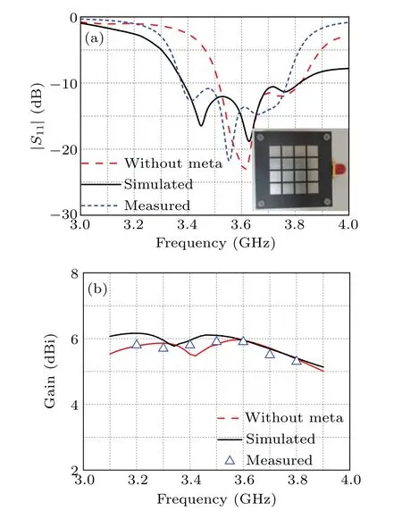
Fig. 10. Curves of simulated and measured (a) S11 versus frequency and(b)gain versus frequency of sub-array 2 antennas with and without metasurface.
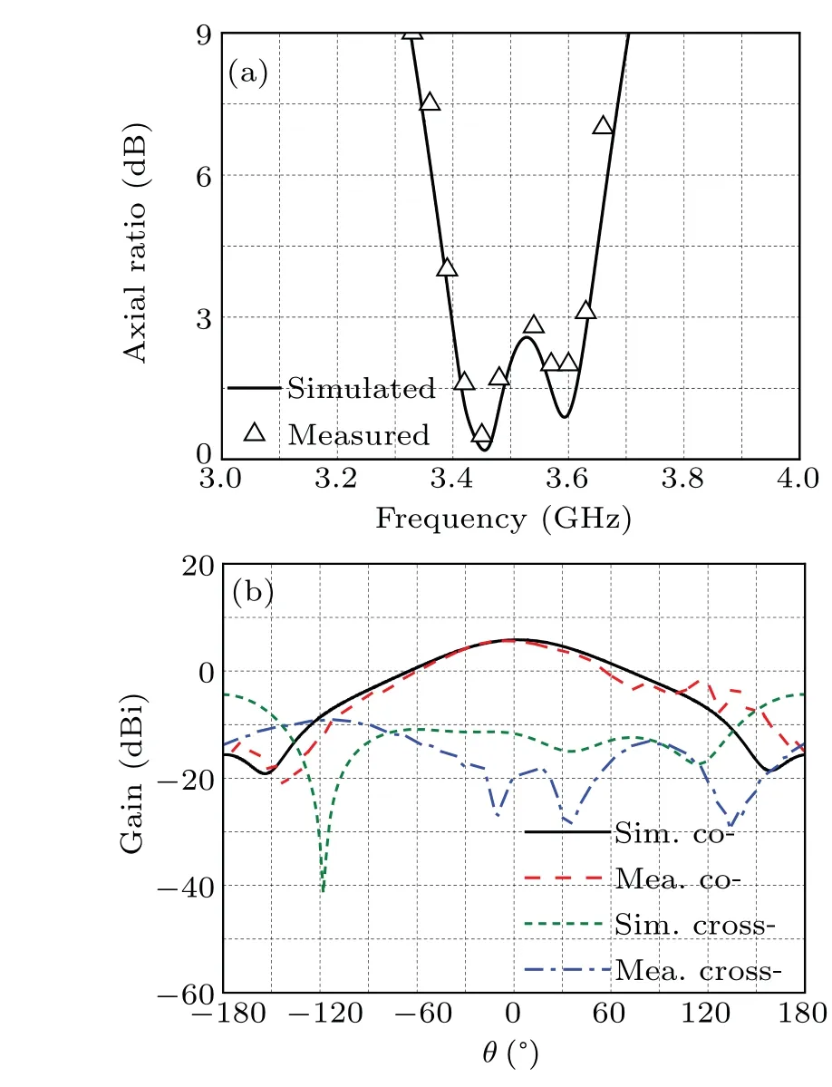
Fig. 11. Curves of simulated (Sim.) and measured (Mea.) (a) axial ratio versus frequency and(b)gain versus θ of sub-array 2 antenna.
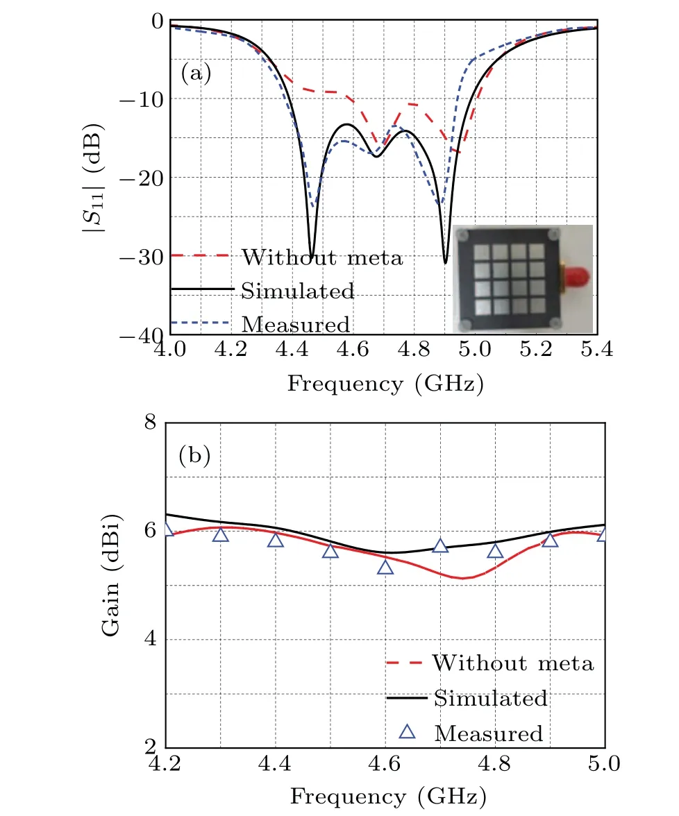
Fig.12. Curves of simulated and measured(a)S11 versus frequency and(b)gain versus frequency of sub-array 3 antennas with and without metasurface.
Similarly, the simulated and measured results of subarray 3 antennas with and without metasurface are shown in Fig. 12. It can be clearly seen from Fig. 12(a) that the bandwidth is broadened from 420 MHz (4.59 GHz–5.01 GHz) to 600 MHz (4.39 GHz–4.99 GHz) when the metasurface is introduced. The measured operating band is from 4.38 GHz
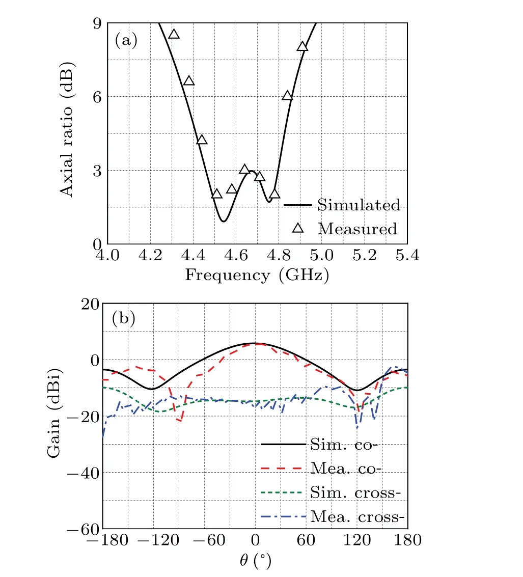
Fig. 13. Curves of simulated (Sim.) and measured (Mea.) (a) axial ratio versus frequency and(b)gain versus θ of sub-array 3 antenna.
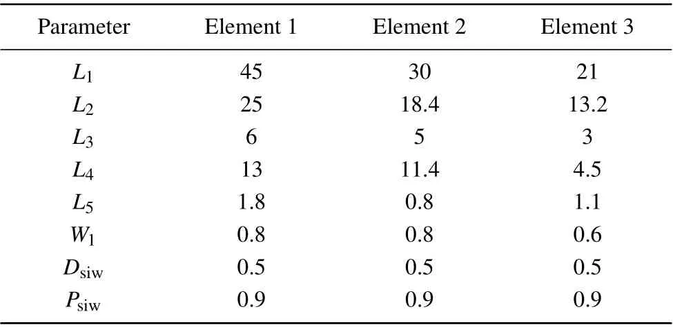
Table 1. Antenna parameters(in units of mm).
3. Antenna array design and discussion
In the above analysis,we mentioned that for QMSIW,the metal vias edge is the equivalent to electrical wall. And the coupling of the adjacent elements will be small. So considering the limitation of sub-6 antenna array size,the shared metal vias are introduced to further achieve miniaturization. The configuration of the antenna array is given in Fig. 14 and the array is composed of three substrate layers and four metal layers the same as the sub-array.The QMSIW sub-array is placed in triangle and the adjacent elements in the center shares the metal vias to reduce the antenna size. The antenna array is fabricated and measured to verify the design. The array is measured by an AV 3672B vector network analyzer and the standard anechoic chamber. Figure 15 shows a prototype of the antenna array and the measurement environment.
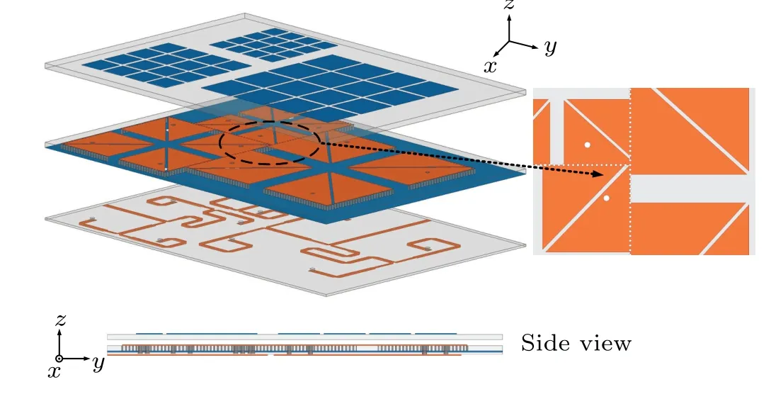
Fig.14. Configuration of antenna array.
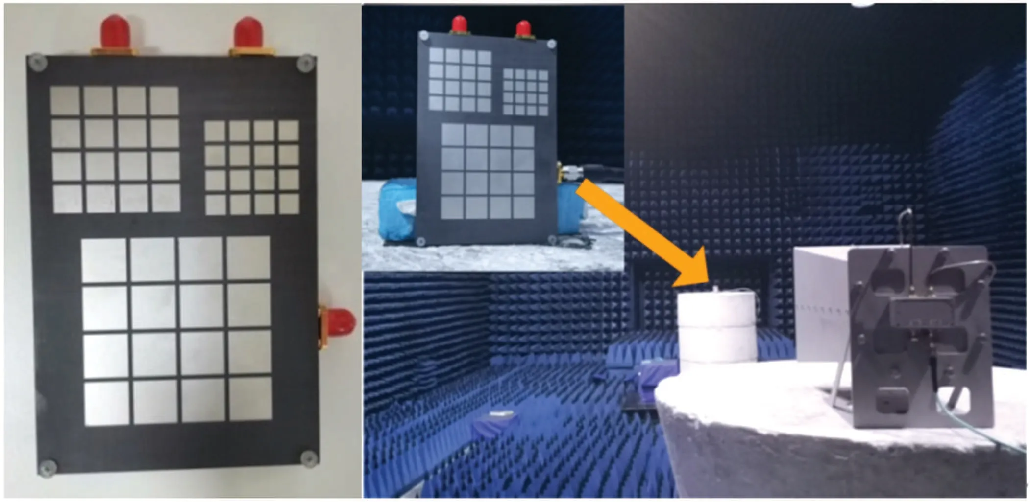
Fig.15. Configuration of antenna array.
The simulated and measuredS11of the antenna array are given in Fig. 16 and theS11of the antenna array does not change much compared with theS11of sub-array. The simulatedS12,S13, andS23are less than-20 dB in the whole frequency band, which shows the validity of shared metal vias. Although the three sub-arrays are close to each other,the coupling is small due to their strong independence. The simulated/measured operating frequency bands are 250 MHz(2.46 GHz–2.71 GHz)/230 MHz (2.49 GHz–2.72 GHz),410 MHz (3.39 GHz–3.80 GHz)/360 MHz (3.40 GHz–3.76 GHz), and 710 MHz (4.37 GHz–5.08 GHz)/700 MHz(4.32 GHz–4.92 GHz),respectively.
Figure 17 displays the frequency-dependent measured and simulated gains and axial ratios of the antenna array. The axial ratio bandwidths of the antenna array are wide,they being 220 MHz (2.46 GHz–2.68 GHz), 280 MHz (3.4 GHz–3.68 GHz),and 410 MHz(4.42 GHz–4.83 GHz)respectively.The axial ratio bandwidths of the three frequency bands are all in the impedance bandwidth,which shows that the frequency bands are effective. The variation trend of the antenna array gain is the same as those of the three sub-arrays and maintains a steady state. This well attests that the shared metal vias has little influence on the operating band and the influence on the radiation characteristic is controllable. In the first operating band 2.5 GHz, the gain rises from 5.9 dBi to 6.4 dBi gradually. In the second operating band 3.5 GHz,the gain decreases from 6.2 dBi to 5.5 dBi little by little. In the third operating band(4.8 GHz),the gain changes from 5.7 dBi to 6.3 dBi. We can see that the uncertainties of the gain in the three frequency bands are all less than 0.7 dBi,which shows the gain is stable.

Fig. 17. Simulated and measured axial ratio and gain versus frequency of antenna array.
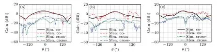
Fig.18. Radiation patterns of antenna array at different frequency points at frequency(a)2.5 GHz,(b)3.5 GHz,and(c)4.8 GHz.
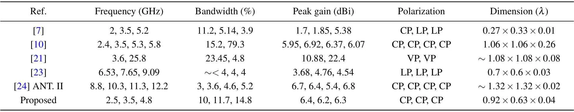
Table 2. Comparison between proposed antenna and other designed antennas reported in the literature.
Figure 18 shows the radiation patterns of antenna array at different frequency points. The measured results accord well with the simulated results and the cross-polarization is maintained at a low level. The comparison between the proposed antenna array and other designed antennas reported in the literature are given in Table 2.
4. Conclusions and perspectives
In this paper, a multi-frequency circularly polarized array based on QMSIW is proposed for sub-6 applications. The antenna array is composed of three independent sub-arrays to achieve three circularly polarized frequency bands and each of the sub-arrays employs the modified QMSIW. The stripslot is introduced to broaden the impedance bandwidth while the dimension is decreased by 75%. Four elements are assigned in the rotation order to achieve the circular polarization.Meanwhile,a metasurface is introduced to further improve the impedance bandwidth of the sub-array. The measured results accord well with the simulated results. The axial ratio bandwidth of the antenna array is wide and 220 MHz(2.46 GHz–2.68 GHz), 280 MHz (3.4 GHz–3.68 GHz), and 410 MHz(4.42 GHz–4.83 GHz) respectively. Meanwhile, the gain is stable in the operating band within uncertainty of 0.7 dBi.
Acknowledgement
Project supported by the National Natural Science Foundation of China(Grant No.61871394).
猜你喜欢
音乐天地(音乐创作版)(2022年6期)2022-10-14
杭州(2022年7期)2022-05-07
政工学刊(2021年7期)2021-07-10
少年漫画(艺术创想)(2020年4期)2020-08-24
少年漫画(艺术创想)(2020年3期)2020-07-25
学生天地(2020年25期)2020-06-01
文苑(2019年22期)2019-12-07
华人时刊(2019年23期)2019-05-21
海峡姐妹(2018年11期)2018-12-19
剑南文学(2016年11期)2016-08-22

- Chinese Physics B的其它文章
- A nonlocal Boussinesq equation: Multiple-soliton solutions and symmetry analysis
- Correlation and trust mechanism-based rumor propagation model in complex social networks
- Gauss quadrature based finite temperature Lanczos method
- Experimental realization of quantum controlled teleportation of arbitrary two-qubit state via a five-qubit entangled state
- Self-error-rejecting multipartite entanglement purification for electron systems assisted by quantum-dot spins in optical microcavities
- Pseudospin symmetric solutions of the Dirac equation with the modified Rosen–Morse potential using Nikiforov–Uvarov method and supersymmetric quantum mechanics approach