
Generation of mid-infrared supercontinuum by designing circular photonic crystal fiber
2022-05-16 07:10YingHuang黄颖HuaYang杨华andYuchengMao毛雨澄
Chinese Physics B 2022年5期
关键词:杨华
Ying Huang(黄颖) Hua Yang(杨华) and Yucheng Mao(毛雨澄)
1College of Computer Science and Electronic Engineering,Hunan University,Changsha 410082,China
2State Key Laboratory of Integrated Optoelectronics,Institute of Semiconductors,Chinese Academy of Sciences,Beijing 100083,China
Keywords: circular photonic crystal fiber,chalcogenide glass,direct soliton spectrum tunneling,nonlinearity
1. Introduction
In recent years, photonic crystal fibers (PCFs) made of the silica glass have played an important role in supercontinuum (SC) generation due to the availability of suitable pump sources and the design flexibility of dispersion.[1–3]Remarkably, silica suffers from severe infrared absorption at wavelengths beyond 2.2 μm, which makes it impossible to extend the generated SC far into the mid-infrared (MIR) region.[4]However, MIR-SC generation is an emerging research field driven by a large number of potential applications, such as spectroscopy, microscopy, frequency metrology, and remote sensing.[5–7]Specifically, PCFs made with soft glass, including chalcogenide, tellurite, and fluorite, provide a new possibility of generating the MIR-SC due to their wide transparent windows and high nonlinearities in the MIR region.[8–10]
It is worth noting that the propagation losses of tellurite and fluorite PCFs are considerably large at the wavelength beyond 5 μm while the chalcogenide glasses, especially As2S3and As2Se3,are transparent at the wavelength up to 12 μm and 15 μm respectively.[11,12]Therefore, the chalcogenide glass PCFs are excellent candidates for MIR-SC generation. As is well known, efficient and broadband MIR-SC can be obtained by pumping in the anomalous dispersion regime close to the zero-dispersion wavelength(ZDW)of fiber.[1,13]Moreover, the multiple ZDWs and high nonlinearity are usually used to extend the SC.[3,14–16]In some cases, the formation mechanism of SC can be changed or enhanced by cascading or tapering PCF,and by scaling down the fiber core size.[17–19]In fact, the position and the number of the ZDWs and the shape of the dispersion curves are so important that they are often engineered to obtain high nonlinearity and more phase matching points, thus artificially promoting the evolution of the SC.[20,21]Nevertheless, the bulk chalcogenide glass usually owns a large normal dispersion in the infrared regime,which dramatically goes against the expansion of SC.[11,13]The dispersion control becomes a very important challenge for the generation of MIR-SC in chalcogenide PCF. The essence of dispersion control is to adjust the waveguide dispersion of PCF to balance off its material dispersion,so as to obtain the ideal dispersion curve.[22,23]Recently, a new PCF design is proposed based on a circular ring structure with few layers of air holes.[24–26]In 2016,Ahmad introduced the specific design of a C-PCF with chalcogenide glass into the generation of MIR-SC for the first time.[24]Compared with other PCFs,the circular PCF (C-PCF) has more air-holes in the corresponding ring and thereby enhances the confinement performance.Based on its advantages, MIR-SC generation in the C-PCF with chalcogenide glasses under the different incident conditions is researched here.The incident parameters,for example,the propagating distance, pump power, initial chirp, and the position of ZDW,have a nonnegligible impact on the temporal and spectral evolution during the MIR-SC generation.[1,27,28]In addition, the flat dispersion was beneficial to extend the width of the SC.[29,30]So far,few researchers have combined the high nonlinearity and wide transparent window of As2Se3,the large tight-mode confinement of C-PCF, the flat dispersion curve and the three ZDWs together to generate MIR-SC.Therefore, it is significant to study the MIR-SC generation with different incident parameters in the As2Se3C-PCF with flat dispersion and 3 ZDWs.
In this paper,a C-PCF made of As2Se3is designed to have flat dispersion and 3 ZDWs. An ultra-short femtosecond (fs)pulse is injected in the first anomalous dispersion regime of the C-PCF,whose high intrinsic nonlinearity can reduce the pump power and propagating length for MIR-SC generation. The temporal and spectral variations are studied when the propagating length, initial chirp, pulse power and pulse width are varied. The most optimal conditions of MIR-SC generation are expected to be found,as well as a wide and flat SC will be developed,to support the application of MIR-SC in practice.
2. Propagation model in C-PCF
Propagation of an ultra-short pulse in C-PCF can be described by the generalized nonlinear Schr¨odinger equation(GNLSE)[29,30]
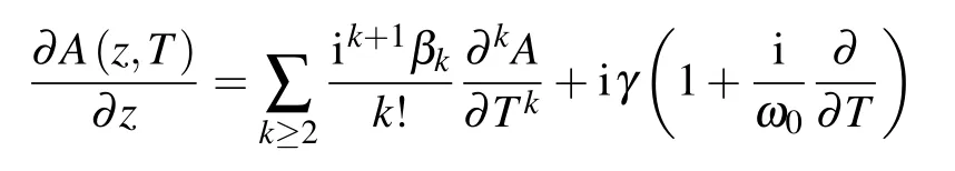
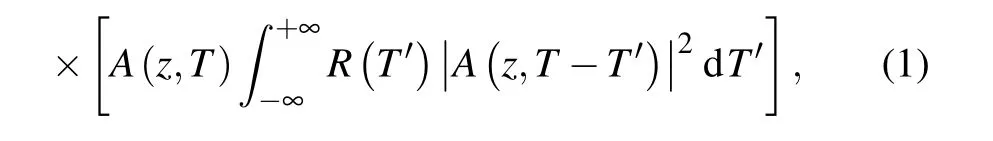
whereA(z,T) represents the slowly varying envelope of the pump pulse in a retarded time frameT,βkis thekthorder dispersion parameter at the central frequencyω0,andγis the nonlinear coefficient. The material response functionR(t)includes both the instantaneous Kerr-contribution and the delayed Raman contributionhR(t),
In the case of As2Se3glass,fR=0.100,τ1=23.1 fs, andτ2=195.0 fs. Meanwhile, the C-PCF loss is neglected since only a short length(47 mm)is used.
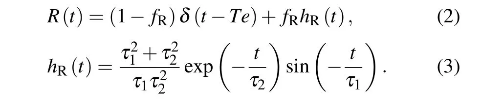
In our simulation,the hyperbolic secant pulse(T0=30 fs,50 fs,or 70 fs,λ0=4.3 μm)is assumed to act as an input pulse expressed as
Here,T0is the input pulse width,P0is the peak power of the incident pulse,andCis an initial chirp parameter.
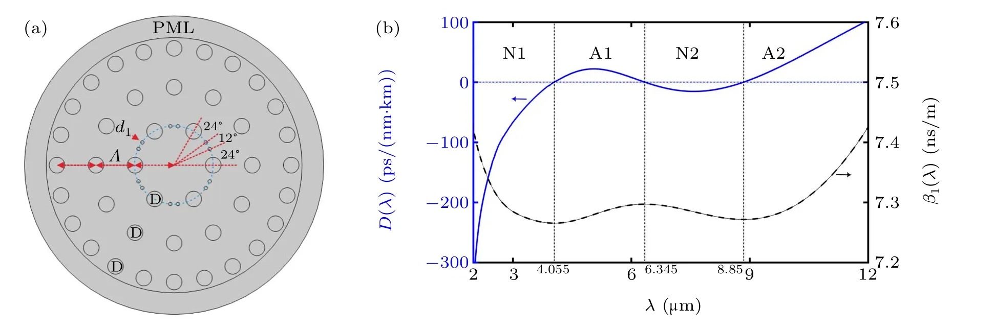
Fig.1. (a)Cross-section of C-PCF.(b)Chromatic dispersion(blue solid line)and time delay(black dash line)profiles of C-PCF.
In order to explain the influence of the three ZDWS and flat dispersion on the generation of MIR-SCs,a C-PCF,whose cross section is shown in Fig.1(a),is designed to compare the simulation results of different MIR-SCs,so as to determine the optimal pulse parameters when the propagation distance and incident pulse changed. The pitchΛis the layer-to-layer spacing, theDis the air-hole diameter of each ring, andd1is the diameter of extra small air-hole inserted between the lattices of the first ring to control the third ZDW.The outermost layer of C-PCF is the perfectly matching layer(PML)used to eliminate optical reflecting at the boundary. To design a C-PCF with flat chromatic dispersion,Λshould be carefully selected to control the dynamic range of waveguide dispersion,and the filling fractionD/Λshould be small enough to ensure the characteristic of single mode transmission and the first two ZDWs. Finally,the designed C-PCF has the structure parameters asΛ=4.5 μm,D=1.8 μm,andd1=0.2 μm.When the pump wavelength is at 4.3 μm, its corresponding nonlinear coefficient isγ=1122 W-1·km-1, and the high-order dispersion coefficients of the Taylor expansion areβ2=-85.8667 ps2/km,β3=3.5956 ps3/km,β4=-0.0196 ps4/km,β5=-9.0777×10-4ps5/km,β6=2.8896×10-5ps6/km,β7=-1.4942×10-7ps7/km,β8=-9.6724×10-9ps8/km,β9=2.8269×10-10ps9/km,β10=-3.8051×10-12ps10/km,β11=2.7390×10-14ps11/km,β12=-8.5436×10-17ps12/km,β13=-4.5969×10-21ps13/km, respectively. Figure 1(b)shows the profiles of chromatic dispersion and time delay of the designed C-PCF.The blue solid line shows a wide and flat dispersion less than 22.03 ps/(nm·km) at a wavelength range from 3.53 μm to 9.65 μm,and 3 ZDWs located at 4.055 μm,6.345 μm, and 8.85 μm respectively. The three ZDWs divide the dispersion curve into four regions, which are named N1,A1,N2,and A2 from short-to-long wavelengths. N1 and N2 are the first and second normal dispersion regimes,respectively, while A1 and A2 are the first and second anomalous dispersion regimes, respectively. The black dash line represents the time-delay curve of C-PCF, which allows, at most,four frequency components to propagate at the same speed.
3. Numerical results in C-PCF
In this section, we present numerical results to illustrate the MIR-SC generation when pumping the femtosecond pulses in the anomalous dispersion regime of C-PCF. At the same time, temporal and spectral characteristics of MIR-SC are studied in detail under the different incident pulse conditions of propagating distances, the initial chirp value, pump energy,and pulse width. Here,all intensity plots using a logarithmic scale are truncated at-40 dB relative to the maximum value.
3.1. Evolution of MIR-SC as the distances vary
A MIR-SC is firstly obtained by launching an unchirped 50 fs pump pulse with 4000 W peak power into the C-PCF with a length of 466 mm.In the femtosecond regime,MIR-SC generation by pumping in the anomalous dispersion regime is dominated by soliton-related dynamics. Figures 2(a)and 2(b)show the pulse evolution in the whole 466 mm propagation length.Figure 2(b)shows a new soliton is formed and centered at the wavelength of around 10 μm. Figure 2(c)is the output spectrogram of incident pulse and shows the coexistence of broad-band MIR-SC spectrum and some narrow-band oscillations. So,it is necessary to make the whole evolution process of the incident pulse in C-PCF clear and to obtain the real flat and wide MIR-SC.

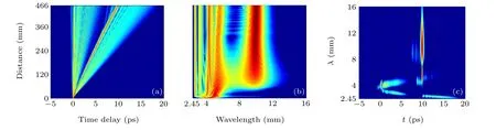
Fig.2. (a)Temporal and(b)spectral evolution of unchirped fs pulse with 4000 W peak power in PCF.(c)Spectrogram at the fiber length of 466 mm.
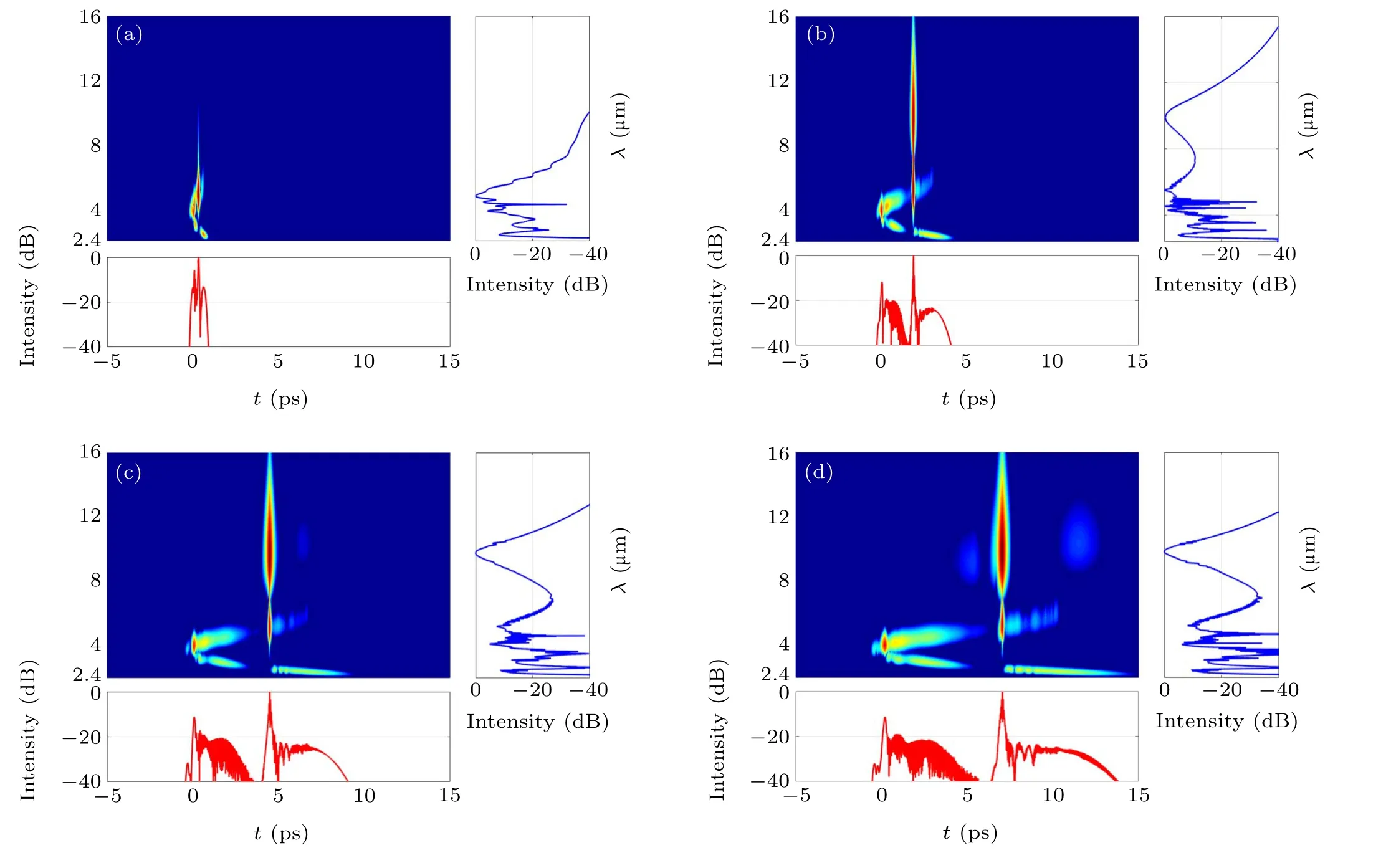
Fig.3. The output spectrograms of the incident pulse with 4000 W peak power at different propagating distances of(a)32 mm,(b)111 mm,(c)233 mm,and(d)349 mm along PCF.
Figure 3 shows the spectrograms at different propagating distances. Figure 3(a)shows the first fundamental soliton centered at a wavelength of 5.16 μm becomes asymmetric in the spectral domain at the propagation distance of 32 mm. Figure 1(b) shows the main reason of spectral asymmetry is the mismatch between the SPM and gradually decreasing chromatic dispersion on long wavelengths side of the first fundamental soliton. Therefore,under the dominant action of SPM,the first fundamental soliton is compressed in the time domain and broadened in the frequency domain. Due to pulse internal Raman scattering, part of the energy of the fundamental soliton shifts from the short wavelength side to the long wavelength side, and its spectrum becomes asymmetrical. As the propagating length increases, the first fundamental soliton is greatly compressed. At the same time, the spectrum is extended to cover part of the first anomalous dispersion region(A1), all the second normal dispersion region (N2) and part of the second anomalous dispersion region (A2). With the first fundamental soliton red-shifted continuously,its energy is transferred to the A2 step by step, rather than to R-DW.That is also the root origin of DSST. Figure 3(b) shows the peak powers of the first fundamental soliton and the DSST soliton are same at the propagation distance of 111 mm, it is easy to see the MIR-SC spanning a wider band from 2.578 μm to 15.36 μm. Figure 3(c) shows most energy of the first fundamental soliton has been transferred to the DSST soliton,which destroys the flatness of MIR-SC.Also,a weak optical shocking happens in the DSST soliton due to its narrow time span and huge pulse energy, which can produce new stronger frequency components in the red-end than that of the blue-end and make the spectrum of the DSST soliton more asymmetric.Figure 3(d) obviously shows new stronger frequency components on both blue-and red-ends of the spectrum of the DSST soliton,and the intensity of new frequency components on the red-end is stronger than that of the blue-end, which further identifies the exist of optical shocking. In addition, FWM is beginning to take its effect between the first fundamental soliton and DSST soliton.The new frequency components formed on the short wavelength sides of two solitons through FWM are located on left side of two solitons,which are for the reason of their smaller time delay than corresponding solitons.All of these new frequencies either degenerate the flatness of the MIR-SC or go against the extension toward the red end of the MIR-SC. Thus, selecting the proper propagation distance as 111 mm will avoid the optical shocking and FWM, which is beneficial to generate MIR-SC.
Figure 4 shows the detailed spectra in different locations along the C-PCF. It is easy to see how the spectrum evolves into a broadband MIR-SC, and then shrinks into a narrower one step-by-step. Before the length of 5 mm, it is SPM that expands the spectrum. After that, the main physical mechanisms are SF and B-DWs. At the length of 23 mm, two solitons and two branches of B-DWs can be observed. Then the SSFS of the first and second fundamental solitons are demonstrated along the dash arrow line and the dot arrow line respectively. Accordingly,some new frequency components are radiated into the two branches of B-DWs as the 2 fundamental solitons adjust themselves. At the length of 32 mm, we can see very little energy is transferred to the A2, which means the DSST has already taken effect. As the pulse moves forward, more energy is transferred to the A2 to form a new DSST soliton centered at the wavelength of 10 μm, a wide and flat MIR-SC is generated at the fiber length of 111 mm,while the R-DWs do not appear in the whole process. Afterwards,an optical shocking is observed to shrink the spectrum of DSST soliton toward the shorter wavelength side. At the fiber length of 466 mm,the spectrum of DSST soliton is shortened toward the short wavelength side again due to the FWM effect between the first fundamental soliton and DSST soliton.It should be noticed that the DSST soliton also moves slowly toward long wavelength side of A2 due to the SSFS.Thus,as the incident pulse propagates along the C-PCF,its spectrum is firstly extended and then shrunk. The DSST is mainly responsible for the spectrum extension at the long wavelength side in the MIR region. There is an optimal propagating distance which allows the existence of a wide and flat MIR-SC.
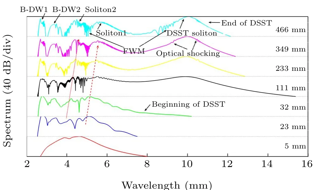
Fig. 4. Spectra evolution of the incident pulse with different propagating distances.
3.2. Evolution of MIR-SC as the initial chirp varying
In Fig. 5, we study the influence of the initial chirp on MIR-SC generation by choosing the different initial chirp value. In the time domain,the incident pulse with initial negative chirp is broadened directly at a low speed as Fig. 5(a1)shows, while the incident pulse with initial positive chirp is first compressed and then broadened at a high speed as Fig. 5(a2) shows. In the frequency domain, the incident pulse with negative chirp undergoes firstly narrowing and ultimately broadening as Fig. 5(b1) shows, while the incident pulse with positive chirp is directly broadened to a very large extent as Fig.5(b2)shows. Therefore,positive chirp can make the spectrum expand at a larger rate compared with negative chirp in the early propagating phase, which can accelerate the emergence of soliton fission. When the incident pulse attains its maximum bandwidth by SPM, fundamental solitons are ejected from the high-order soliton because of Raman effects and the corresponding B-DWs are radiated from the redshifted fundamental solitons because of higher-order dispersion effects. Afterwards, the first fundamental soliton begins to tunnel through the N2 owing to the DSST mechanism. By comparing among these figures in Fig. 5, positive chirp can make more energy transfer to first fundamental soliton and suppress the generation of the second fundamental soliton.Thus, only one branch of strong B-DW is generated by the first fundamental soliton, which expands the blue-end MIRSC.Both the B-DW and the DSST soliton appear at very short propagating distance,and more energy is transferred to DSST soliton in the same transmission distance.
To better illustrate the impact of initial chirp on MIR-SC generation,output spectrograms with different chirp values are demonstrated in Fig. 6. In the fs regime, soliton-related dynamics play an important role in the generation of SCs. Obviously,as the initial chirp changes from negative to positive,the whole output spectrum takes great changes. Figure 6(a)shows us the negative chirp can make less energy transferred to first fundamental soliton and accelerate the generation of the second and even third fundamental solitons. Thus, two branches of weak B-DWs are generated by the first and second fundamental solitons, which is not beneficial to the extension of MIR-SC toward the blue-end. Both the B-DW and the DSST soliton appear at very long propagating distance.Less energy is transferred to DSST soliton and B-DW in the same transmission distance,which will also go against the flatness of MIR-SC generation in both the red-and blue-end. The FWM between the first fundamental and DSST solitons will be suppressed compared with zero initial chirp, also, the optical shocking is absent for less energy in the DSST soliton.The spectrum of this situation is not even and wide due to the weakness of first fundamental soliton, DSST soliton and the first branch of B-DW.In contrast,figure 6(c)shows us the positive chirp can make more energy transferred to the first fundamental soliton and DSST soliton in a short distance. Even the formation of the second fundamental soliton is suppressed.Therefore,FWM and optical shocking will take place and substantially limit the spectrum extension toward the red-end. On the other hand, the strong first fundamental soliton will also bring strong B-DW, which makes the blue-end MIR-SC uneven. Meanwhile,figure 6(b)shows us the zero initial chirp is optimal among these three situations. Two fundamental solitons are radiated from the compressed incident pulse through SF, then, the energy of the stronger first fundamental soliton is distributed evenly between itself and DSST soliton,neither FWM nor optical shocking appears,which make the spectrum extend easily to deep MIR.And the second fundamental soliton also contributes to the flatness of the blue-end of MIR-SC by radiating the second branch of B-DW.So,C=0 is the best choice for MIR-SC generation.
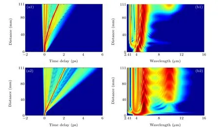
Fig.5. (a)Temporal and(b)spectral evolution of fs pulse with 4000 W peak power and initial chirp(upper figures:C=-2;lower figures:C=2)in C-PCF.
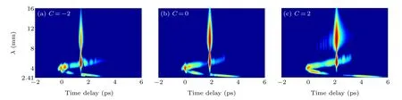
Fig.6. Output spectrograms of fs pulse with 4000 W peak power and different initial chirp values((a)C=-2;(b)C=0;(c)C=2)in C-PCF.
3.3. Evolution of MIR-SC as the power varying
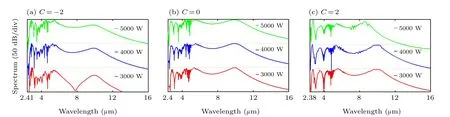
Fig. 7. The output spectra of fs pulse with the different peak power and initial chirp in C-PCF. The peak power changes every 1000 W from 3000 W to 5000 W(from bottom to top). (a)C=-2;(b)C=0;(c)C=2.
3.4. Evolution of MIR-SC as the pulse width varying
The width of the incident pulse in the time domain is inversely proportional to its width in frequency domain, thus,a narrower pulse has a wider spectrum. Figure 8 shows the evolutions of MIR-SC with different pulse widths in C-PCF.When the temporal width of the incident pulse is 70 fs, the corresponding output spectrum has a narrow spectrum width and a poor flatness. As the temporal width of the incident pulse decreases with a step size of 20 fs, the width and flatness of the output spectrum will be improved gradually. When the width of the incident pulse is reduced to 30 fs and its most optimal propagating distance is 47 mm, the width of the output spectrum covers 2.535 μm–16.6 μm, and the flatness of that is better than that of another two incident pulses. The key reason can be explained as the formation of MIR-SC covering 4.96 μm–16.6 μm depends heavily on the process of SSFS of the first fundamental soliton and spectrum-tunneling of DSST soliton. In the time domain, the narrower the input pulse is,the narrower the first fundamental-order soliton will be. With the dispersion decreasing,the mismatch between the SPM and dispersion begins to dominate, the narrower first fundamental soliton is easier to be compressed in the time domain than the wider one, and it is easier to expand in the frequency domain,where eventually a greater soliton-tunneling bandwidth is obtained. During the process of DSST, the narrower first fundamental soliton in time-domain constantly transfers its energy to the DSST soliton,at the 47 mm propagating length,its whole energy will be more evenly distributed throughout the MIR-SC. While the SPM, SF and B-DW are responsible for the MIR-SC covering 2.535 μm–4.96 μm. Compared with the pulse widths of 50 fs and 70 fs,it is obvious that the pulse of 30 fs induces only a strong first fundamental soliton, which pits the spectrum between the first fundamental soliton and its B-DW.Thus, we should make a balance on both red-end and blue-end of the MIR-SC when choosing the width of the pulse.
On the basis of obtaining the widest MIR-SC, different random noises are added to evaluate the stability of the simulation when the ratio of noise-to-signal amplitude is 0,0.001,and 0.008, respectively. The details of spectra are listed in Fig.9.
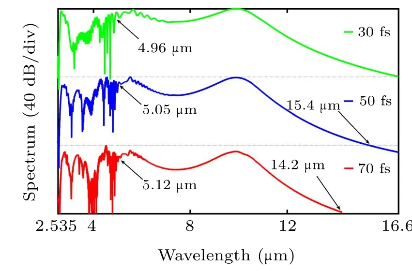
Fig.8.The output spectra of different fs pulse with fixed 4000 W peak power at the most optimal propagating distance in C-PCF.The pulse width changes every 20 fs from 30 fs to 70 fs(from top to bottom).
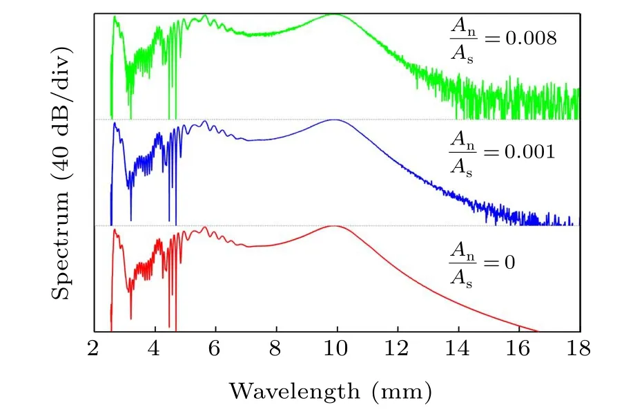
Fig.9. Spectra evolution with the amplitudes ratios of random noises to signals equal 0,0.001,and 0.008(from bottom to top).
TheAnandAsin Fig. 9 are the mean amplitudes of noise and signal respectively. Figure 9 shows the influence of random noise on spectrum evolution as the ratio of noise amplitude to signal amplitude increases, the shape of the spectrum remains unchanged, but the quality of the spectrum gradually decreases. This is due to the modulation instability(MI)caused by the interaction of dispersion and Kerr nonlinear when the incident optical pulse propagates in the anomalous dispersion region. When the frequency of random noise is within the range of the MI gain spectrum, it will be exponentially amplified, and MI will cause significant fluctuation of MIR-SC.In order to obtain high-quality MIR-SC,it is best to keep the amplitude ratio of the noise to the signal as low as possible.
3.5. Comparison with reported C-PCF
Compared with other reported C-PCF listed in Table 1,the C-PCF proposed in this paper generates the widest MIRSC covering more than 14 μm. Compared with Ref.[24],our C-PCF has three ZDWs and a wide flat region in the dispersion curve,and a medium nonlinearity,which makes the DSST possible. The first ZDW of our C-PCF is down-shifted to around 4 μm,which allows the pump source centered at proper wavelength and easily extends the MIR-SC toward both shortand long-wavelength sides. In Ref.[24],the dispersion curve of PCF has a wider first anomalous dispersion region (A1),which requires more pumping power to push the SSFS and RDW spectra to the longer wavelength side. Compared with Ref. [25], the As2Se3-based C-PCF proposed in this paper greatly expands MIR-SC within a shorter fiber length due to its higher nonlinear coefficient and wider transparent window against a silica-based one. Compared with Ref.[26],the proposed C-PCF here has three ZDWs and the expansion mechanism of MIR-SC is soliton dynamics, while Ref. [26] suggested an all-normal dispersion(ANDi)and generated coherent MIR-SC through SPM and OWB. Furthermore, the temporal width of the pump source in this work is 30 fs,which is conductive to the expansion of MIR-SC.
4. Conclusion
By customizing the C-PCF with flat chromatic dispersion and three ZDWs,the widest MIR-SC spanning from 2.535 μm to 16.6 μm can be obtained at small propagating length of 47 mm due to the As2Se3’s intrinsic wide transparent window and high nonlinearity. The formation of MIR-SC is dominated by the SSFS and DSST on the long wavelength side and by SPM, SF and B-DW on the short wavelength side. The mismatch between the SPM and gradually decreasing chromatic dispersion induces the DSST, which transfers the energy of the first fundamental soliton to DSST soliton gradually and prevents the R-DW’s formation. By changing the initial chirp,peak power, and time-domain width of the incident pulse, it is found that the zero-initial chirp, proper pulse peak power(4000 W),and proper narrow pulse width(30 fs)are more beneficial to prevent the presence of optical shocking and FWM,and finally increase the range and flatness of the MIR-SC. In addition, in order to reduce the influence of MI on MIR-SC,the amplitude ratio of noise to the signal should be controlled as low as possible. These numerical results are of great significance as they point out how to control the long-and shortwavelength side of MIR-SC by different propagating distances and pulse parameters.
Acknowledgments
Project supported by the National Natural Science Foundation of China(Grant No.61275137)and the Opened Fund of the State Key Laboratory of Integrated Optoelectronics(Grant No.IOSKL2020KF20).
猜你喜欢
金山(2022年6期)2022-06-24
科学家(2022年5期)2022-05-13
电影文学(2021年6期)2021-11-14
检察风云(2018年18期)2018-10-16
中国医药导报(2018年16期)2018-09-25
当代党员(2018年24期)2018-01-22
百姓生活(2017年11期)2017-11-14
理科考试研究·高中(2016年10期)2017-01-17
新青年(2016年7期)2016-07-05
浙江人大(2016年7期)2016-05-14

- Chinese Physics B的其它文章
- A nonlocal Boussinesq equation: Multiple-soliton solutions and symmetry analysis
- Correlation and trust mechanism-based rumor propagation model in complex social networks
- Gauss quadrature based finite temperature Lanczos method
- Experimental realization of quantum controlled teleportation of arbitrary two-qubit state via a five-qubit entangled state
- Self-error-rejecting multipartite entanglement purification for electron systems assisted by quantum-dot spins in optical microcavities
- Pseudospin symmetric solutions of the Dirac equation with the modified Rosen–Morse potential using Nikiforov–Uvarov method and supersymmetric quantum mechanics approach