
Parity–time symmetric acoustic system constructed by piezoelectric composite plates with active external circuits
2022-06-29 08:55YangZhou周扬ZhangZhaoYang杨彰昭YaoYinPeng彭尧吟andXinYeZou邹欣晔
Chinese Physics B 2022年6期
关键词:周扬
Yang Zhou(周扬) Zhang-Zhao Yang(杨彰昭) Yao-Yin Peng(彭尧吟) and Xin-Ye Zou(邹欣晔)
1Key Laboratory of Modern Acoustics,MOE,Institute of Acoustics,Department of Physics,Collaborative Innovation Center of Advanced Microstructures,Nanjing University,Nanjing 210093,China
2State Key Laboratory of Acoustics,Chinese Academy of Sciences,Beijing 100190,China
Keywords: parity-time symmetry,acoustic gain material,piezoelectric composite plate,exceptional point
1. Introduction
Parity–time (PT) symmetry, or space–time reflection symmetry, initially proposed in quantum mechanics by Bender,[1,2]reveals that the quantum systems with non-Hermitian Hamiltonians can still host a real spectrum corresponding to observable physical quantities when they satisfy PT symmetry. After being introduced into optics,[3]PT symmetry has been extensively investigated on the experimental implementation and properties demonstration in the classical wave systems, such as unidirectional zero reflection,[4,5]coherent perfect absorption,[6–8]asymmetric mode conversion,[9,10]power oscillations of light propagation[11]and single-mode laser.[12–14]In the meantime,PT-symmetric acoustics[15]also has attracted intense attention after being proposed by Zhuet al.Since it is difficult to find the natural gain material in acoustics,[16]passive PT-symmetric systems[17–19]that consist of purely dissipative elements inspire the diverse designs of the acoustic PTsymmetric system. Moreover,the intriguing effects of exceptional points (EPs) corresponding to the PT phase transition points can also be observed in a passive PT-symmetric system,such as unidirectional invisibility,[20–24]anomalous reflection and refraction,[25–28]unidirectional sound focusing effect,[29]acoustic negative refraction[30]and sound absorption.[31]However,it is still difficult to construct a gain part for an active PT symmetry in the acoustic system,as the gain parts reported always consist of properly controlled loudspeakers,[32,33]interdigital transducers,[34]etc.
Meanwhile,the piezoelectric composite material[35,36]is widely used in many fields as it is a kind of low-cost but practical transducer. The most commonly used composite material consists of a copper baseplate and a piezoelectric ceramic piece attached to the baseplate. It always can be lumped into idealized discrete elements because it is thin enough and the diameter is much smaller than the acoustic wavelength of the frequency interested.[37,38]Then, the piezoelectric composite material with an external circuit can be easily analyzed with the lumped element model.[39]It can be found that the composite material can perform as a negative impedance device with specific external circuits,that is,we can synthesize a kind of gain material into the acoustic field by adjusting the external circuits connected to the piezoelectric composite material.
In this paper,we present an acoustic active PT-symmetric system constructed by a pair of piezoelectric composite plates that are loaded at the side wall of the waveguide with suitably tailored external electrical circuits. Two identical piezoelectric composite plates are controlled by independent external electrical circuits,respectively,which can provide the desired positive or negative resistances. Crucially,the EPs with unidirectional transparency can also be exactly induced in the presented structure. Meanwhile,the PT-broken phases as well as the reverse of the direction of acoustic transparency can be directly observed by adjusting the distance between the gain and loss parts. Our results are expected to open a different route for acoustic wave control and synthesis of EPs.
2. Theoretical analysis
The structure of the designed PT-symmetric system is shown in Fig. 1. Here, a gain part and a loss part with settled distanceLare placed on the same side of the airborne tube with hard-wall boundaries. The cross-sectional area of the main tube isSm, and the area of the gain (loss) part isSa(Sb). The acoustic pressure and the corresponding velocity of the incident wave and the transmitted wave are (p-,v-) and(p+,v+), respectively. The air density and speed of acoustic wave areρ0andc0in the tube, respectively. To construct an acoustic PT-symmetric system that satisfies the fundamental relation(PT)S(ω*)(PT)=S-1(ω),[40]where the operatorPrepresents parity reflection,the operatorTrepresents time reversal andSis the scattering matrix of the system,respectively.We take the relationship for the acoustic pressures and velocities of the incident and transmitted waves into consideration because the system can be described as a standard two-port network model,which can be written as
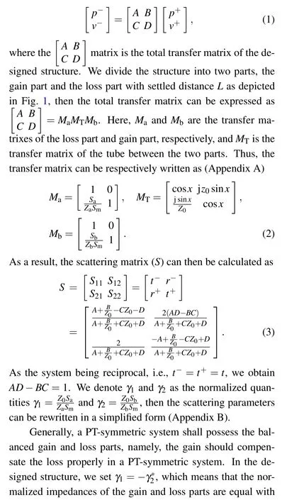
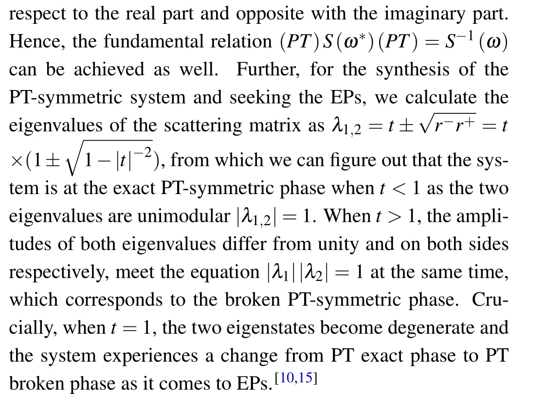
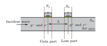
Fig.1. Schematic of the designed PT-symmetric system.
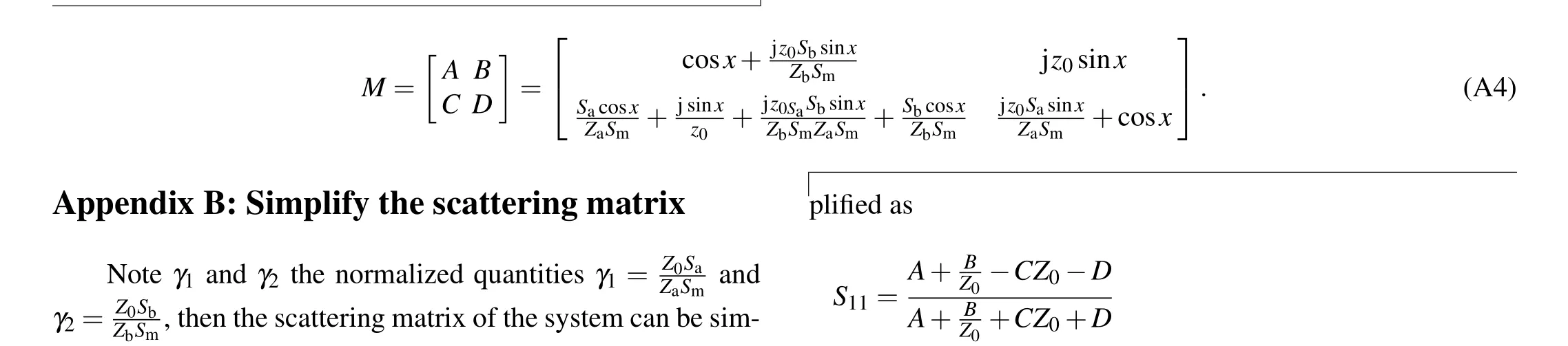
As quantum EPs designed by engineering the Hamiltonian matrix, acoustic EPs can be achieved by manipulating the elements in the corresponding scattering matrix. The system will be in a unidirectional invisible state when it is at EPs, which corresponds toS11=0 whenγ1=-γ2=2 (Appendix B).In this case,the reflection from the left is zero while it is non-zero from the right. We can substituteγ1=-γ2=γ(γis real number)into Eq.(3),and obtain the relation as presented in Fig. 2(a). Here,x=k0Lis the acoustic separation length between the gain and loss parts,we setx=arcsin(3/5)as the choice ofxvalue does not make much difference to the shapes of the curves. As we can see, only whenγ=2,the reflection coefficient from the left comes to zero while the reflection coefficient from the other side is non-zero. And the transmission coefficients from both sides are unity at the point.It means thatγ=2 is the particular situation where the system is at EPs with arbitraryx.
Then we consider another nonspecial situationγ=1+j.The scattering parameters are shown in Fig.2(b)with different values ofx. There are two different zero points atx=0.463 andx=1.571 corresponding to zero reflection coefficient from left and right, respectively. Whenx=0.463, the reflection from the side of loss part is zero. And whenx=1.571, the reflection from the side of gain part is zero. That is to say,the reversal of the direction of the unidirectional invisibility can be found by turning the distance between the two parts. The transmission coefficients at these points have the unity absolute value while the absolute values of the eigenvalues are at the tipping points,for eigenvalues degenerate or not as can be seen in Fig. 2(c). It means that the two points are both EPs here and the system is at the PT-broken phase whenxdiffers from 0.463 to 1.571.
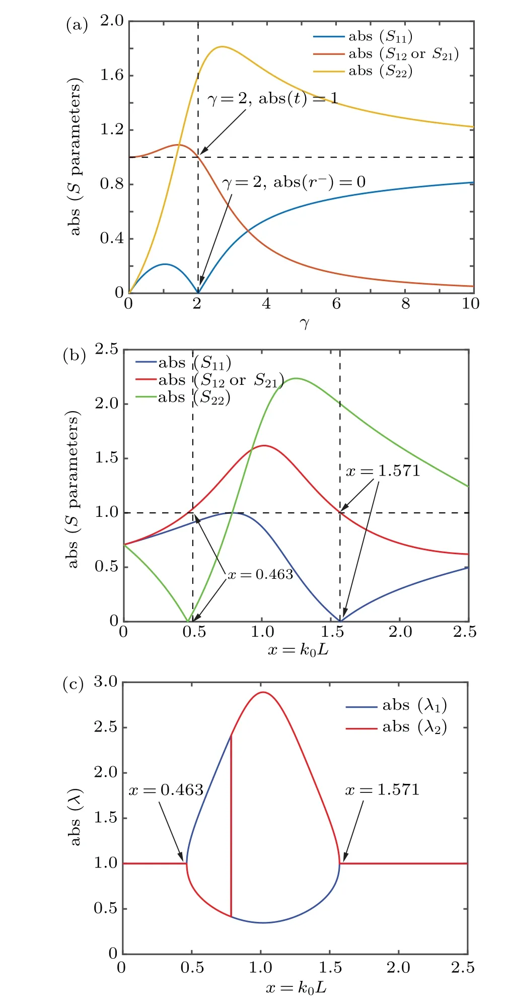
Fig.2. Theoretical results of the scattering parameters and eigenvalues of the scattering matrix.(a)Scattering parameters with different γ when x=arcsin(3/5). Only one EP at γ=2 where S11=0 and abs(S12)=1(‘abs’means absolute value). (b)Scattering parameters with different x when γ=1+j. (c)Eigenvalues of the scattering matrix with different x when γ =1+j. The two eigenvalues begin to split when x=0.463 and degenerate again when x=1.571. Both the two points are EPs.
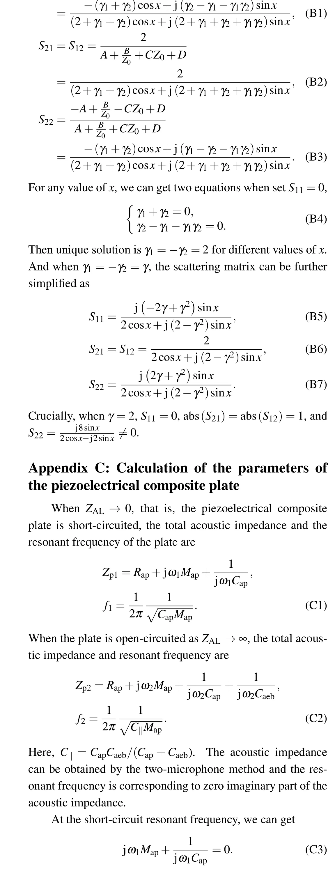
To obtain the required normalized acoustic impedance for the gain and loss side branches, the piezoelectric composite plate with an external circuit is introduced. As shown in Fig. 3(a), there is a short tube with the piezoelectric composite plate covering the opening. The tube is used to ensure the external environment of the piezoelectric composite plate. Therefore,the acoustic impedance of this structure can be obtained as the sum of the piezoelectric composite plate and the tube asZsum=Zplate+Ztube. Here, if we consider the end as acoustic hard-wall boundary,Ztubecan be calculated directly by using the impedance transfer equation asZtube≈-jρ0c0cot(kh),wherehis the length of the tube.
As for the piezoelectric composite plate [Fig. 3(a), right panel], it consists of a piece of copper as baseplate and a piece of PZT-5H (with aluminized surface) attached to the middle of the upper surface of the baseplate. We consider that the thickness of the aluminum film is negligible. The radius and thickness of the PZT-5H are Thk1=0.21 mm and Rad1=9.5 mm, respectively. The dimensions of the copper baseplate are Thk2=0.13 mm and Rad2=13.5 mm,respectively. Considering that the dimensions of the plate are much smaller than the wavelengths of the interesting frequencies,the composite plate can thus be lumped into idealized discrete circuit elements around the resonant frequency as illustrated in Fig. 3(b). It can be lumped into two parts: the first part is described as the acoustic domain that includes the acoustic resistanceRap,acoustic massMapand the short-circuit acoustic complianceCapof the piezoelectric composite plate; the second part is described as the electrical domain that includes the blocked electrical capacitanceCebof the piezoelectric diaphragm and the external electrical load impedanceZelacross the piezoelectric composite plate.Between the two parts,there is an approximate lossless transformer with the turn ratioφthat converts energy between the two domains. Therefore,the blocked electrical capacitance and electrical impedance can be transformed to acoustic domain asCaeb=Ceb/φ2andZal=φ2Zel. As a result, we can obtain the simplified equivalent circuit representation by the pure acoustic impedance as shown in Fig. 3(c), and the total acoustic impedance of the plate is given by

whereω=2π fis the angular frequency when the operating frequency isf. The acoustic impedance of a piezoelectric composite plate is determined once made, while it is feasible to change the whole equivalent acoustic impedance by adjusting the impedance of the external circuit. Thus,active control can be introduced, and we can synthesize the gain part and loss part by linking the negative or positive impedance circuit to the piezoelectric composite plates. To begin with, we should measure the parameters of the piezoelectric composite plate. Here,we put forward a method to determine all the parameters of a piezoelectric composite plate around the resonant frequency by measuring the short-circuit resonant frequency(f1),the open-circuit resonant frequency(f2),and the impedance of the plate with short-circuit external circuit at the open-circuit resonant frequency(Zp0,the real part ofZp0noted asZp01, andZp02for the imaginary part). The parameters of the piezoelectric composite plate can be obtained from the following equations(Appendix C):
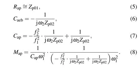
Here,ω1=2π f1andω2=2π f2. This method has no need to carefully measure the transverse displacement of the whole plate as the traditional method,[37–39]in which it is hard to measure the lateral displacement accurately and deduce these parameters by integrating with respect to the displacement.
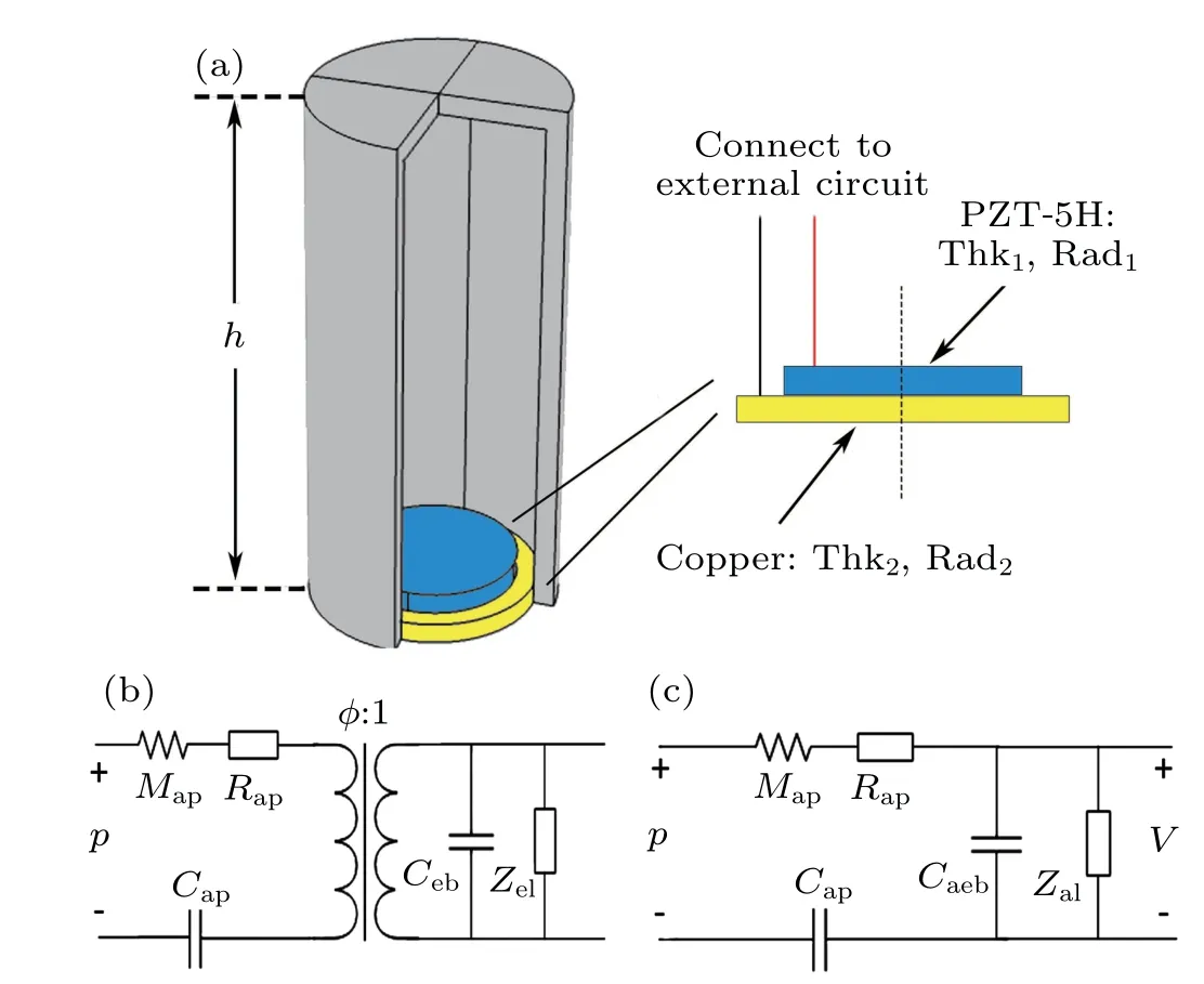
Fig.3. (a)Schematic of a single part loaded at the side of waveguide.(b)Lumped element model of a piezoelectric composite plate with the external circuit load Zel. (c)Acoustics analogy circuit diagram to(b)as the electrical domain can transfer to acoustic domain by the transformer with Caeb=Ceb/φ2 and Zal=Zelφ2.
3. Computational results
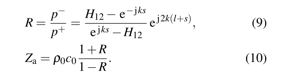
The acoustic impedances and the reflection coefficients of the piezoelectric composite plate can be obtained from the two-microphone method (TMM).[41]The illustration of the TMM is shown in Fig. 4(a). The distance between the two microphones iss,the distance from the surface of the measuring structure to the nearest microphone isl,and the frequency response function between Mic. 1 and Mic. 2 isH12. Here,the frequency response can also be expressed as the ratio of the complex pressure at Mic. 2 to the complex pressure at Mic. 1.We assume that the effects of tube attenuation and viscosity are negligible,and only plane wave propagates along the tube,then the complex reflection coefficient at the sample surface and its acoustic impedance can be given by
Then, the acoustic impedances of the piezoelectric composite plate at different frequencies and its resonant frequencies with open or short external circuit can be obtained.With the dimensions proposed above, we get the two resonant frequenciesf1=1755.9 Hz andf2=1874.2 Hz from Figs. 4(b)–4(e). It can be seen that the imaginary part of the specific acoustic impedance comes to zero and the absolute value of the reflection coefficient reaches the minimum value, which agrees well with the theory. And we can getZp0=765882.2+j·9632156.2 kg/(m4·s) further. Then, the parameters of the piezoelectric composite plate (Rap,Caeb,Cap,Map) can be obtained (Appendix C). However, the turn ratioφis necessary if we want to design the external circuits for different required equivalent acoustic impedance.We choosef3= 1800 Hz to calculate it. When the plate is shorted-circuited, the corresponding acoustic impedance isZa1=765917+j·3652139 kg/(m4·s). Further, we load the plate withZel0=1000 Ω and then the acoustic impedance isZa2=3989143.5+j·2441532.5 kg/(m4·s). Thus, the turn ratioφcan be obtained by
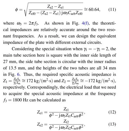
whereZti=Zi/sa-Za1-Ztube. Since that the electrical load can be expressed asZe=Re0+jω3Me0, the external circuits are then deduced from the relations shown before and can be presented as resistances and inductances asRe0p=-255.74 Ω,Me0p=-98.91 mH for the passive plate andRe0a=-548.72 Ω,Me0a=-93.07 mH for the active plate,respectively. To obtain the negative impedance and inductance,a non-foster circuit is used here as shown in Fig. 5(a). the negative impedance is implemented by an operational amplifier with feedback resistors,and the corresponding equivalent circuit diagram is shown in Fig. 5(b). The effective negative electric impedance at the connector is
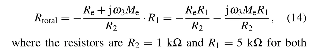
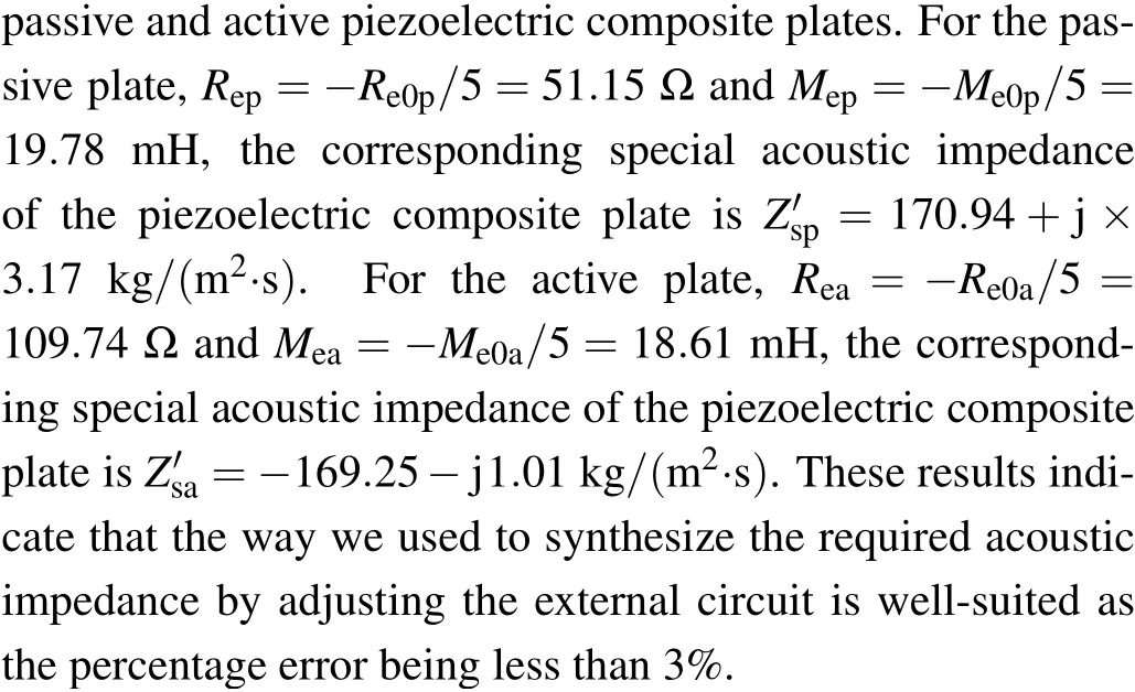
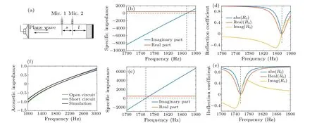
Fig. 4. (a) Schematic of the two-microphone method. (b) Specific acoustic impedance near the resonant frequency when the piezoelectric composite plate is open-circuited. (c)Specific acoustic impedance near the resonant frequency when the plate is short-circuited. (d)Reflection coefficient when the plate is open-circuited. (e)Reflection coefficient when the plate is short-circuited. (f)Acoustic impedances of the plate acquired by calculating with the lumped elements.
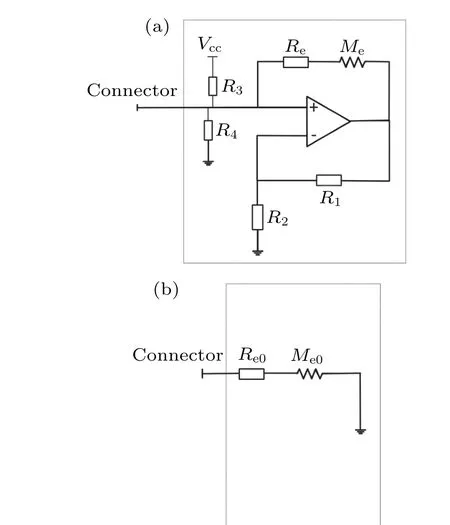
Fig.5. (a)The electronic schematic for external circuits. The resistors R3 and R4 provide the input bias of Vcc/2 at the positive input of the amplifier. Specifically,R3=R4=100 kΩ,R2=1 kΩ,R1=5 kΩ. (b)Equivalent circuit schematic of the circuit,Re0=-5Re,Me0=-5Me.
Further, we combine the passive part and active part for the synthesis of the EP in PT-symmetric system as shown in Fig. 1. The active part is connected to the external circuit as presented in Fig. 5(a) withRea=51.15 Ω andMea=19.78 mH,while the passive part is connected to the same circuit withRep=109.74 Ω andMep=18.61 mH.And the corresponding acoustic pressure fields of distributions are depicted in Fig. 6. It is clear that the reflected acoustic wave nearly vanishes when the acoustic wave comes from the left of loss part. On the contrary, the reflection coefficient is relatively large when the acoustic wave comes from the right of gain part. These results indicate that the presented PT-symmetric system and the corresponding EPs are consistent with the calculation results and fairly accurate.
Then, we chooseγ= 1-j as an example for the nonspecial situation, which corresponds toZ1= 172-172j kg/(m2·s) andZ2=-172-172j kg/(m2·s). All the other parameters are as the same as the sample discussed above,and we can synthesize the special acoustic impedances directly by merely turningReandMe. In this case, the passive part is connected to the external circuit withRep=-(280.16/5) Ω = 56.03 Ω andMep=-(115.4/5) mH =23.08 mH, while the active part is connected to the same circuit withRea=124.0 Ω andMea=21.52 mH. The measured special acoustic impedance of passive part isZ′sp=169.23-177.43j kg/(m2·s), andZ′sa=-169.03-172.30j kg/(m2·s)for the active part. Crucially,the percentage error here is less than 3%as well. Then we combine the passive part and active part for the synthesis of the EP as shown in Fig.7.Here we setx=1.57 which is corresponding to the unidirectional transparent point for the wave coming from the left of loss part.The actual reflection coefficient is 0.134 in simulation which is much larger than the coefficient obtained from the particular situationγ=2 as the deviation of the distanceLand the normalized quantityγboth influence the result.
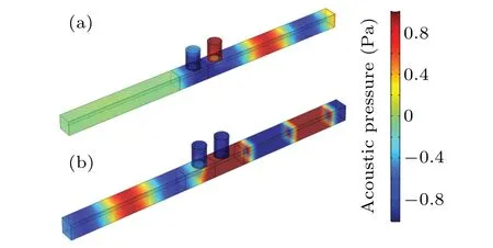
Fig. 6. The γ =2 is fulfilled thus the system is at EPs with arbitrary value of L,and x=1.7 is chosen as an example. (a)Scattering acoustic pressure when the input is coming from the left of loss part. The reflection coefficient here is 0.024 and the frequency of acoustic waves is f3=1800 Hz.(b)Scattering acoustic pressure when the input is coming from the right of gain part.
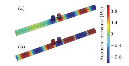
Fig.7. The γ=1-j and the system is at EPs when x=1.571 or 2.687,and x=1.571 is chosen as an example. (a)Scattering acoustic pressure when input is coming from the left of loss part. The reflection coefficient here is 0.134 and the frequency of acoustic waves is f3=1800 Hz.(b)Scattering acoustic pressure when input is coming from the right of gain part.
4. Discussion and conclusion
In summary, we have designed an active-controlled acoustic PT-symmetric system by the piezoelectric composite plates that connect to different active external circuits.Lumped element model is used and all the parameters are determined by a different way without integrating with respect to the lateral displacement as before,which simplifies the design of the external circuits for the synthesis of PT-symmetric system and EPs. We can also obtain different values of the normalized quantityγwith the same structure and same frequency by adjusting external circuits of the piezoelectric composite plates. Unidirectional invisibility can be found at EPs,and the spontaneous PT symmetry broken or the reversal of the direction of the unidirectional invisibility can be achieved by turning the distance between gain part and loss part as well.Our study provides an active control method for constructing PT-symmetric system and opens a different route to controlling scattering parameters of acoustic structures.
Appendix A:Transfer matrix of the system
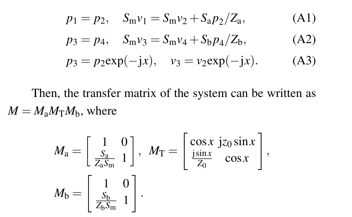
It is assumed that only plane waves propagate in the pipe,and the pressure and velocity at the left of the middle of loss part arep1andv1,at the right arep2andv2; similarly, at the left of the middle of gain part arep3andv3,at the right arep4andv4. Then, the relationships between thesepandvcan be expressed as
Z0=ρ0c0is the specific acoustics impedance of the air in main tube asρ0andc0are air mass density and acoustic velocity in tube,respectively,x=k0Lis the acoustic separation length between the gain and loss parts with the wave vectork0.
The total transfer matrix can be expressed as

Acknowledgements
Project supported by the National Key R&D Program of China (Grant No. 2017YFA0303700), the National Natural Science Foundation of China (Grant Nos. 11634006,11934009,and 12074184),the Natural Science Foundation of Jiangsu Province, China (Grant No. BK20191245), and the State Key Laboratory of Acoustics,Chinese Academy of Sciences.
猜你喜欢
中外文摘(2020年8期)2020-04-30
37°女人(2018年8期)2018-08-23
党史博览(2018年6期)2018-06-21
分忧(2018年6期)2018-06-08
南方文坛(2017年5期)2017-09-27
领导文萃(2017年1期)2017-02-09
故事会(2016年19期)2016-10-11
民间文学(2014年10期)2015-01-27
领导文萃(2014年16期)2014-08-22
中国新闻周刊(2014年11期)2014-04-21

- Chinese Physics B的其它文章
- Ergodic stationary distribution of a stochastic rumor propagation model with general incidence function
- Most probable transition paths in eutrophicated lake ecosystem under Gaussian white noise and periodic force
- Local sum uncertainty relations for angular momentum operators of bipartite permutation symmetric systems
- Quantum algorithm for neighborhood preserving embedding
- Vortex chains induced by anisotropic spin–orbit coupling and magnetic field in spin-2 Bose–Einstein condensates
- Short-wave infrared continuous-variable quantum key distribution over satellite-to-submarine channels