
Broadband low-frequency acoustic absorber based on metaporous composite
2022-06-29 09:19JiaHaoXu徐家豪XingFengZhu朱兴凤DiChaoChen陈帝超QiWei魏琦andDaJianWu吴大建
Chinese Physics B 2022年6期
关键词:徐家
Jia-Hao Xu(徐家豪) Xing-Feng Zhu(朱兴凤) Di-Chao Chen(陈帝超) Qi Wei(魏琦) and Da-Jian Wu(吴大建)
1Jiangsu Key Laboratory on Opto-Electronic Technology,School of Physics and Technology,Nanjing Normal University,Nanjing 210023,China
2Key Laboratory of Modern Acoustics,School of Physics,Nanjing University,Nanjing 210093,China
Keywords: acoustic metamaterial,low-frequency acoustic absorber,broadband,metaporous
1. Introduction
Low-frequency acoustic absorption has been a challenging problem due to the weak energy dissipation in conventional acoustic absorbers, such as porous or fibrous materials.[1–3]A thickness comparable to the working wavelength is required to achieve prominent acoustic absorption, which hinders practical applications in a low-frequency range.[4]The emergence of metamaterials provides a new approach to the high acoustic absorption at low frequency because of their locally resonant units along with large density of states inside.[5–23]Many metamaterial absorbers, such as acoustic membranes,[5–7]Helmholtz resonators,[8–12]labyrinthine metamaterials,[13–15]metasurface-based absorbers,[16–18]and split-tube resonators,[19–23]have been devised to improve the low-frequency acoustic absorption. However, most of these absorbers work in single or multiple discrete narrow bands since the high absorption occurs only at resonance.
In recent years,absorbers constructed by embedding resonators in porous materials have been proposed to widen the absorption band.[24–31]Longet al.[29]achieved perfect absorption for low-frequency audible sound waves by embedding the split ring resonator into the porous material. In Zhouet al.’s work,[30]an acoustic metaporous composite (AMC)constructed by embedding Archimedean spiral structure in the porous materials was proposed to realize the low-frequency acoustic absorption. In these absorbers, a resonant absorption is introduced into the low-frequency range based on the critical coupling mechanism in the combined systems. But their absorption bandwidths are also limited and an absorption valley will appear between the resonant absorption and the trapped mode. To further extend the bandwidth, multiple resonant units are generally required to be integrated,[32–35]which inevitably brings some restrictions on the applications in limited space.
In this work, an absorber based on an AMC is proposed for achieving the broadband low-frequency acoustic absorption. The AMC contains an embedded metamaterial resonator(two split squares with a channel structure)and a porous material layer. The finite-element simulations show that two resonant absorption peaks and one trapped mode peak can be obtained by the AMC absorber. The two resonance frequencies can be manipulated by adjusting the length of the channel. By coupling the three absorption modes, a high absorption can be achieved in a frequency range from 290 Hz to 1074 Hz.Acoustic field distribution and impedance matching theory are demonstrated to reveal the origin of the absorption peaks. Furthermore,the simulations are confirmed by the experiment results.
2. The model of the AMC
Figure 1 illustrates the two-dimensional (2D) crosssection of the AMC absorber,which is constructed by a metamaterial resonator embedded in porous material. The AMC is backed by a rigid wall that is located in thexdirection.The length of the porous material layer isL=120 mm, and its thickness isD=90 mm. The metamaterial resonator consists of two 180°-twisted split squares and a narrow channel attached to the inner split. The orientation of the splits and channel are along theydirection. The side lengths of outer and inner square area1=60 mm anda2=43 mm, respectively. The thickness of resonator walls ist= 2 mm. The widths of two splits and channel arew=3 mm. Theldenotes the length of the channel and theθis the incident angle of the sound wave as shown in Fig.1.
Based on the Johnson–Champoux–Allard (JCA)model,[2]the air-saturated porous material can be considered as a homogeneous effective fluid. The effective densityρeand bulk modulusKecan be described as

whereρ0is the air density,P0is the atmospheric pressure,ηis the air dynamic viscosity,γis the specific heat ratio,Pris the Prandtl number,ων=σφ/ρ0α∞andω′c=σ′φ/ρ0α∞are the angular Biot and adiabatic cross-over angular frequencies,respectively. Other parameters that describe the acoustic properties of porous material are porosityφ,tortuosityα∞,flow resistivityσ,thermal characteristic lengthΛ′,viscous characteristic lengthΛ,and thermal resistivityσ′=8α∞η/φΛ′.According to the simulated and measured absorptances of the porous material, the five acoustic parameters can be obtained by the backward deduction method based on genetic algorithm.[36,37]In the present study, the parameters of the used porous material areφ=0.96,α∞=1.43,σ=7000.1 N·s·m-4,Λ′=342.9 μm,andΛ=190.5 μm.
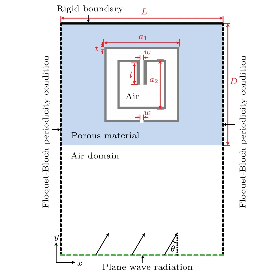
Fig.1. Geometry of modeled system,where acoustic metaporous composite(AMC)is constructed by a metamaterial resonator embedded in porous material.
Finite element method (FEM) based on COMSOL Multiphysics software is employed to perform numerical simulations,and acoustic–thermoacoustic interaction module is used.The surrounding medium is air with densityρ0=1.21 kg/m3and sound speedc0= 343 m/s. The walls are modeled as being acoustically rigid with respect to air due to the huge impedance mismatch between them. The plane wave with incident angleθ=0°is modeled as a background pressure field with an amplitude of 1.0 Pa. Figure 1 shows the geometry of the modeled system, in which the solid and dashed lines indicate the boundaries of the model domain. Floquet–Bloch periodicity conditions are applied to the left side and right side of the porous material, and the rigid boundary condition and the plane-wave radiation boundary condition are applied to the up boundary and bottom boundary.The complex reflectanceRcan be obtained from the numerical simulations and the transmittanceTequals zero due to the rigid wall backed. Then the absorptanceAcan be calculated fromA=1-R.
3. Results and discussion
Figure 2(a) shows the absorption spectrum as a function of channel lengthl, with other parameters fixed. Three absorption peaks(marked by P1,P2,and P3)can be observed in a frequency range from about 200 Hz to 1300 Hz. The P1undergoes a slight frequency shift from about 360 Hz to 305 Hz whenlincreases from 0 to 25 mm. The P2remains almost unchanged, while the P3moves markedly from about 1210 Hz to 855 Hz withlincreasing. Without the narrow channel(l=0 mm), an absorption valley appears at about 1050 Hz due to the large distance between P2and P3. Aslincreases,the enhanced coupling between P2and P3compensates for the valley between them, making the absorption continuous and efficient. Further increasingl,the P3gets too close to P2and the absorption bandwidth decreases. Meanwhile, the separation between P1and P2leads to an absorption valley at about 385 Hz. Here, the split-square with a channel structure can give rise to another absorption peak P3, and the absorption peaks P1and P3can be tuned by changing the channel length in the target frequency band. Thus, by selecting an appropriate length ofl, the three absorption peaks can be connected together to get high acoustic absorption in a broad frequency range.In Fig.2(b),we plot the absorptance forl=14 mm as a function of frequency for a better view. The absorptances are all above 0.8 in the frequency range from 290 Hz to 1074 Hz.Therefore, by embedding a single metamaterial resonator in porous material, high broadband acoustic absorption can be obtained.
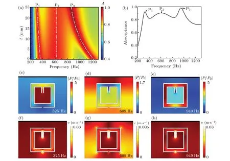
Fig.2. (a)Acoustic absorption spectrum as a function of the channel length l, with other parameters fixed. Three white dash–dot–dot lines represent the positions of three peaks P1,P2,and P3,respectively. (b)Acoustic absorptance of the AMC for l=14 mm. Black arrows mark the positions of three absorption peaks P1,P2,and P3. Distribution of((c),(d),(e))acoustic pressure|P/P0|and((f),(g),(h))velocity fields at the three peak frequencies for l=14 mm,with P being scattered acoustic pressure and P0 denoting incident acoustic pressure.
To reveal the origin of the absorption peaks,the distributions of the|P/P0| and velocity fields at the three peak frequencies forl=14 mm are displayed in Figs. 2(c)–2(e) and 2(f)–2(h),respectively.ThePis the scattered acoustic pressure andP0is the incident acoustic pressure. Figure 2(c) exhibits a maximum pressure field in the inner cavity of the AMC at 325 Hz, corresponding to a resonance mode. The large difference in acoustic pressure amplitude between inner cavity and outer split leads to a large sound velocity along the path of the splits as shown in Fig. 2(f). In consequence, the incidence sound energy is dissipated into heat due to the friction between the sound wave and walls at resonance, resulting in the absorption peak P1. Similarly,the absorption peak P3occurs at 949 Hz due to another resonance mode, which can be seen in Figs.2(e)and 2(h).Thus the principle of the metamaterial resonator is similar to that of a lossy Helmholtz resonator.For the absorption peak P1,the interior cavity acts as the tank of the Helmholtz resonator and contributes the acoustic capacitance. The function of the coiled tube between the inner and outer split shells is the long neck of the resonator,contributing the acoustic inductance and also acoustic resistance for an efficient absorption. While for another absorption peak P3, the coiled tube and the split parts of the shells paly the roles of the tank and the neck of the resonator,respectively. The added narrow channel can change the effective length of the coiled tube and then influence the positions and amplitudes of the resonance modes P1and P3.As shown in Fig.2(d),a large acoustic pressure is located between the resonator and the rigid wall at 609 Hz,which is the characteristic of a trapped mode.[24–28]The trapped mode is excited by the energy trapping between the resonator and the rigid backing,which can enhance the viscous loss and thermal loss inside the porous materials. Here,the trapped mode P2is not strong because of the large distance between resonator and the backed rigid wall,[25–27]but it can link the two resonance modes(P1and P3)and make a high absorption in a wide frequency band.The distribution of velocity field in Fig.2(g)shows that both the loss of the sound wave in porous material layer and the coupling between the resonator and porous material layer contribute to the absorption of P2.
We also conduct an analysis from the viewpoint of the impedance to explain the absorption peaks. The acoustic absorptanceAhas a relationship with the normalized acoustic impedanceZ/Z0of the AMC and it can be expressed as
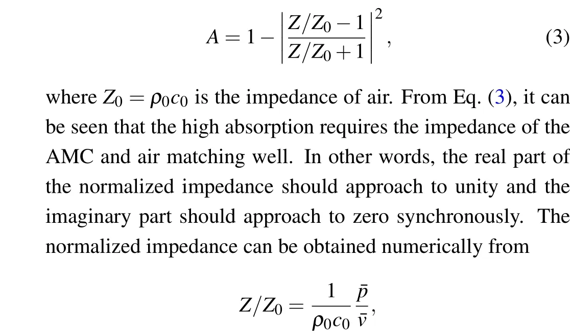
where ¯pis the average pressure and ¯vis the average velocity at the interface between air and AMC. Figures 3(a) and 3(b)exhibit the real parts and imaginary parts ofZ/Z0forl=0,14, and 24 mm, respectively. Forl=14 mm, the real and imaginary parts of the normalized impedance get close to 1 and 0 (green dot line) respectively in the range of 300 Hz–1100 Hz,which is consistent with high absorption in our calculation result. The real parts and imaginary parts of the normalized impedance get away from 1 and 0 at about 1050 Hz and 385 Hz forl=0 mm and 24 mm,respectively,where the absorption valleys appear.
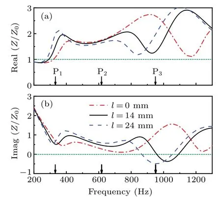
Fig. 3. (a) Real parts and (b) imaginary parts of normalized acoustic impedance for l =0, 14, 24 mm, with arrows indicating positions of three absorption peaks when l=14 mm.
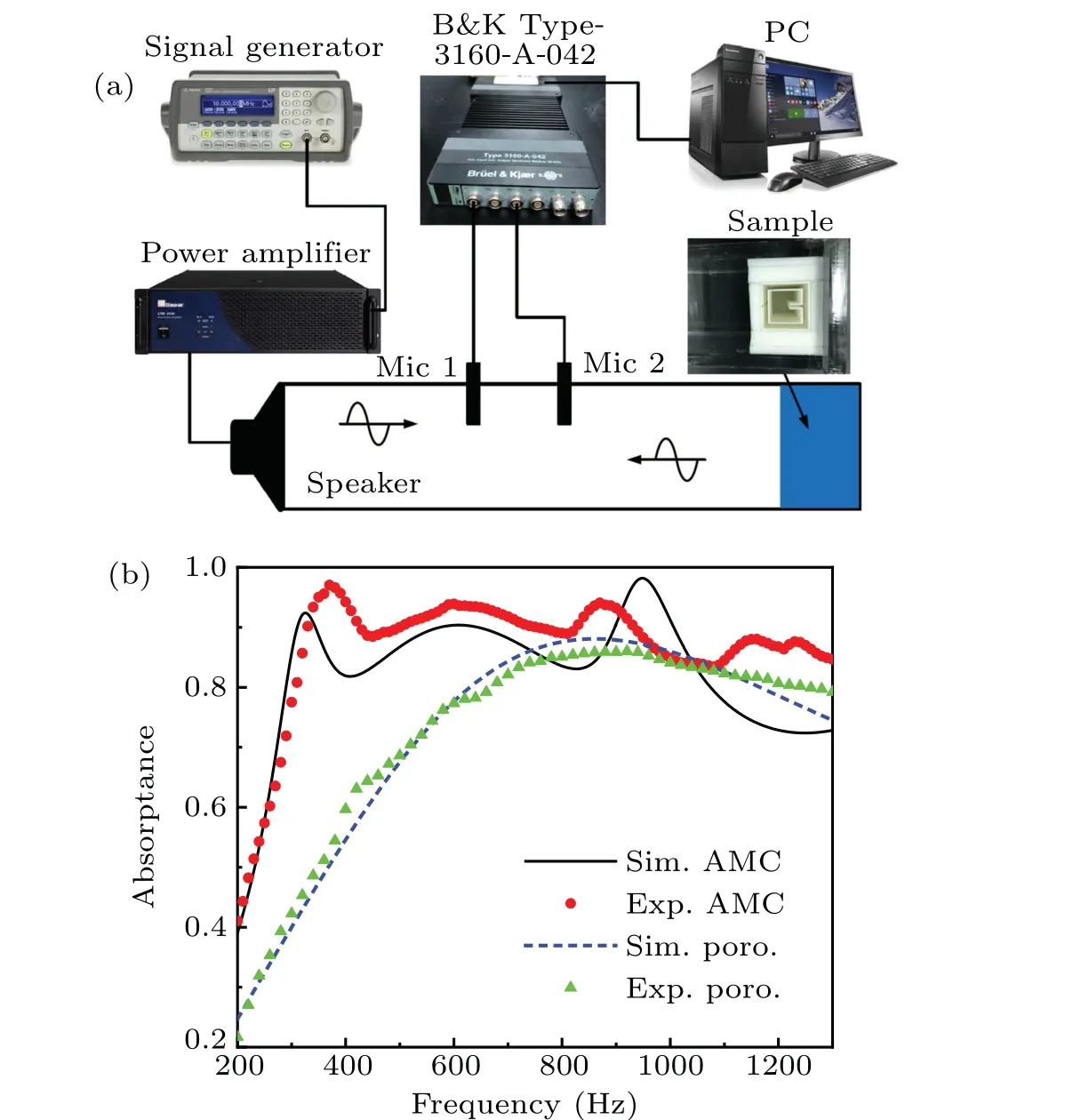
Fig. 4. (a) Schematic diagram of experimental setup, with resonator used in the work being fabricated by standard 3D printing technology and the porous material being a kind of polyurethane sponge. (b)Simulated (Sim., black solid line) and measured (Exp. red dots) absorptances of AMC compared with simulated (blue dashed line) and measured(green triangles)absorptances of the porous material without the embedded resonator.
To verify our simulation results,we measure the absorption of the AMC and the absorption of the porous material without the embedded resonator in an impedance tube by using the two-microphone method.[38]Figure 4(a) shows the schematic of the experiment setup. The resonator that we are using is fabricated by standard 3D printing technology. The porous material is the polyurethane sponge, which is commonly used for acoustic testing and sound applications. The side length of the square tube is 120 mm, corresponding to a plane wave cut-off frequency at 1429 Hz. A loudspeaker and the AMC are placed at two ends of the impedance tube to emit and absorb plane waves, respectively. The acoustic signals are received by two microphones (1/4 in., B&K Type-4938-A-011) and then analyzed by a multi-analyzer system (B&K Type-3160-A-042) to obtain the amplitude and phase of the sound wave.The acoustic absorptances measured in the experiment are shown with red dots in Fig.4(b),and the black solid line represents the simulated results. The measured(green triangles)and simulated(blue dashed line))absorptances for the porous material without the embedded resonator are also plotted in Fig. 4(b) for comparison. It is observed that the absorption of the polyurethane sponge can be described well by using the acoustic parameters of porous material in the JCA model and the porous layer has a weak absorption in the low frequency region. Three absorption peaks are observed in the presetting frequency range from about 300 Hz to 1100 Hz,which are generally consistent with the simulation results.The higher measured absorption than the simulated ones can be attributed to additional losses in the experimental setup,such as the energy leakage between different pieces forming the apparatus,the material losses,or the visco-thermal losses in the tube. The deviation of the absorption peaks P1and P3can be ascribed to the imperfect metamaterial resonator sample fabrication.

Fig.5. (a)Absorptances of AMC at different incident angles. (b)Absorptances of AMC(black solid line)compared with porous material without the embedded resonator(red dashed line)at random incident angle.
We finally study the effect of the incident angleθon the absorption of AMC. The absorptances forθ=0°, 30°, and 60°are plotted in Fig. 5(a). The absorption peaks are robust against the variation of the incident angle due to the subwavelength spatial dimension of the AMC.The frequencies of two resonance peaks (P1and P3) are almost unvaried while the frequency of trapped peak (P2) increases withθincreasing,which is in accord with the results reported previously.[30,31]The whole absorption increases with the incident angleθincreasing, because the increase of incidence angle is similar to the increase of the thickness of the porous material in the direction of sound wave propagation. Thus,the broadband absorption of the AMC can be maintained under the oblique incidence. In reality,a complicated sound field includes a number of waves with various directions rather than a single plane wave. To show the acoustic absorption of such a sound field,the random incidence absorptanceαrandof the AMC is illustrated by black solid line in Fig.5(b). Theαrandis calculated from[39]

whereA(θ) is the simulated absorptance atθ. In Fig. 5(b),theαrandfor the porous material without embedded resonator is also plotted with a red dashed curve for comparison. It can be seen that the AMC enhances the acoustic absorption especially at low frequency. These results demonstrate that the proposed AMC absorber still keeps broadband high-efficient absorption in the case of random incident acoustic waves.
4. Conclusions
We proposed an AMC absorber composed of a porous layer with a single embedded metamaterial resonator. High absorptions occur at resonant and trapped modes for the AMC absorber. The resonance frequency can be tuned by adjusting the length of the channel of the AMC, while the trapped mode frequency remains almost unchanged. The broadband absorption is achieved when the resonant modes and trapped mode are close enough to excite coupled modes. It is found that a high absorption(A >0.8)is obtained within a frequency range from 290 Hz to 1074 Hz, but the thickness of AMC is only 1/13 of the relevant wavelength at 290 Hz. The numerical simulations are experimentally validated. Additionally,the proposed AMC absorber still kept broadband high-efficient absorption in the case of random incident acoustic waves. The characteristics of high-efficiency,broadband,and compact absorber can possess the applications in building acoustics and noise remediation.
Acknowledgement
Project supported by the National Natural Science Foundation of China (Grant Nos. 12174197, 11874222, and 12027808).
猜你喜欢
美术界(2022年4期)2022-04-26
当代体育(2021年23期)2021-09-10
东坡赤壁诗词(2020年3期)2020-07-04
黄河·黄土·黄种人(华夏文明)(2019年10期)2019-11-01
黄河·黄土·黄种人(华夏文明)(2019年10期)2019-11-01
今日农业(2019年10期)2019-01-04
伴侣(2018年11期)2018-11-22
清风(2018年10期)2018-11-17
检察风云(2018年16期)2018-09-06

- Chinese Physics B的其它文章
- Ergodic stationary distribution of a stochastic rumor propagation model with general incidence function
- Most probable transition paths in eutrophicated lake ecosystem under Gaussian white noise and periodic force
- Local sum uncertainty relations for angular momentum operators of bipartite permutation symmetric systems
- Quantum algorithm for neighborhood preserving embedding
- Vortex chains induced by anisotropic spin–orbit coupling and magnetic field in spin-2 Bose–Einstein condensates
- Short-wave infrared continuous-variable quantum key distribution over satellite-to-submarine channels