
Scaled radar cross section measurement method for lossy targets via dynamically matching reflection coefficients in THz band
2022-06-29 08:57ShuangPang逄爽YangZeng曾旸QiYang杨琪BinDeng邓彬andHongQiangWang王宏强
Chinese Physics B 2022年6期
Shuang Pang(逄爽), Yang Zeng(曾旸), Qi Yang(杨琪), Bin Deng(邓彬), and Hong-Qiang Wang(王宏强)
College of Electronic Science and Technology,National University of Defense Technology,Changsha 410073,China
Keywords: scaled measurement method,radar cross section,lossy targets,terahertz
1. Introduction
Radar cross section(RCS)is one of the important physical quantities in studying the electromagnetic scattering characteristics of a target.[1,2]As one of the effective approaches to obtaining the RCS of a target, the scaled RCS measurement method is widely used for obtaining the RCS of the prototype, especially when full-size measurements are not practical.[3,4]For the scaled measurements on large prototypes, RCS measurement systems operating in a high frequency range are preferred due to the advantage in achieving high scaling factors. With the higher frequency than microwave, the terahertz (THz) band promises to realize high scaling factors, and the THz RCS measurement systems have attracted increasing research attentions.[5]In accordance with the approach to generating and detecting THz waves,various types of THz RCS measurement systems have been constructed,including solid-state THz systems,[6,7]THz laser-based systems,[8–10]and THz time-domain spectroscopy(THz-TDS)-based systems.[11,12]Based on different systems,the RCS is measured on the scaled model, and a large scaling factor is obtained in the THz band. Typically, the RCSs of scaled models such as aircrafts, tanks and armored vehicles have been obtained at a certain frequency in the THz spectrum.[13–16]
However, in the THz band, most of the RCS measurements are accomplished with the metallic model,without considering the dielectric material of a real target. There are still practical problems in the scaled RCS measurement for objects with dielectric coatings in the THz band. As is well known,the microscopic interaction mechanism becomes complicated between the terahertz wave and the media, which leads to a complex frequency response to the permittivity of the dielectric materials. The dispersive characteristic of the dielectric material is inconsistent with the scaling conditions provided by the electrodynamic similitude. This inconsistency is inevitable and still a main problem in the scaled RCS measurement in the THz band.
Some methods of solving the mentioned inconsistency in the scaled RCS measurement have been proposed. Shiet al.[17]and Shi[18]proposed an empirical formula based on the similarity theorem and dimensional analysis. According to the empirical formula, the scale factor of RCS for lossy targets is given,by which the RCS of a complex lossy target can be calculated in terms of scaled model testing. This formula works well for materials with similar reflection coefficients,while for reflection coefficients with obvious difference, the inversion accuracy decreases sharply. By approximating the RCS of the coated model, Liu and Zhang provided a scaled method for targets with lossy coatings,which is called the relaxation similitude law.[19]This method is used mainly for the specular scattering of simple shapes, and the RCS inversion accuracy is low for complex targets. According to the relaxation similitude law, Song and Zhang proposed the RCS prediction method for objects coated by magnetized plasma via scaled model using finite difference time domain(FDTD).[20]The effectiveness of the proposed method is proved by simple shapes such as sphere under certain conditions rather than complex target. In order to deal with the inconsistency in the scaled RCS measurement in visible and near infrared wave bands, Wu proposed the scaled method for laser radar cross section(LRCS),which requires the operating frequency to be unchanged.[21]Therefore, the material parameters can avoid changing.
Another solution to the inconsistency caused by the dispersive material is to design the material with the same parameter as the prototype.By changing the salinity and temperature of the simulated sea water,Zhaoet al. constructed the permittivity of sea water which satisfies the scale conditions.[22]According to high-frequency approximation algorithm, Yuanet al. proposed a method to design the scaled model with a plateshaped absorber in a wide frequency range based on the reflective loss(RL).[23]By optimizing the parameters of each layer,the RL of the scaled absorber is designed to be identical with the RL of the theoretical scaled absorber, which satisfies the scale conditions. Weiet al. designed the scaled absorbing material with a scale factor of 100 at THz band by using the hybrid Ni@mica particle,which provides a promising candidate to construct the scaled absorbing material.[24]Although the designation of a certain material has been achieved,the scope of application is limited. It is difficult to design the scaled material for any absorbing material. Besides,the thickness of the coating is comparable to the wavelength in THz band,which is different from microwave band. This will change the variation trend of the reflection coefficient along with incident angles.For the existing scaled RCS measurement methods, the variation trend of the reflection coefficient is ignored, which will lead to poor inversion precision in the scaled RCS measurement in the THz band. Thus, the characteristic of reflection coefficient should be considered for the RCS scale relation between objects with dispersive dielectric coating in the THz band.
Based on the high-frequency RCS prediction technique of physical optics (PO),[1,2]a scaled RCS measurement method for lossy objects is proposed via adjusting the reflection coefficient dynamically. The method can achieve the inversion for the RCS of the prototype with lossy coatings. The effectiveness of the method is validated through simulations.
The rest of this paper is organized as follows. In Section 2, the RCS of coated and PEC objects based on PO method is firstly deducted. Then, the proposed method for scaled RCS measurements on lossy objects is described in detail. In Section 3,the simulation results are presented and discussed. Conclusions are drawn in Section 4.
2. Theories and methods
In this section, the relationship between the reflection coefficient and the RCS is studied based on the theory of PO. Then, the RCS scaling method for lossy objects is proposed via dynamically adjusting the reflection coefficient corresponding to different aspect angles.
2.1. Algorithm of physical optics method

Comparing Eq. (2) with Eq. (3), the complex RCS of coated target can be regarded as the result of the modulation of the PEC target by dielectric coating material. On this basis,the method of dynamically matching reflection coefficients is proposed,which will be introduced in the next subsection.
2.2. Scaled RCS measurement method of dynamically matching reflection coefficients
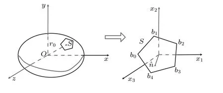
According to the electrodynamics similitude, the scaling relation for RCSs of PEC target is straightforward. While for lossy targets,the dispersive characteristic of the material is inconsistent with the scale condition. It is necessary to study the scale relation between targets with different dielectric coatings. The deduction for the complex RCS of coated target suggests that the RCS of coated target can be regarded as the modulation on PEC target by the dielectric coating. Thus,separating reflection coefficient from the complex RCS of the coated target is the key point to establishing scaling relation between targets with dispersive dielectric coatings. As is well known, the reflection coefficient is related to the incident angle. For an arbitrarily shaped object which contains a variety of facets,the angle included between normal direction and incident direction is different from the scenario of the facets at one illuminating direction.Based on the distribution of normal directions of facets, the reflection coefficient is dynamically matched under different aspect angle.
Taking the coated cylinder for example,the schematic of the proposed method is presented in Fig. 2, wherekiis the vector of wave number corresponding to the incident wave;θ1andθ2represent the angles included between the normal direction and incident direction of different facets. As shown in Fig.2,θ1andθ2change with the incident direction,which is the key to matching reflection coefficient with corresponding facets. Taking an object with two kinds of facets for example,the flow chart of the proposed method is shown in Fig.3.


This can be applied to an object withmkinds of facets. The validity of the proposed method is proved through simulation,which will be presented in next section.
3. Simulation experiments and results
In order to evaluate the effectiveness of the proposed method,simulation experiments on coated SLICY model were conducted,and the model is shown in Fig.4.
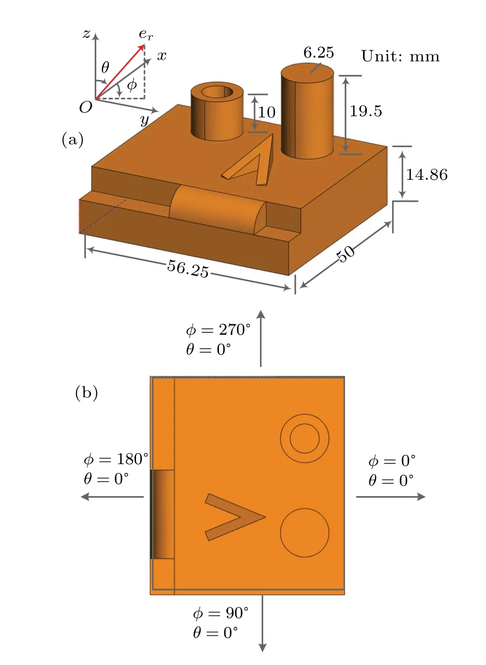
In simulation, monostatic complex RCSs of the constructed PEC and coated SLICY models were calculated respectively, by the commercial electromagnetic computing software(CST Microwave Studio)through using the shooting and bouncing ray (SBR) method. Two groups of simulations were designed on models coated with different materials in order to investigate the influence of reflection coefficients on the inversion precision of RCS. The reflection coefficients of the coatings in the first group,obtained from the prototype model and the scaled model were similar. For the second group,the reflection coefficients of the coatings were different from each other obviously. For the SLICY model, the distributions of scattering centers are different at different aspect angles.In order to study the inversion precision of RCS corresponding to different distributions of scattering centers, four azimuth angles ofφ(the angle between the incident plane and the plane ofXOZ) were chosen and RCSs corresponding toθ(the angle between the observation direction andzaxis)in a range of 0°–180°at eachφangle were calculated in each group of the simulation experiments. The geometric diagrams of different aspect angles are shown in Fig.4(b).
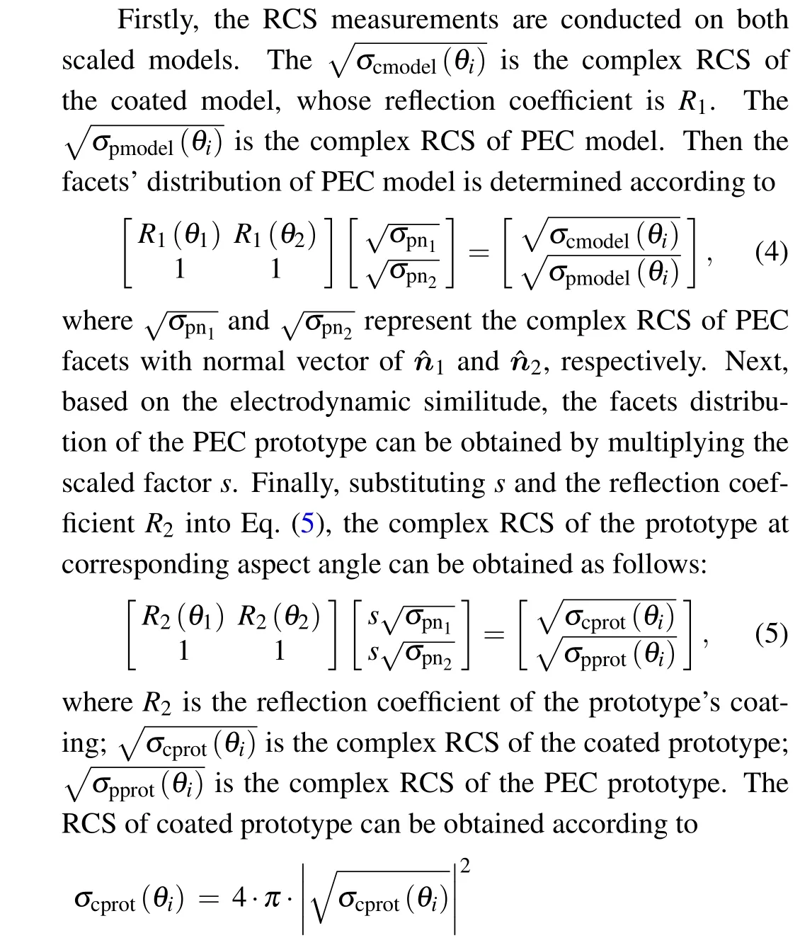
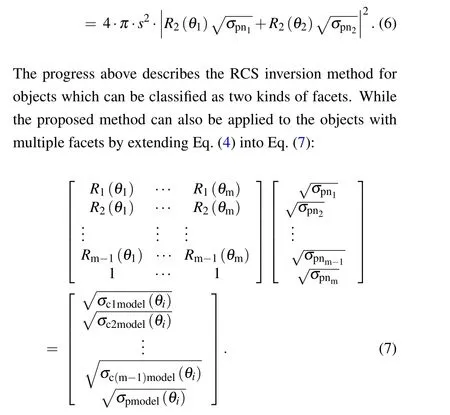
Based on the complex RCSs of the scaled PEC model and coated model via simulation calculation, the RCS of the coated prototype can be obtained as follows. Firstly, two kinds of facets with mutually perpendicular normal vectors were chosen, according to the dominant specular scattering within aspect angles. Next, the reflection coefficients were calculated based on the Fresnel’s formula corresponding to different included angles between the facets’ normal vectors and the incident direction. Then, substituting the reflection coefficients, the complex RCS of coated model and the complex RCS of PEC model into Eq.(4),the distribution of PEC facets was obtained,and the complex RCS of coated prototype at corresponding aspect angle could be calculated according to Eq.(5). Finally,the RCS of the coated prototype was given by Eq. (6). The inversed RCSs of the prototypes corresponding to different coatings are shown below respectively.
3.1. Results of first group
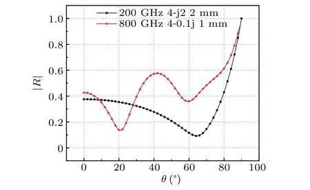
The configuration of parameters is listed in Table 1,with the geometric scale factor being 1:4. The reflection coefficients of the coatings on prototype and the scaled model are shown in Fig. 5, which are calculated based on the Fresnel’s law. The inversed RCSs of the prototypes are presented in Fig.6.
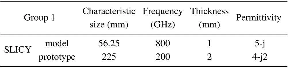
Group 1 Characteristic Frequency Thickness Permittivity size(mm) (GHz) (mm)SLICY model 56.25 800 1 5-j prototype 225 200 2 4-j2
As shown in Fig. 6, the inversed RCS of the prototype obtained in the proposed method is consistent with the calculated result, demonstrating the effectiveness of the proposed method. Besides, the inversed results are compared with results obtained from the Shiet al.’s method,which also proves the utility of the proposed method.
3.2. Results of the second group
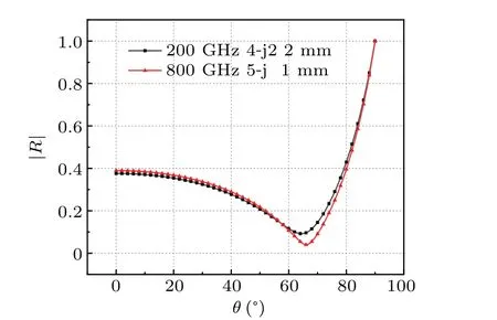
For the second group, the configuration of parameters is listed in Table 2. As shown in Fig. 7, the reflection coefficients are obviously different from each other. Corresponding inversed RCS results are shown in Fig.8.

Group 2 Characteristic Frequency Thickness Permittivity size(mm) (GHz) (mm)SLICY model 56.25 800 1 4-j0.1 prototype 225 200 2 4-j2
As shown by the results, the inversed RCS of the prototype obtained in the proposed method is consistent with the calculated results in most aspect angles. While the inversed results given by the Shiet al.’s method present obvious error at certain aspect angles. The main difference between the proposed method and the Shiet al.’s method lies in the approach to approximating the reflection coefficient. In the Shiet al.’s method, the reflection coefficients of different aspect angles are approximated as then-th power of the specular reflection coefficient.This approximation works well for reflection coefficients with similar dependence on the aspect angle.However,in the THz band, the wavelength is in the same magnitude as the thickness of the dielectric coating,which leads the reflection coefficient to fluctuate obviously. For the method proposed in this paper, the reflection coefficients of different aspect angles are determined by the distribution of facets,which can improve the precision of the inversed RCS as shown in Fig. 8. Comparison between the proposed method and the method of Shi suggests that it is necessary to match the reflection coefficient based on the distribution of facets, especially for materials with obvious fluctuated reflection coefficients in the THz band. It is worth noting that the SLICY model is composed of standard geometric shapes possessing specular scattering centers,which is suitable for the proposed inversion method of RCS based on PO approximation. Considering the complicated scattering caused by the interactions between the structure and the electromagnetic waves,the proposed method needs further improving the adaptivity to objects with complex structures.

4. Conclusions and perspectives
In this paper, a scaled RCS measurement method is proposed based on the high-frequency estimation method of PO.Through dynamically matching the reflection coefficients according to the distribution of the facets, this method can achieve the inversion of RCS for the lossy prototype with high precision. By comparing with Shiet al.’s method,the validity and advantage of the proposed method is demonstrated,especially for lossy objects whose reflection coefficients are obviously different in the THz band. This method will extend the application of scaled RCS measurement on lossy objects in the THz band,which will further promote the study of the object’s scattering characteristic in the THz band.
Acknowledgements
Project supported by the National Natural Science Foundation of China(Grant Nos.61871386,61971427,62035014,and 61921001) and the Natural Science Fund for Distinguished Young Scholars of Hunan Province, China (Grant No.2019JJ20022).

- Chinese Physics B的其它文章
- Ergodic stationary distribution of a stochastic rumor propagation model with general incidence function
- Most probable transition paths in eutrophicated lake ecosystem under Gaussian white noise and periodic force
- Local sum uncertainty relations for angular momentum operators of bipartite permutation symmetric systems
- Quantum algorithm for neighborhood preserving embedding
- Vortex chains induced by anisotropic spin–orbit coupling and magnetic field in spin-2 Bose–Einstein condensates
- Short-wave infrared continuous-variable quantum key distribution over satellite-to-submarine channels