
Three-Dimensional Model Reconstruction of Nonwovens from Multi-Focus Images
2022-08-08 05:47DONGGaige董改革WANGRongwu王荣武LIChengzu李成族YOUXiangyin尤祥银
DONG Gaige(董改革), WANG Rongwu(王荣武)*, LI Chengzu(李成族), YOU Xiangyin(尤祥银)
1 College of Textiles, Donghua University, Shanghai 201620, China 2 Jiangsu Liyang New Material Co., Ltd., Nantong 226004, China
Abstract: The three-dimensional(3D)model is of great significance to analyze the performance of nonwovens. However, the existing modelling methods could not reconstruct the 3D structure of nonwovens at low cost. A new method based on deep learning was proposed to reconstruct 3D models of nonwovens from multi-focus images. A convolutional neural network was trained to extract clear fibers from sequence images. Image processing algorithms were used to obtain the radius, the central axis, and depth information of fibers from the extraction results. Based on this information, 3D models were built in 3D space. Furthermore, self-developed algorithms optimized the central axis and depth of fibers, which made fibers more realistic and continuous. The method with lower cost could reconstruct 3D models of nonwovens conveniently.
Key words: three-dimensional(3D)model reconstruction; deep learning; microscopy; nonwoven; image processing
Introduction
The three-dimensional(3D)model of nonwovens could reflect the stacking structure of fibers.With the help of simulation software, it is an effective method to predict the material’s performance through the 3D structure model of the material.In this way, researchers have predicted the permeability[1], the filtration efficiency[2], and the flow resistivity[3]of nonwovens.Therefore, it is valuable to construct 3D structural models of nonwovens.Researchers have proposed several methods to reconstruct the 3D structural model of materials.Confocal microscopes and computed tomography(CT)technology are commonly used to reconstruct 3D models.Recent researches have proved that the 3D virtual model constructed based on the fiber radius, the orientation, and other parameters could also be used to analyze the sound absorption performance[4]and filtering performance of nonwovens[5].Sambaeretal.[2]constructed single-layer nanofiber models based on the scanning electron microscope(SEM)images, and then stacked four single-layer models to form a complete 3D model.However, these methods could not reconstruct the 3D model of the material quickly and less-costly.Therefore, it is valuable to design a low-cost method to establish 3D structural models of nonwovens.
An optical microscope is a low-cost device for acquiring images of nonwovens compared with SEM and CT technology.When the sample moves vertically to the focus plane of the microscopy, a set of multi-focus images will be acquired continuously.Since the microscope’s depth of focus is smaller than the thickness of the material, it is impossible for all fibers to be clearly imaged in one microscope image.Researchers have found methods to fuse multi-focus images and obtain a fused image with higher clarity.Plenty of researches have been focusing on the measurement of nonwovens structures from multi-focus images[6-9], which indicates that multi-focus images are significant for analyzing the structure of nonwovens.
Deep learning has become a hot research area in artificial intelligence, because of its strong learning ability.Deep learning technology is widely used in various fields, such as image processing, medicine, and computer vision[10].Researches have shown that deep learning technology is an important method for multi-focus image fusion[11]and image segmentation[12].In the field of microscopy, Luoetal.[13]demonstrated a deep learning-based method for single-shot autofocusing, which could autofocus a single-shot microscopy image acquired at an arbitrary out-of-focus plane rapidly and blindly.Rivensonetal.[14]utilized the deep learning method to enhance optical microscopy images by improving their resolution.Houetal.[15]designed a convolutional neural network to extract in-focus objects from multi-focus images of nonwovens.Because deep learning performs well in image processing, it is also feasible to extract fibers from images with the help of deep learning.
This paper proposed a low-cost and convenient method to construct 3D models from multi-focus images of nonwovens.The method includes deep learning and image processing algorithms.Firstly, a self-developed program controls the image acquisition devices and captures multi-focus images of nonwovens.Secondly, a deep learning neural network is trained to extract in-focus fibers from multi-focus images.Thirdly, image processing algorithms calculate the depth, the radius, the central axis of fibers from the results extracted by the network.The 3D structural model is constructed based on the information.Finally, the center axis and depths of fibers are modified to ensure the continuity of fibrous structures, leading to a better 3D model.Our experiments have proved that it is possible to build a 3D model of nonwovens based on multi-focus images.
1 System Set-up
The image acquisition system consists of a camera(JAI BM-141GE, Japan), an optical microscope(BEION M318, China)with a 10X object lens(Labomed, USA), as shown in Fig.1.In order to ensure the accuracy of the image acquisition process, we developed a program to adjust the position of the platform precisely, display images, and control the camera to capture images.During the image acquisition process, the platform moves upward with a fixed step distance.When the platform moves by one step, a digital image is captured accordingly.As the platform moves step by step, fibers in the captured image gradually change from blurry to partially clear, and then gradually change from partially clear to blurry.When all fibers become blurry from clear, a batch of multi-focus images is obtained, as shown in Fig.2.Because images are captured at different depths, they have different clarity, as shown in Fig.3.
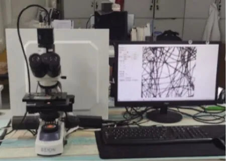
Fig.1 Image acquisition system
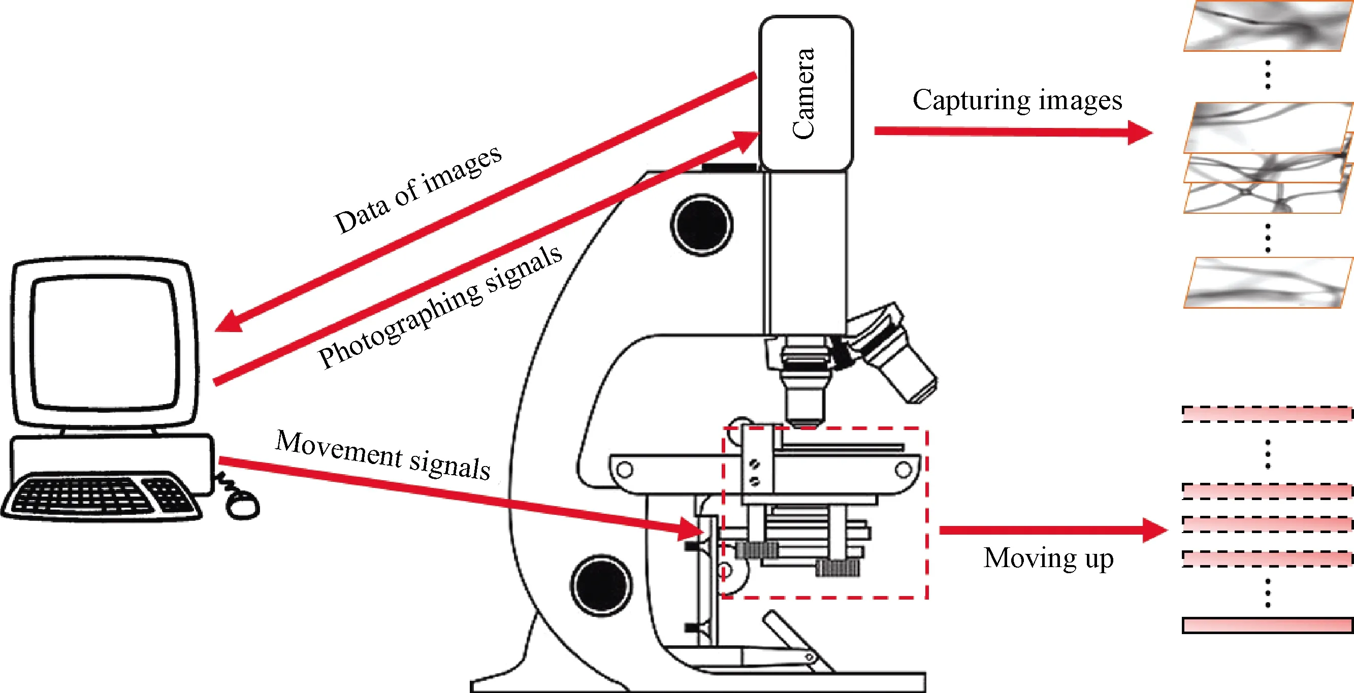
Fig.2 Image acquisition process
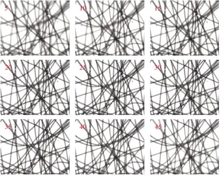
Fig.3 Nine samples of multi-focus image sequence(red numbers refer to serial numbers of images in sequence)
2 In-Focus Fibers Extraction
Each image in a multi-focus image sequence is taken at different depths.In a multi-focus image sequence, one fiber is clearly imaged in several consecutive images, but in these images, the clarity of the fiber is various.It is feasible to calculate the actual depth of the fiber according to its sharpness in each image of the sequence.Extracting in-focus fibers from multi-focus images is the first step.The gradient can indicate the sharpness of the image at a certain point, but it is more sensitive in the edge area of the fiber.Threshold, a common image segmentation method, could not distinguish whether the fiber in the image is clear or not.It is complicated to extract evident fibers by using image processing algorithms.Deep learning is more suitable for this task.Ronnebergeretal.[16]proposed a deep learning pioneering model called U-Net.U-Net could take full advantage of feature maps in the contracting path to increase pixel localization accuracy and achieve good image segmentation performance.Thus, we choose U-Net to extract clear fibers from multi-focus images.The architecture and details of the network are shown in Fig.4.Except that the activation function of convolutional layer 19 is softmax, the activation functions of all other convolutional layers and deconvolutional layers are ReLU.
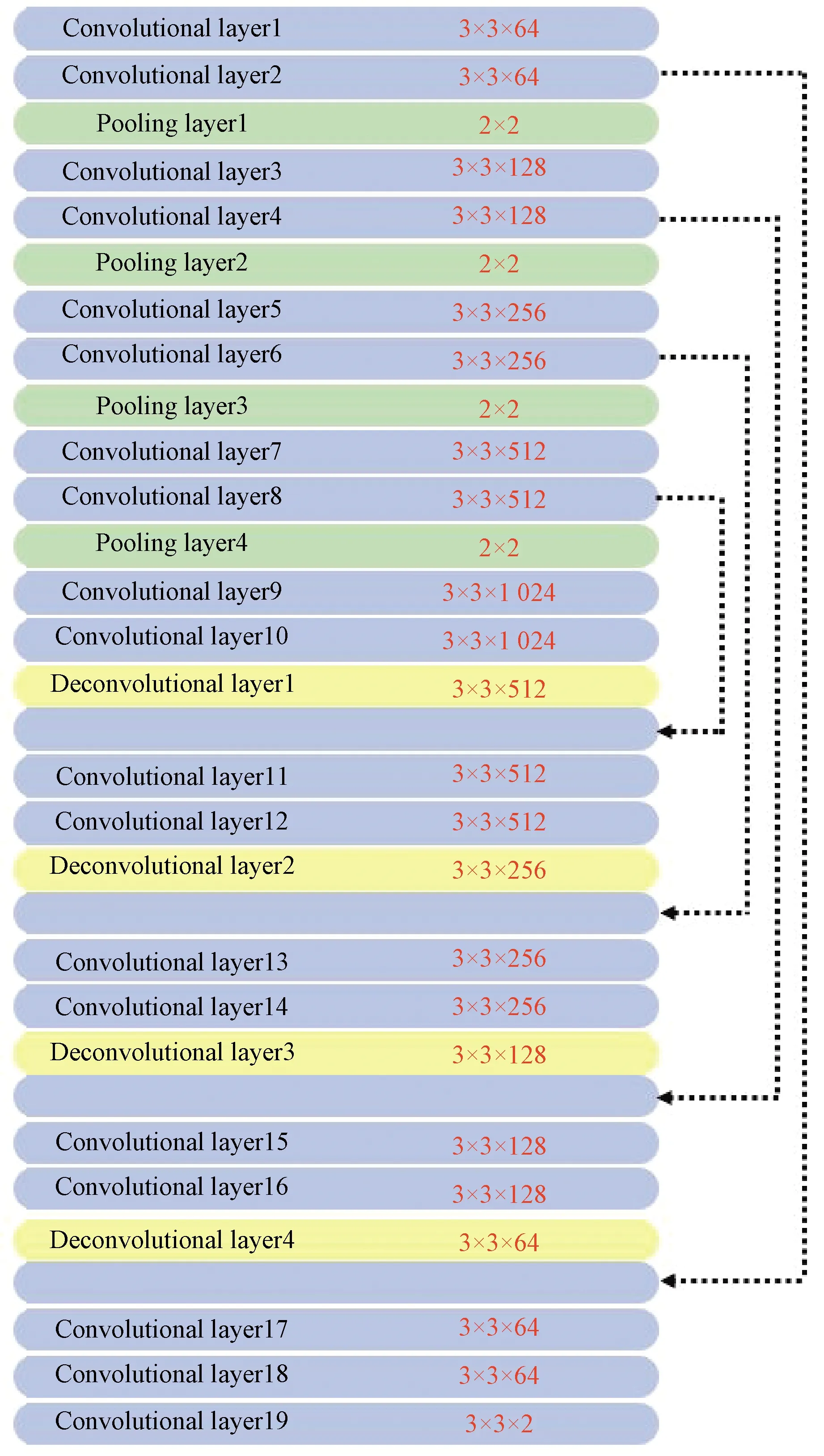
Fig.4 Network architecture(dashed arrows refer to copy and concatenate operations, and red numbers represent kernel size of the layer)
No suitable dataset is available for extracting in-focus fibers in a microscopic image, so a dataset specifically for the extracting process is created.Multi-focus images are cropped into small images with a size of 320×320 pixels.Human observer labeled in-focus fibers in images manually to obtain ground truth, as shown in Fig.5.The dataset contains 1 200 small images: 1 150 images are used as the training set, and 50 images for validation.During training, loss is set as categorical cross-entropy.The loss value and the accuracy of the network could not decrease obviously after ten epochs training.The loss of the validation is stable around 0.1, as shown in Fig.6.The clear fibers extracted from the network and those manually marked have high consistency, as shown in Fig.7, which means that the network can distinguish between in-focus fibers and background.
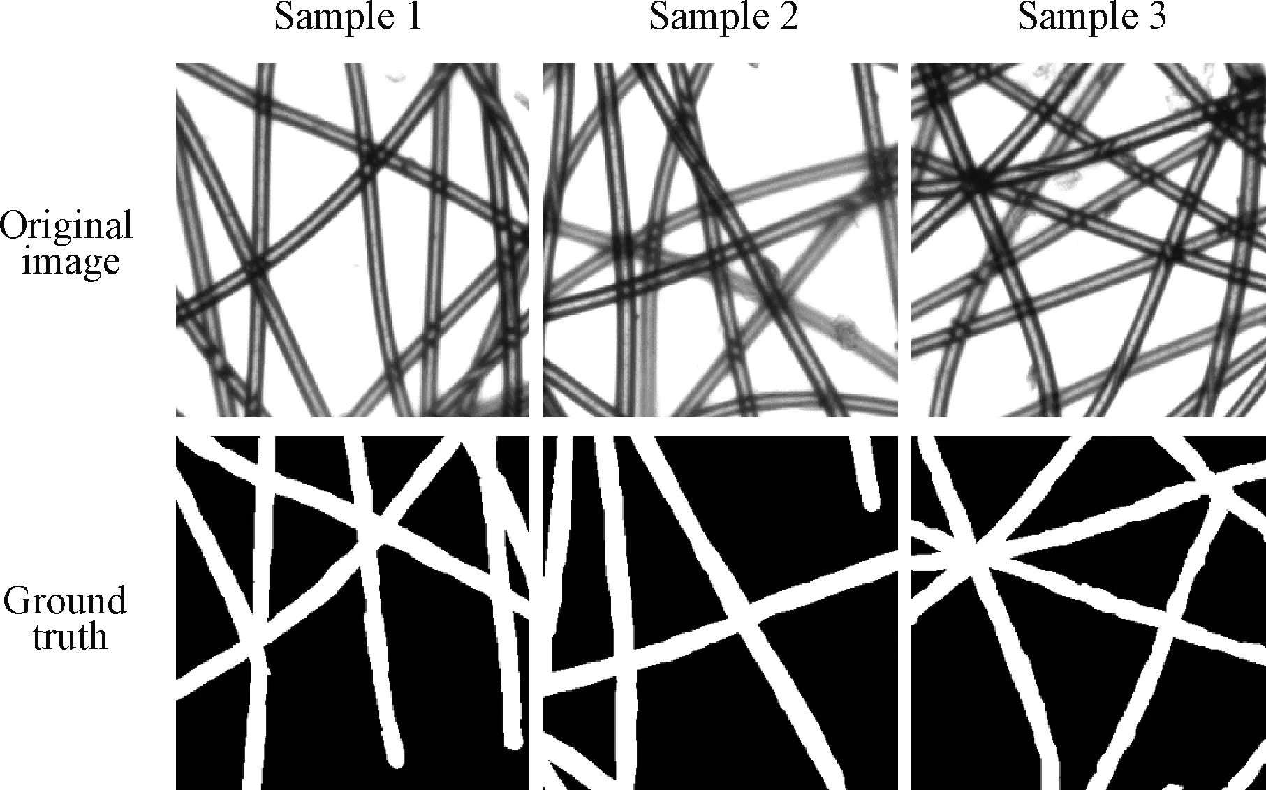
Fig.5 Sample images of dataset
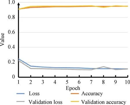
Fig.6 Learning curves of model training

Fig.7 Comparison of ground truth and result of network
3 3D Model Reconstruction
In order to simplify the modelling process, a long fiber is regarded as many continuous segments.In a multi-focus image sequence, one fiber segment is only sharply focused in several consecutive images.The depth of the segment can be calculated based on the relative depth of these images.Image processing algorithms extract the central axis of fibers and calculate the radius of fibers from digital images.Each point on the fiber axis is regarded as a fiber segment.We build models of all segments in 3D space, and these models form the model of nonwovens.In order to construct models, the image acquisition system captures several multi-focus image sequences of nonwovens, each sequence contains 100 images, and the trained artificial neural network extracts clear fibers from these images.The subsequent steps are as follows.
3.1 Image preprocessing
The artificial neural network extracts in-focus fibers from cropped images, shown in Figs.8(a)and 8(b).Nevertheless, the extraction results contain noises, so preprocessing is essential for subsequent steps.Preprocessing consists of two steps: morphological processing, including the open operation and the close operation, smooths the edge of these images; regions with an area less than 200 pixels are regarded as noise and deleted from images, as shown in Fig.8(c).Preprocessing transforms the extraction results into segmented images, and these segmented images are the basis of the reconstruction process.
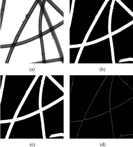
Fig.8 Example of image processing:(a)original image;(b)fiber extracting result;(c)preprocessing result;(d)skeleton image
3.2 Central axis extraction
Fibers in nonwovens are randomly distributed, so it is necessary to determine the arrangement direction and the position of each fiber before reconstructing the model.The central axis of the fiber can achieve this goal well.Image skeletonization means extracting the central pixels of the area, and its target is gaining lines with single-pixel width.Because the skeletons of fibers in the digital images are similar to their central axes, we regard the skeletons as axes.In this paper, we adopt the iterative skeletonization algorithm in Ref.[17]to extract skeletons, as shown in Fig.8(d).In iterations, points that satisfy the four equations will be deleted, and skeletonization is finished when there are no points to delete.
The four equations are
2≤BP1≤6,
(1)
AP1=1,
(2)
P2×P4×P6=0,
(3)
P4×P6×P8=0,
(4)
whereP2,P3, …,P9are values of eight neighboring points ofP1, starting from the neighboring up point and numbering in counterclockwise order;BP1means the number of nonzero neighbors ofP1;AP1means the number of 01 patterns in the ordered setP2,P3, …,P9.Equations(3)and(4)have another form in Eqs.(5)and(6).In iterations, points that satisfy Eqs.(1),(2),(5), and(6)will be deleted.
P2×P4×P8=0,
(5)
P2×P6×P8=0.
(6)
3.3 Depth calculation
Depth is the key information to transform two-dimensional(2D)multi-focus images into a 3D model.Not only fiber segments on the focus plane but also segments within a certain range above and below the focus plane can be seen clearly in the multi-focus images.In other words, in the range, the segment is visual.Thus, each skeleton point in the skeletons could be recognized by the network in several continuous images.For a skeleton point, the mean value of the highest visual depth(HVD)and the lowest visual depth(LVD)is regarded as the depth of the point, as shown in Fig.9.In Fig.9, each dash line indicates one image captured at the depth, the blue region means the side view of a fiber, the red point means the skeleton point, the green lines represent HVD and LVD of the red point, and the average of HVD and LVD is regarded as the actual depth of the skeleton point.
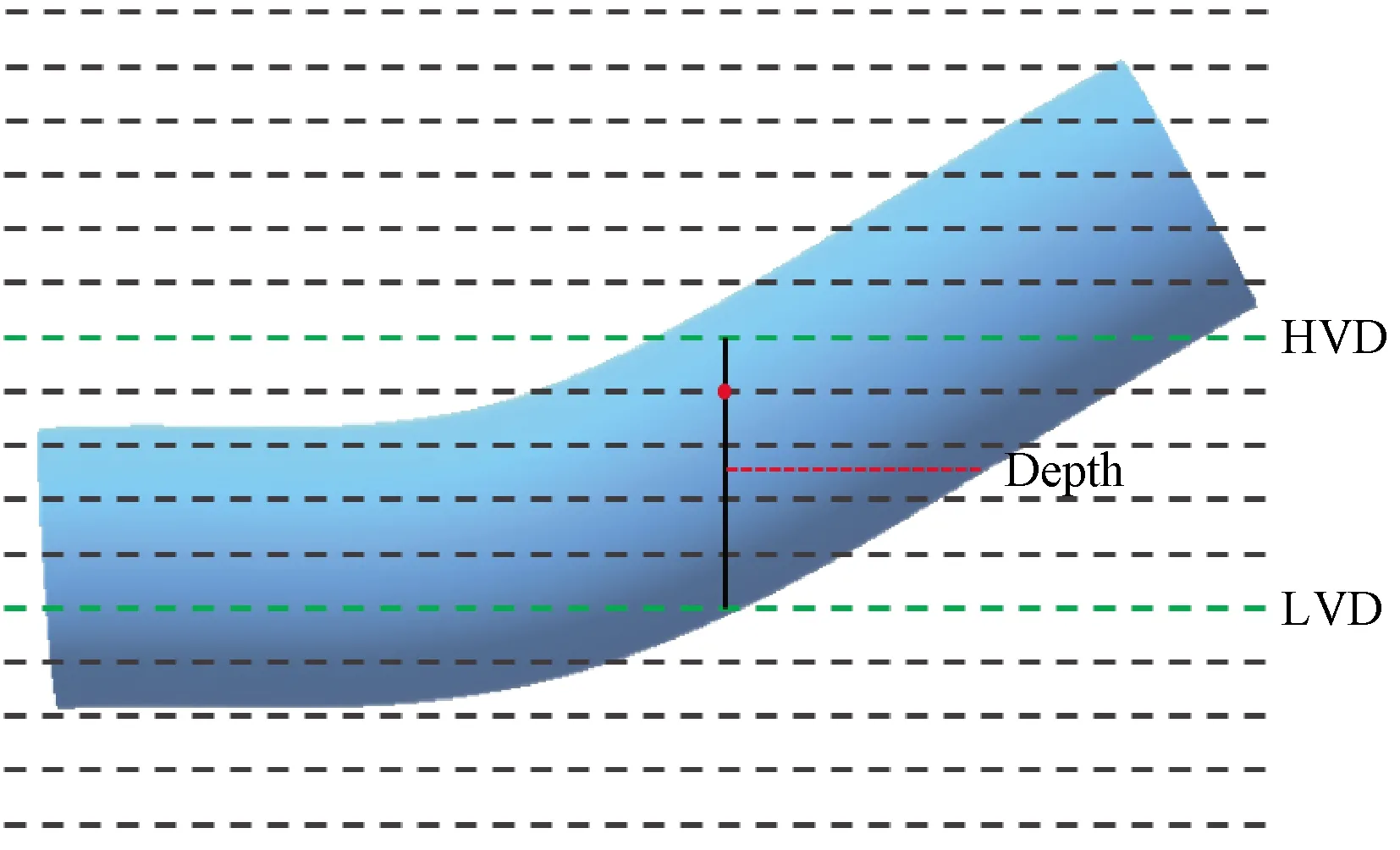
Fig.9 Schematic diagram of depth calculation
3.4 Radius calculation
The radius of a fiber is not fixed, and the radius of different parts of the same fiber may be various.In order to build a realistic 3D model, the adaptive algorithm is suitable for calculating the radius of every skeleton point.The radius of the fiber at a certain skeleton point is considered to be the nearest distance from the point to the boundary of the fiber.For the same fiber, the radius measured in different images is various.For instance, the radius measured in HVD and LVD is smaller than other images.Thus, the first step of radius calculation is stacking segmented images between HVD and LVD.Stacking process overlaps white pixels in these images, and a fused image is obtained, in which the width of the fiber is equal to its real diameter.It is uncomplicated to measure the radius of all skeleton points in the fused image.As shown in Fig.10, gray points represent fibers in the overlapped image, and white points represent the skeleton points of fibers.
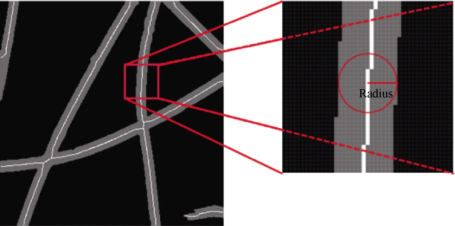
Fig.10 Radius calculation diagram
3.5 3D fiber reconstruction
Since the skeleton of fibers, the radius and depth of skeleton points have been obtained, it is feasible to reconstruct the nonwovens’ 3D model based on this information.In 3D space, each point in the skeleton is regarded as a segment of the fiber, and the model of the segment is set to be a sphere.Suppose that the coordinate of a skeleton point is(xc,yc), the radius isr, and the depth isd.InX-Y-Zcoordinates, the set of all points satisfying Eq.(7)is a small sphere.With the depth and the radius, each skeleton point is modelled as a small sphere in 3D space.These spheres form a 3D model of the fiber.The 3D model of nonwovens can be obtained by combining the 3D models of all fibers, shown in Fig.11.The 3D model can clearly show the distribution, orientation, and depth of fibers.
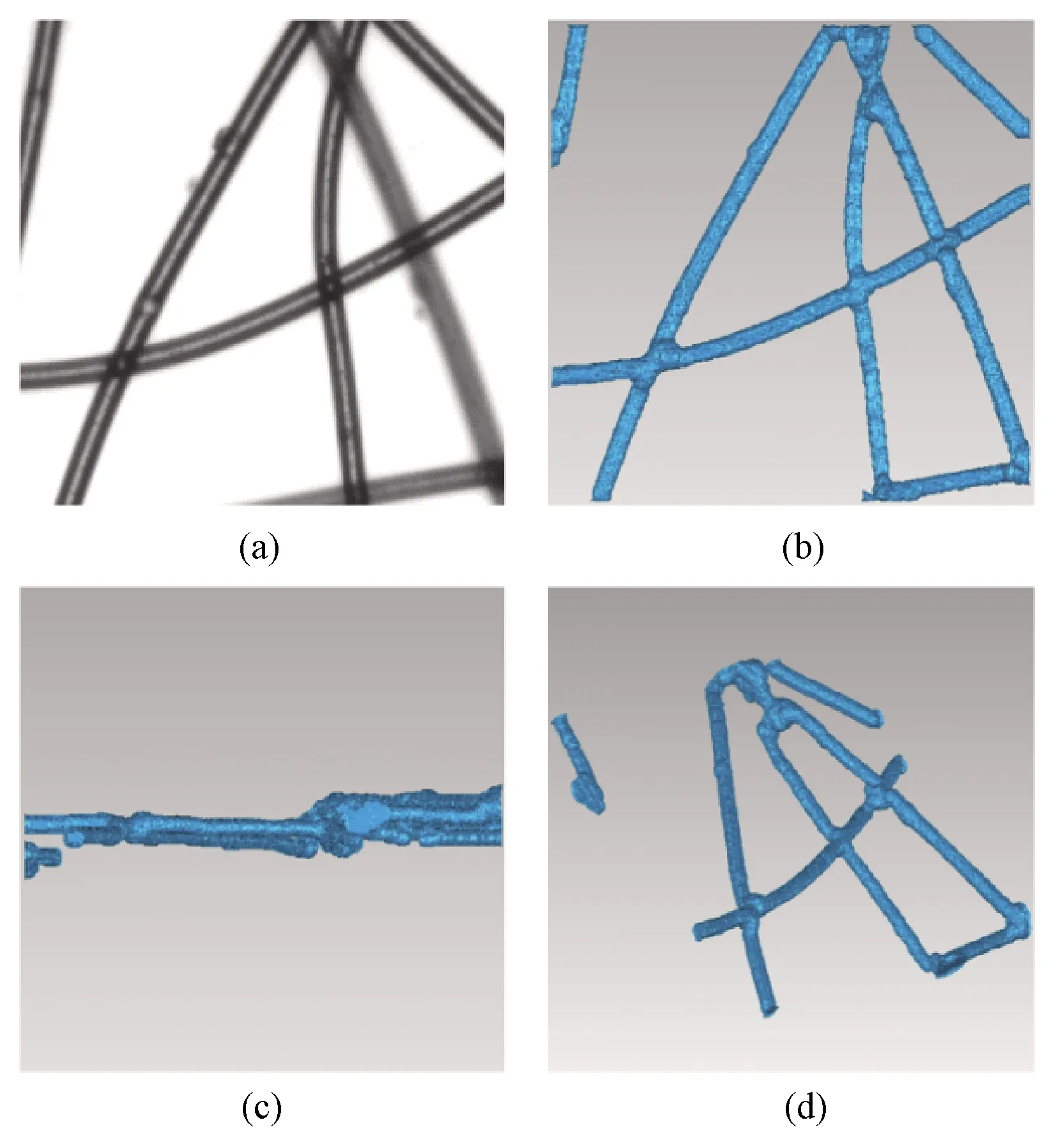
Fig.11 Original images and 3D models of nonwovens:(a)original image;(b)top view;(c)side view;(d)random view
(x-xc)2+(y-yc)2+(z-d)2≤r2.
(7)
4 Modification of 3D Models
If the depths of two fibers are similar, the visual ranges of them are connected at the intersection of them.In the depth calculation process, they share the same HVD and LVD.Hence, the calculated depths of the two fibers at the intersection are the same but not accurate, so fibers near the intersections may distort.In order to solve this defect, we developed algorithms to optimize models.Since the distortions always occur near the intersection of fibers, intersection points are firstly identified, and then skeleton points near them are deleted.Complete fiber skeletons are broken into skeleton fragments, and generate four endpoints.The inclination angles of these fragments at the endpoints are calculated.We draw straight lines to connect endpoints with similar inclination angles and keep fibers straight near intersections.
4.1 Deleting skeleton points
The first step of modification is to identify the intersections of fibers.It is easy to obtain a fusion image from the top view of the 3D model.The algorithm in Ref.[17]can extract the skeleton of all fibers from the fusion image, as shown in Fig.12.A skeleton point will be regarded as an intersection point if Eq.(8)or(9)is satisfied.If the distance between a skeleton point and an intersection point is less than 10 pixels, the skeleton point will be deleted, which breaks the complete skeleton lines into skeleton fragments, as shown in Fig.13.
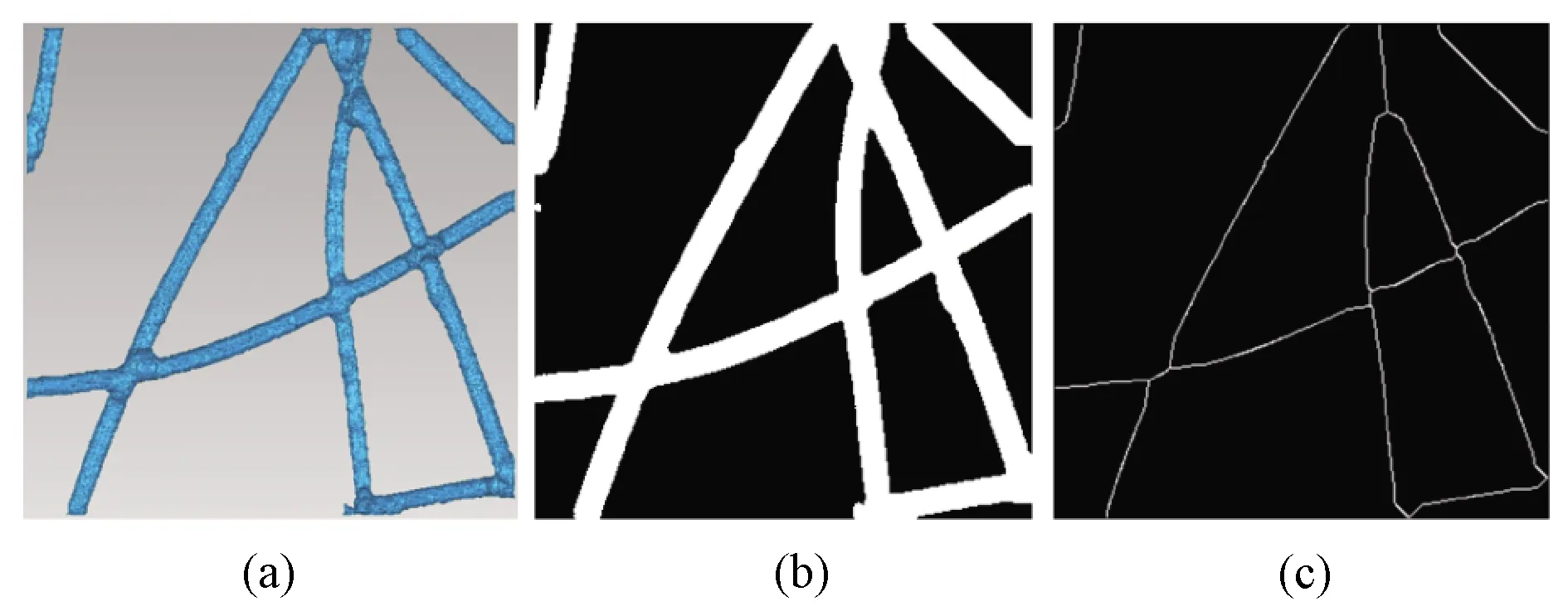
Fig.12 Complete skeletons of all fibers:(a)top view of the model;(b)fused image;(c)skeleton of fused image
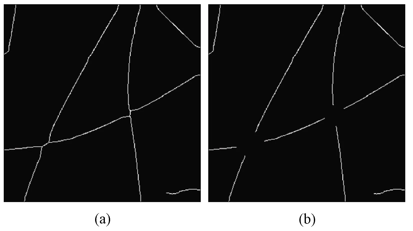
Fig.13 Broken skeletons:(a)complete skeleton;(b)skeleton fragment
2≤BP1,
(8)
AP1≥3.
(9)
4.2 Angle calculation

Fig.14 Skeleton points marking(red point represents an endpoint, and green points represent marked skeletons)
(10)
4.3 Connecting fragments
We assume that when two fibers cross each other, their skeletons are extremely straight near the intersection.So the inclination angles of the fragments from the same fiber are very close.After skeleton points deleting, the skeletons of the two intersecting fibers have four end points near the intersection.If the difference between the angles of the two endpoints is less than 15°, we consider that they belong to the same fiber, and connect them with a straight line, as shown in Fig.15.The points on the straight line are regarded as skeleton points.With the depth and the radius, these points can be reconstructed into fiber fragments in 3D space, which can eliminate the distortion of fibers and obtain more realistic models.The method to calculate the differences between two anglesθAandθBis expressed by Eq.(11).For pointPon the new skeleton connecting endpointsAandB, its depth is expressed by Eq.(12).The radius of points on the new skeleton are obtained by the method which is introduced in section 3.4.If none connecting line is drawn, the points near the intersection will remain as in the model before modification.

Fig.15 Extension lines at the end points of skeletons(gray lines represent connecting lines, and white lines represent fragments of skeletons)
(11)
whereDABmeans the difference between anglesθAandθB.
(12)
whereDPmeans the depth ofP,DAandDBpresent the depth ofAandBcalculated in the method which is introduced in section 3.3,LAPmeans the distance betweenAandP, andLABmeans the distance betweenAandB.
4.4 Modified model reconstruction
The algorithms mentioned above have deleted the skeleton points near the intersection of fibers, and new skeleton segments are established based on inclination angles.The depth and the radius of these skeletons are also available.Therefore, better 3D models of nonwovens can be reconstructed based on this information.As shown in Figs.16 and 17, fibers in the modified model will not distort near its intersections.This model can reflect the distribution of fibers more realistically.
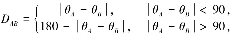
In order to verify the robustness of this method, we construct three 3D models of nonwovens, as shown in Fig.18.The first column of Fig.18 represents one image of the nonwovens’ multi-focus images.The second and the third columns respectively show the top view and random view of the 3D model corresponding to the first column.Comparing the images in the first column with the images in the other two columns, it is obvious that the 3D models we reconstructed are in good agreement with the images of nonwovens.The stacking and crossing of the fibers in the model are also consistent with those in materials.
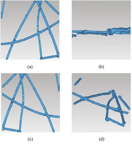
Fig.16 Modified 3D model:(a)top view;(b)side view;(c)bottom view;(d)random view
Fig.17 Comparison of modified model and original model from the same perspective:(a)original model;(b)modified model
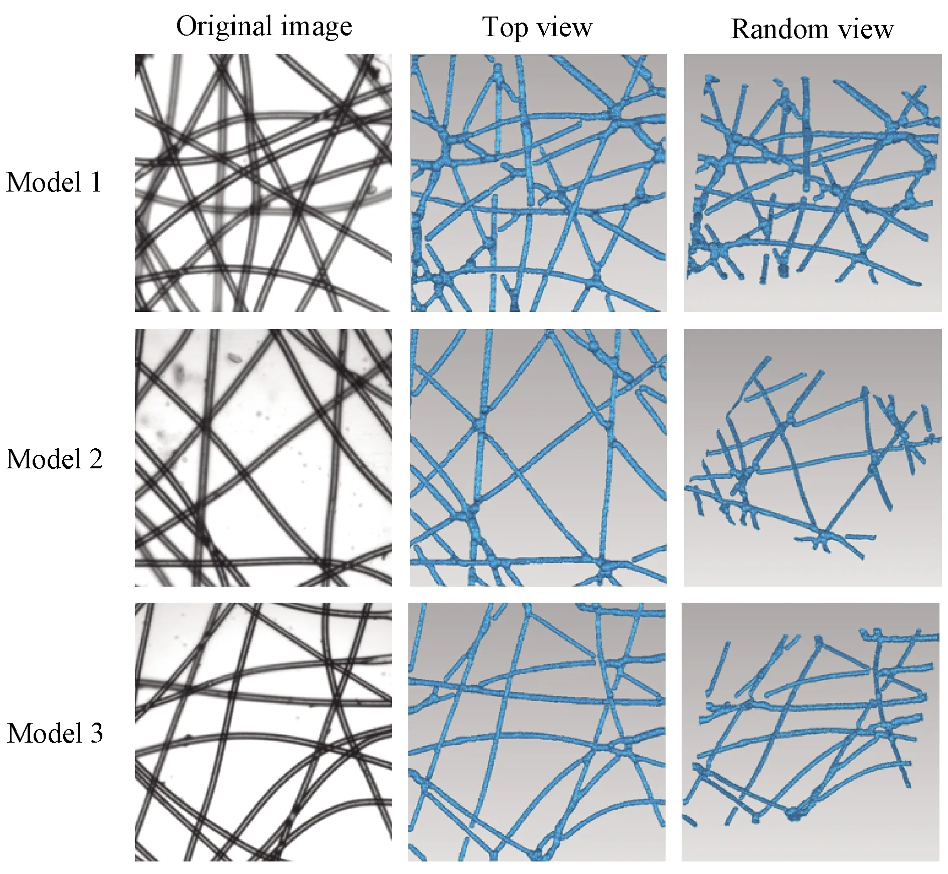
Fig.18 3D reconstruction models
The method we proposed in this paper successfully reconstructs 3D models of nonwovens based on multi-focus images.Only an optical microscope and a camera are needed in the reconstruction process, which means that the cost of our method is lower than those based on CT.The 3D models can be imported into the finite element analysis software to simulate the performance of nonwovens[18].
5 Conclusions
In this paper, we developed a method to capture multi-focus images of nonwovens.After training with the dataset, a deep learning network can extract clear fibers from multi-focus images.Then, image processing algorithms extract the central axis, depth, and radius from the results of network extraction, and reconstruct the 3D structural model of nonwovens.Furthermore, we designed algorithms to optimize the model.The intersections of fibers are identified in the fused image.Skeleton points near the intersection are reconstructed according to the inclination angles of fibers.The optimization process reduces the wrong bending of fibers in models and makes the model more realistic.In a word, we propose a method to construct 3D models of nonwovens based on multi-focus images obtained by an optical microscope.Compared with those CT-based methods, our method is convenient and less-costly.The models reconstructed by this method are significant to the researches focusing on nonwovens properties.
猜你喜欢
东坡赤壁诗词(2022年4期)2022-10-30
当代陕西(2021年1期)2021-02-01
金桥(2019年10期)2019-08-13
西部论丛(2018年11期)2018-10-19
中国(韩文)(2018年1期)2018-01-17
群众(2016年10期)2016-10-14
棋艺(2016年4期)2016-09-20
北京教育·高教版(2016年6期)2016-06-30
北京教育·高教版(2016年6期)2016-06-30
微型小说选刊(2015年22期)2015-11-17
 Journal of Donghua University(English Edition)2022年3期
- Journal of Donghua University(English Edition)的其它文章
- Toughness and Fracture Mechanism of Carbon Fiber Reinforced Epoxy Composites
- Three-Dimensional Metacomposite Based on Different Ferromagnetic Microwire Spacing for Electromagnetic Shielding
- Blockchain-Based Architectural Framework for Vertical Federated Learning
- Optimal Control of Heterogeneous-Susceptible-Exposed-Infectious-Recovered-Susceptible Malware Propagation Model in Heterogeneous Degree-Based Wireless Sensor Networks
- Enhanced Arsenite Removal Using Bifunctional Electroactive Filter Hybridized with La(OH)3
- Students’ Feedback on Integrating Engineering Practice Cases into Lecture Task in Course of Built Environment