
Formation of high-density cold molecules via electromagnetic trap
2022-10-26 09:46YaBingJi纪亚兵BinWei魏斌HengJiaoGuo郭恒娇QingLiu刘青
Chinese Physics B 2022年10期
Ya-Bing Ji(纪亚兵), Bin Wei(魏斌), Heng-Jiao Guo(郭恒娇), Qing Liu(刘青),
Tao Yang(杨涛)1,3, Shun-Yong Hou(侯顺永)1,†, and Jian-Ping Yin(印建平)1,‡
1State Key Laboratory of Precision Spectroscopy,East China Normal University,Shanghai 200241,China
2Key Laboratory of Nondestructive Test(Ministry of Education),Nanchang Hangkong University,Nanchang 330063,China
3Collaborative Innovation Center of Extreme Optics,Shanxi University,Taiyuan 030006,China
Keywords: Stark effect,Zeeman effect,cold molecules
1. Introduction
Recently, a great effort has been made to develop ultracold molecules into being as large and profound as the work performed with ultracold atoms, pushed forward by favorable prospects for advances in fundamental physics,[1–3]cold collisions,[4–6]and strongly correlated quantum systems.[7–10]Trapping is a crucial step in each of these fields, and a major goal is to prepare high density and slow molecules in a specific quantum state. A promising approach is taking advantage of the capability of controlling the motion of neutral molecules via inhomogeneous electric or magnetic fields,such as Stark or Zeeman deceleration, electric traps, and magnetic traps.[4,11,12]Electrostatic quadrupole traps[11,13]and magnetic traps[14]have been demonstrated to successfully confine various species.The external field traps can be designed based on the direct current (dc) Zeeman effect, dc Stark effect, alternating current Stark effect, or a combination of either two effects.[12,15–19]The combination of the electric field and magnetic fields allows increasing trap depth,[20]controlling over state purity,[21]and fascinating new phenomena.[21–24]
In this paper, we propose to design an electromagnetic trap(EMT)for diatomic2Σ molecules,which allows producing high-density cold molecules in a small volume. To verify the feasibility of this scheme,theoretical analysis,and numerical calculations are carried out by using MgF molecules. Our calculations show that the number of molecules in the trap can be increased by 40%compared with the case using only electric fields. This trapped molecular sample with tight spatial distribution offers a platform for various cold molecular applications, such as optical confinement and ultracold molecular preparation.
2. Electromagnetic trap scheme
2.1. Electromagnetic trap design
As indicated in Fig.1, the EMT consists of an octupole,two parallel disks, and a set of anti-Helmholtz coils. The octupole is composed of eight cylindrical rods each with 14 mm in length and 2 mm in diameter,which are spaced equidistantly on the outside of a 12-mm-diameter circle,the four rods of the octupole are spaced by 5 mm for detecting the laser at the access to the trap. The innermost of the EMT are two parallel slotted disk electrodes with a gap of 10 mm in between. Each disk is 7 mm in diameter and has a 2-mm-diameter hole in the center, allowing molecules to enter into the trap. The larger number of rods makes it a nearly perfect circle rather than a quadrupole or hexapole,so as to increase trap depth. The configuration of the anti-Helmholtz coil is similar to a Zeeman decelerator system developed by Meerakker’s group.[25]The pair of copper coils has a center-to-center distance of 13.2 mm,and each coil consists of a copper capillary with 1.5 mm in outer diameter and 0.6 mm in inner diameter.These hollow capillaries allow cooling liquid to flow rapidly for limiting the heating caused by the high current pulses,and the copper coils and the electrodes can be supported by non-metallic materials,such as Teflon,to minimize the influence of eddy currents.
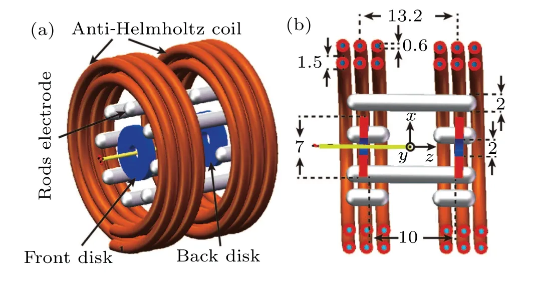
Fig. 1. (a) Schematic diagram of EMT composed of a set of an anti-Helmholtz coil, octupole electrodes, and two disk electrodes. (b) Section view of trap, together with coordinate frame and dimensions of each part.The light-yellow area indicates the passage of MgF molecules into the trap.All distances are in unit of mm.
2.2. Molecular properties of MgF
We choose MgF molecules in the X2Σ+state as a tester in our proposal out of the following considerations: (i) The MgF has an unpaired electron,leading to both non-zero electric dipole moments and non-zero magnetic dipole moments.Such molecules are important for quantum simulation, for they can be used to simulate a large variety of lattice spin models for quantum information.[26](ii) Smaller mass than other alkaline-earth monofluorides, implying less kinetic energy at the same speed thus making it easier to control. (iii)Highly diagonal Franck–Condon factors and the short lifetime for the first excited state A2Π1/2,[27]manifesting an energy level structure that is favorable for laser cooling and magneticoptical trapping.
First, we examine perturbations to the molecular structure in a pure electric field or a pure magnetic field. In pure Hund’s case (b) the molecule is of symmetry2Σ, in which the electronic spin and the resulting magnetic dipole moment are completely decoupled from the molecular axis. Thus, the electric dipole and the magnetic dipole can independently follow the external electric field and magnetic field.[23]The MgF molecule in the X2Σ+ground state conforms to Hund’s case(b)coupling,where the rotational angular momentumNcouples withSto form the total angular momentumJ,whileMis the corresponding space-fixed projection quantum number.
The total Hamiltonian is composed of the zero-field term,the interaction term between the system and the electric fieldEz, or the interaction term between the system and the magnetic fieldBz,which can be written as
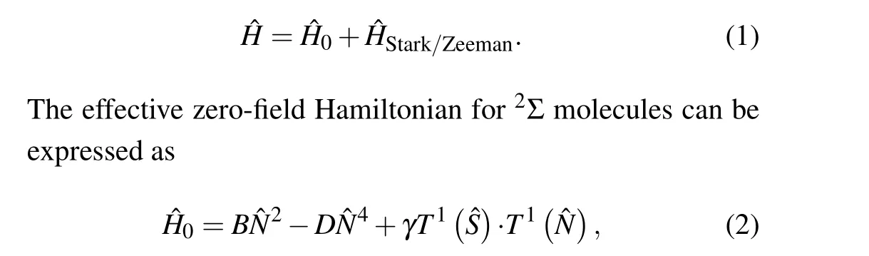
whereB,D, andγare the molecular rotational constant, the centrifugal distortion constant, and the spin-rotational coupling constant,respectively.
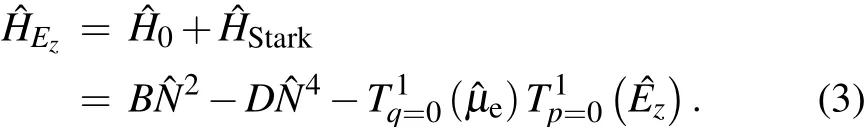
For MgF molecules in the X2Σ+state,[27]B=15496.8 MHz,γ=50.697 MHz, andD=0.0323 MHz. In the presence of a strong electric field such that ˆμeEz ≫γ,the spin–rotation interaction can be omitted,and the electric field dependent Hamiltonian ˆHEzcan be expressed as
Takingμeas the molecular dipole moment along with the internuclearzaxis(q=0),the matrix elements of ˆHEzare given as follows:

In the case of a large magnetic field,since a paramagnetic2Σ molecule has an unpaired electron, only the interaction between the electron spin and the magnetic field along thezdirection will be considered. The Zeeman energy levels are better described in terms of their decoupled projection quantum numbers,MNandMS,in which the electron spin is decoupled from the molecular frame,and quantized by the external magnetic field. This decoupling is known as the Paschen–Back effect.[28]Basis eigenwave functions in this coupling scheme are then written as|ηΛN(S)JMJ〉,while the total Hamiltonian in a large magnetic field can be expressed as
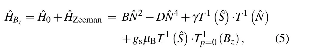
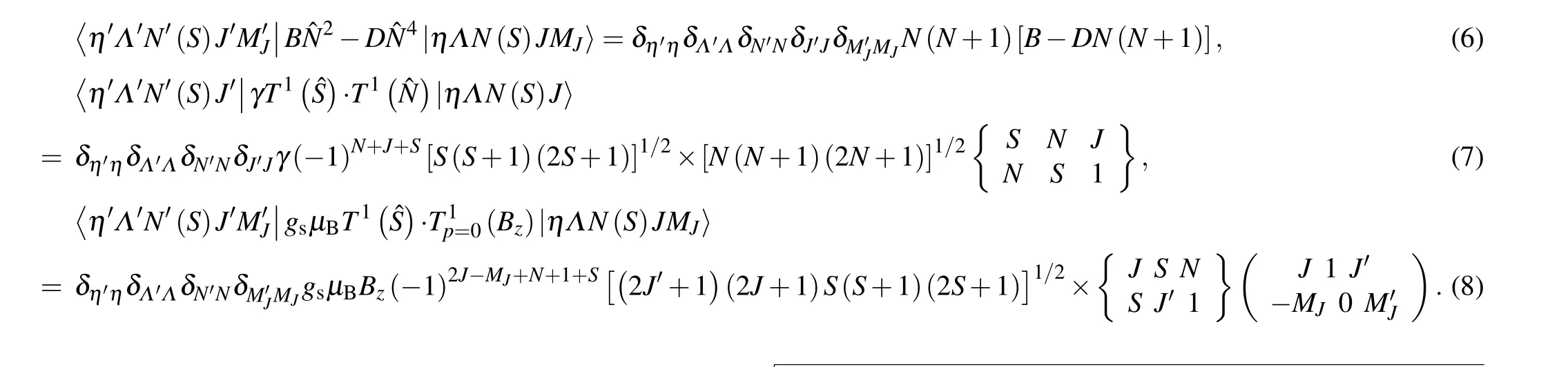
wheregsis the free-electrongfactor andμBis the magnetic moment. In Hund’s case (b) basis set, these matrix elements are presented as the rotation term (Eq. (6)), the spin–rotation interaction term (Eq. (7)), and the Zeeman interaction term(Eq.(8)).After the supersonic expansion, the rotational temperature of the molecular beam is usually several Kelvin,and most of the molecules reside in lower rotational states. The energy of the lowest rotational levels of MgF electronic ground state in the electric field or magnetic field is shown in Fig.2. The operation principle of our loading concept is similar to the principle of other electrically or magnetically trapping the molecules in a low-field-seeking (LFS) quantum state.[29]When the external field is a higher electric or magnetic field,Stark or Zeeman energy increases,so the motion of molecules in the LFS quantum state can be controlled by the gradient of field. It is important to note that the Stark shift shows the opposite behavior at a higher electric field due to the small rotational constant.Therefore,the field strength should be relatively low and kept below the turn-over point. For simplicity,it is assumed that all the molecules are populated in theN=2,MN=0,MS=1/2 state in our calculations,leading to the feasibility of manipulation for molecules of such a state in both electric and magnetic fields.
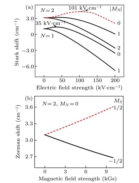
Fig. 2. (a) Stark energy levels in the lowest rotational state of the MgF molecule in the X2Σ+ state with N =2, with electric field strength of the turn-over point labelled;(b)N=2,MN =0 rotational level of MgF molecule as a function of magnetic field strength, with dashed line indicating relevant energy level used in our calculations. The unit 1 Gs=10-4 T.
The acceleration of an MgF molecule under the influence of an electric field is calculated from
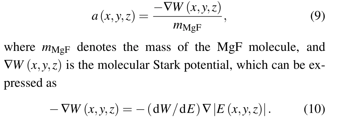
Here,-(dW/dE) is the effective dipole moment, and|E(x,y,z)|represents the magnitude of the local electric field.The method of calculating the magnetic field is similar to the above.
2.3. Loading strategy
The EMT is adjacent to the end of a Stark decelerator,which can produce the slowed-down cold molecules for the next loading into the EMT.The loading process and the trapping process are completed in four steps.To calculate the electric field and magnetic field generated by our trap,we choose maximum electric fields on axis and current parameters that are similar to the ones used in these experiments.[30,31]Figure 3 shows the distribution of electric field or magnetic field at each stage,calculated by using finite element software. Figure 3(a)shows the loading process where the front disk electrode (closer to the Stark decelerator) is grounded, and +Uand-Uare applied to the back disk and all eight rods of the octupole, respectively. In this process, MgF molecules in the LFS state will experience a repulsive dipolar force when climbing the potential hill of the electrostatic trap, which is stage I. In stage II, the molecules pass through the center of the trap and come to a near-standstill, and the front disk is rapidly switched to +U, such that a true three-dimensional(3D) trapping potential well is formed as shown in Fig. 3(b).In stage III, the synchronous molecule starts to return to the center of the well after half an oscillation period,and the copper coil is switched on and there flows a 1.5-kA current in it.The directions of the magnetic fields produced by solenoids are mutually antiparallel to each other,resulting in the formation of a quadrupole trap for confining molecules in LFS quantum states,the field distribution is shown in Fig.3(c). During this final stage of trap loading,i.e.stage IV,the currents in the coils are fast switched from 1.5 kA to 4.5 kA,and the magnetic potential well, therefore, becomes tighter than in stage III as shown in Fig.3(d),which facilitates further compression of the packet. Once the velocity of the synchronous molecule comes to 0 m/s again,all incentives will be turned off,and the molecular sample will be manipulated by other means like optical dipole forces.[32–34]In the last three stages,the non-zero minimal field strength in the trap center is beneficial to avoiding Majorana transitions,in which the LFS state molecules might transit to the HFS states and escape from the trap region.[35]
The heights of the trap barriers are shown in Figs. 3(e)and 3(f), given in K (T=WStark/k, withkis the Boltzmann constant),for MgF molecules at four stages,the potentials are calculated by diagonalizing an effective Hamiltonian that includes both Stark term and Zeeman term. The molecules do slow down when they leave the EMT center and lose the same kinetic energy as potential energy. If only the electric field was applied, the transverse well is about 0.15 K and the longitudinal trap depth reaches 1.2 K. When an additional magnetic field(4.5-kA current)is applied,the transverse trap depth reaches 0.5 K,and the longitudinal trap depth is 1.8 K,which is sufficient to trap a cold molecular packet with 20 m/s in speed.The field distribution and potential energy curves along the other transverse direction,i.e.y-axis direction,are not presented,because they are the same as those alongx-axis direction. Note that the synchronous molecule is not in the center of the well when switching to stage II,however,this allows us to perform some simple manipulations of molecules in stages III for the resulting molecular packet with higher density.
To help verify the feasibility of the loading scheme with MgF,we perform a set of 3D semiclassical Monte Carlo simulations to get molecular trajectories through the apparatus.The incident molecular number of slow MgF beam is 105,with initial distribution centered atz=-8.5 mm,vz=15 m/s,y=0 mm,vy=0 m/s, andx=0 mm,vx=0 m/s. The position distribution and the velocity distribution of the initial molecular beam are both Gaussian distributions with the 6D emittance [6 mm×6.5 m/s]×[4 mm×5 m/s]×[4 mm×5 m/s](in thez-,y-,andx-axis directions,respectively).[36,37]Molecular collision or Majorana loss plays a minor role in our manipulation, and the spin-flip loss can be reduced by using a simple external bias coil,[19]so they were not included in the simulations.[23]A package of cold MgF molecules in the X2Σ+(N=2,|MN|=0) state is produced by Stark deceleration and free flight into the trap through a small hole on the front disk in the absence of the electric field. When the synchronous molecule reaches the position where the longitudinal potential energy in stage I is minimal,the trap is switched into a loading configuration.

Fig.3. Distribution of electric field strength(in units of kV/cm)in the x–z plane with applied high voltage U =15 kV in(a)stage I and(b)stage Π;magnetic field strength(in unit of kGs)distribution when currents of(c)1.5 kA and(d)4.5 kA applied to each copper capillary;potential energy curves of MgF molecule calculated along(e)z axis and(f)x axis for four stages,with the center of the well set to be the origin of coordinates.
3. Results
Three-dimensional particle trajectory simulation is performed, and the calculated phase-space distributions of MgF molecules are sketched in Fig. 4 at four different times. Figure 4(a) shows the snapshots of the longitudinal molecular phase-space distribution at the end of the first stage. Figures 4(b) and 4(c) respectively show the phase space distribution of molecules in the second stage and third stage after oscillating in the trap for half a period. Figure 4(d) displays the phase space distribution at the end of stage IV,and figures 4(e)–4(h) indicate the corresponding transverse phase-space distributions. By precisely controlling the time of molecules staying in the potential well at each stage, we can obtain the minimum space or velocity distribution of molecules. During stage III,the synchronous molecule spends the same amount of time on the downward slop and the upward slope of the potential. Molecules ahead of the synchronous molecules take more time on the rising slope of the potential than on the falling slope, so they slow down relative to the molecules ahead of the synchronous molecule and take more time on the rising slope of the potential than on the falling slope, so they slow down relative to the synchronous molecules. Similarly, molecules behind the synchronous molecule are accelerated relative to the synchronous molecule.Therefore, a longitudinal spatial focusing is achieved. From these figures,we can see that from stage I to stage IV,the phase spatial distribution of molecules changes, so its corresponding spatial distribution will also change, which can be nicely seen in Fig. 5. At the beginning of the first stage (t=0 ms),the molecular beam is focused both longitudinally and transversely,and the spatial volume of the molecule is compressed to about 3 mm×3 mm×1.3 mm,while having a relatively large velocity spread(FWHM)of 5 m/s,5 m/s,and 33 m/s in thexaxis,y-axis, andz-axis directions, respectively. The FWHM of its longitudinal spatial distribution is 1.3 mm obtained by Gaussian fitting as shown in Fig. 5(a). When the molecules stay in stage IV for 160 μs, the spatial distribution of the molecules is further compressed to 1.8 mm×1.8 mm×1.2 mm as shown in Fig.5(d). At present,the beam velocity distribution increases to 8.8 m/s, 8.8 m/s, and 52 m/s in thex-axis,y-axis, andz-axis directions, respectively, and the beam density increases by 21.6%in our trap.The cold molecular sample with high number density and small volume is quite suitable for laser confinement and other molecular experiments such as on cold collision.
The calculated trap loading efficiency (η) is defined as the ratio of the molecular number obtained in the trap to the initial number of molecules. Figure 6 shows the load efficiency of the electric trap and the electromagnetic trap each as a function of incident velocity that isvzin the initial molecular distribution.The hole in the first disk is used as a skimmer to minimize the chance of spreading molecules entering into the trap, only part of the beam can be loaded when the incident velocity is lower,caused by the molecular spread during the free-flying stage. The higher initial velocity reduces the loading time of the molecules, thus weakening the transverse spreading and leading to more molecules in the trap. Note that for each incident velocity, in our simulation process different loading sequences with the pre-calculated optimal timings are applied to the loading and trapping. Compared with the loading efficiency of 26%when the electric field is used alone,the loading efficiency of molecules with adding a magnetic field reaches 38%,that is a 45%increase.

Fig.4. The calculated phase-space distribution of the MgF molecules at the end of each stage in((a)–(d))longitudinal direction and((e)–(h))transverse direction at the end of loading stage (t =0.826 ms), with bunch current turning on at t=1.016 ms and off at t=1.136 ms and at the end of the electromagnetic trap(t=1.296 ms),respectively,and the center of the potential well defined as the origin of the coordinates.
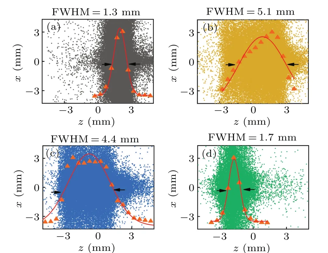
Fig.5.Longitudinal spatial fitting of molecular samples from stage I to stage IV obtained by Gaussian fitting.

Fig. 6. Calculated loading efficiency of the electric trap (yellow) and the electromagnetic trap(green)as a function of incident velocity.
4. Conclusions
In this paper, an electromagnetic trap scheme for producing 3D spatially focused cold molecular packets of stateselected is introduced. Comparing with the case using only electric fields, the number of molecular samples in the trap can increase 40%, and the molecular longitudinal length can be compressed to about a millimeter. The EMT described here provides a good early-stage preparation for the gradientintensity cooling of MgF molecules with a blue-detuned hollow beam, and the magnetic field can be relaxed or switched off in a very short time, which enables the initiation of a magneto-optical trap. Such a trap might also be a viable way of studying cold molecular collisions, quantum effect in molecular systems, and many other similar applications to those realized in atomic systems.
Acknowledgements
Project supported by the National Natural Science Foundation of China (Grant Nos. 91536218, 11874151, and 11834003), the Fundamental Research Funds for the Central Universities,China,the Program for Professor of Special Appointment(Eastern Scholar)at Shanghai Institutions of Higher Learning, China, and the Young Top-Notch Talent Support Program of Shanghai,China.
猜你喜欢
当代党员(2022年9期)2022-05-20
当代党员(2022年9期)2022-05-20
中国典型病例大全(2022年10期)2022-05-10
作文评点报·高中版(2018年39期)2018-12-26
小小说月刊·下半月(2013年8期)2013-05-14
教师·下(2009年11期)2009-12-25
文史天地(2009年11期)2009-12-09
故事会(2008年19期)2008-05-14

- Chinese Physics B的其它文章
- Dynamics of molecular alignment steered by a few-cycle terahertz laser pulse
- Terahertz spectroscopy and lattice vibrational analysis of pararealgar and orpiment
- Molecule opacity study on low-lying states of CS
- Finite-time Mittag–Leffler synchronization of fractional-order complex-valued memristive neural networks with time delay
- Ultrafast Coulomb explosion imaging of molecules and molecular clusters
- Dynamic stabilization of atomic ionization in a high-frequency laser field with different initial angular momenta