
Experimental study of the influence of annular nozzle on acoustic characteristics of detonation sound wave generated by pulse detonation engine
2022-10-26 09:46YangKang康杨NingLi李宁XiaoLongHuang黄孝龙andChunShengWeng翁春生
Chinese Physics B 2022年10期
Yang Kang(康杨), Ning Li(李宁), Xiao-Long Huang(黄孝龙), and Chun-Sheng Weng(翁春生)
National Key Laboratory of Transient Physics,Nanjing University of Science and Technology,Nanjing 210094,China
Keywords: pulse detonation engine,annular nozzle,detonation sound wave,acoustic characteristics
1. Introduction
The pulse detonation engine(PDE)has been recently recognized as an innovative aerospace propulsion technology.[1,2]It is a kind of pulse jet engine that obtains thrust by high temperature and high pressure burned products generated by the periodic detonation wave. PDEs potentially provide significant advantages of high thermal cycle efficiency, mechanical simplicity, higher thrust-to-weight ratios, lower cost, and a wide working scope.[3]The detonation sound wave is produced by the pressure pulsation of the medium caused by a series of complex waves such as shock waves outside the detonation tube and jet induced shock waves during the detonation process.[4]The preliminary research results show that the noise generated by manned aircraft with PDEs as the propulsion system is equivalent to the noise level of B–1B bombers.Therefore, when PDEs are employed as the propulsion system,the high-intensity noise and vibration generated during its operation will pose a serious threat to the aircraft’s structural sonic fatigue, overall performance, and safety. From another perspective,PDEs can repetitively and reliably generate highintensity acoustic energy. The acoustic characteristic of the detonation sound wave makes PDEs attractive for applications that require substantial acoustic energy.[5]
The nozzle is a key component of PDE’s research.[6,7]Nozzles directly affect the propulsion performance of the PDE and change the acoustic characteristics of the detonation sound wave,thereby affecting the safety of the aircraft. The annular nozzle is a type of nozzle with a relatively special structure.In the research of rocket engines, it is found that the annular nozzle has great potential for improving thrust and specific impulse performance.[8]The research on the influence of the annular nozzle on acoustic characteristics of the detonation sound wave can not only meet the fundamental research needs of PDE propulsion but is also expected to provide a new development path for the military application of pulse sound wave in special areas.
The research on the detonation sound wave was first carried out in the early 21st century, thereby, there is relatively few research in the field of detonation sound wave. The preliminary studies have confirmed that nozzles are extremely effective in the acoustic performance of PDE. Allgoodet al.[9–12]conducted an experimental study on the directivity of the acoustic characteristics of gaseous ethylene fueled PDE and explored the influence of experimental parameters such as filling fraction,ignition frequency,and nozzle structures on detonation sound wave. The experimental results showed that the sound pressure level(SPL)in upstream and sideline measurement angles is lower than the downstream angles and the overall SPL obtained an increment with fill fraction and ignition frequency increasing. The results also suggested that the acoustic characteristics are sensitive to the exit geometry,nozzle length, and area ratio. Results from the nozzle testing indicate that the converging nozzle has a global reduction in overall SPL at all fill fractions,while diverging nozzles experienced overall SPL reductions in only the downstream angles.The chevron nozzles had only a moderate effect on overall SPL.The perforated nozzle increased overall SPL at upstream angles and slightly decreased at the downstream angles. The straight cylindrical ejector had a global reduction on overall SPL at all directivity angles,and the maximum attenuation levels of 6.8 dB were observed under certain conditions. Huanget al.[13]also explored the far-field noise radiation characteristics of ejectors installed on a PDE.The experimental results also showed that ejectors could decrease the peak SPL and the maximum reduction was approximately 8.5 dB.Shawet al.[14]tested acoustic signals of the single tube to four tubes PDE fueled by hydrogen within 12 feet (1 ft=3.048×10⁻¹m), and compared the effects of five acoustic suppression designs such as converging nozzle,notched nozzles,secondary air jet,split exit,and Helmholtz resonator on SPL.Kanget al.[15]investigated the acoustic characteristics of a PDE with an ellipsoidal reflector. The ellipsoidal reflector can create a focal zone with very high pressure at the PDE axis and obviously reduce the pressure attenuation in the PDE downstream direction.
In addition to studying the acoustic characteristics of various nozzles and mufflers installed at the outlet of the PDE,the acoustic characteristics of a hybrid pulse detonation engine(HPDE), which is constituted of a compressor, a PDE, and a turbine,were also studied. Zhenget al.[16]experimentally investigated the acoustic characteristics of an HPDE under several operating conditions. The results showed that the SPL of HPDE is less than that of PDE about 4 dB,and the peak SPL reduces by about 2 dB.Huanget al.[17]conducted far field jet noise measurements of HPDE under different operating frequencies. The results showed that the turbine interacting with PDE could decrease the peak SPL approximately 14.2 dB.
In the research of the formation mechanism and propagation characteristics of detonation sound wave, Xuet al.[18,19]studied the formation and propagation process of PDE sound by combining the experimental and numerical methods. The effects of different tubes and loading conditions on PDE sound were also studied. Huanget al.[20]numerically and experimentally explored the mechanism and characteristics of noise propagation out of multiple-tube PDE.Kanget al.[21]explored the acoustic characteristics of detonation sound wave propagating in enclosed sapce. The experimental results indicated that the PSL and duration of detonation sound wave in enclosde space is higher than that in open space.
In this study, experimental investigations are performed on a gas–liquid two-phase PDE to explore the influence of the geometry of annular nozzles on the acoustic characteristics of the detonation sound wave. A PDE with diverging nozzle is also investigated as the baseline condition. The acoustic characteristics of PDE with different annular nozzles, including peak sound pressure,directivity,and A duration,are analyzed.
2. Experimental setup
The experimental system is composed of a detonation tube, fuel/oxidizer supply subsystem, an ignition device, an acoustic measurement subsystem, and various nozzles. A schematic of the experimental system is demonstrated in Fig.1.
Fig. 1. Schematic diagram of the experimental setup: 1. data acquisition and processing system,2. A/D converter,3. microphones,4. spark plug,5.ignition controller.
The detonation tube is made of a 304 stainless steel pipe which is 1700 mm in length and 80 mm in inner diameter.It consists of a mixing chamber, an ignition chamber, and a detonation chamber. A Venturi tube is installed in the mixing chamber and a spark plug is installed in the ignition chamber.A number of orifice plates are inserted into the front of the detonation chamber to accelerate the deflagration-to-detonation transition process. The 92#gasoline and nitrogen diluted oxygen are selected as fuel and oxidizer.The oxidizer used during experiments is 60% nitrogen and 40% oxygen by mole fraction. In the fuel/oxidizer supply subsystem, the compressed oxygen and nitrogen are delivered into the mixing chamber controlled by electromagnetic valves from the tangential direction. The liquid gasoline fuel in the tank is transported into an atomizing spray nozzle,which is installed at the closed end of the detonation tube, through a separate duct by nitrogen extrusion. The fuel is injected into the mixing chamber of the detonation tube after first being atomized by the atomizing spray nozzle when the electromagnetic valve of the fuel supply system is opened. Part of the fuel directly passes through the throat of the Venturi tube, and the other part of the fuel droplets are injected on the smooth surface of the Venturi tube to form a thin oil film. During oxidizer gas flow through the Venturi’s throat,gas velocity accelerates due to the contraction of the Venturi,and oil film on the Venturi surface is atomized twice. Thus, the liquid fuel and gas oxidizer are fully mixed in the mixing chamber to form a well atomized and evenly mixed combustible mixture to fill the ignition chamber and detonation chamber. The Sauter mean diameter of gasoline droplets in the mixing chamber are measured in the range of 50 μm to 100 μm. The equivalence ratio and the mass flow of the fuel and oxidizer mixture can be adjusted by controlling the filling pressure. In the present work, the filling pressure is set as 0.8 MPa and the equivalence ratio is maintained to be stoichiometric,φ=1. The fill fraction,which was defined as the ratio of the volume of the detonation tube filled with a combustible mixture prior to ignition to the overall volume of the tube, is held constant at 1.0. The fuel and oxidizer mixtures are ignited by a spark plug which delivers 1.5-J energy per spark,and the ignition frequency can be controlled easily by a signal generator. The PDE is fired at a frequency of 5 Hz in all experiments.
The acoustic measurement subsystem is specifically designed for obtaining acoustic signals.Four PCB precision condenser microphones (Model 377A12) are adopted for acoustic measurement. The dynamic range(3%distortion limit)of the microphones is 180 dB (re 20 μPa) and the microphones should be used with PCB 426B03 preamplifier. The microphones should be calibrated with GRAS 42AB sound pressure calibrator before use to determine their real-time sensitivity to avoid system errors caused by local wind speed,temperature,and humidity. The calibration accuracy of the sound pressure calibrator is 114 dB±0.2 dB (re 20 μPa). The acoustic signals are converted to a digital signal via an A/D converter and acquired by an NI PXIe-1062Q multi-channel high-speed data acquisition system at 500 k Samples/s for all microphones simultaneously by using a LabView interface program. The microphones are arranged outside the detonation tube at theθdirectivity angle at the same height as the central axis of the detonation tube, and the distance from the tube exit isr, the directivity angleθand the distancercan be changed according to the experimental requirements. The directivity angle is defined as the angle from the microphone concerning the detonation tube centerline with 0°being assigned to be the downstream direction. The microphones were arranged at directivity angles of 0°, 30°, 60°, and 90°at the positionr=10 m,15 m,20 m,and 25 m in the present study.
Figure 2 shows the geometry schematic of four nozzles explored in this study, including one diverging nozzle#1 and three annular nozzles #2, #3, and #4. The parameters are shown in Table 1. The annular nozzles are composed of an outer diverging surface and an inner cone. For the four nozzles,the inlet diameterd1is given as the diameter of the detonation tube as 80 mm and the lengthL1is kept as 300 mm.The exit diameterd2of the diverging nozzle is 220 mm. The geometry parameters of the outer diverging surface are the same as diverging nozzle #1. The length of inner coneL2remains as 300 mm,the key difference is the bottom diameter of inner coned3, which is 80, 110, and 150 mm. The ratios of inner cone diameterd3to detonation tube exit diameterd2, which is represented byDR, are 0.36, 0.5, and 0.68 separately. As shown in Fig.3,the inner cone is connected to the flange plate by the reinforcing rib, and is connected with the outlet of the diverging surface through the flange. The inlet of the nozzles are also attached to the open end of the detonation tube via a flange connection.

Fig. 2. The geometry schematic diagram of nozzles, (a) diverging nozzle,(b)annular nozzle.
Table 1. Geometry parameters of the nozzles(in unit: mm).
Fig.3. Views of the annular nozzle: (a)main view,(b)left view.
3. Results and discussion
The repeatability experiments are performed and the equivalence ratio of the fuel and oxidizer mixture,fill fraction,and the operation frequency are kept consistent in all experiments. As has been explored in previous work,[21]the detonation sound wave generated by a PDE exhibits the characteristic of typical impulse noise. As shown in Fig. 4, the detonation sound wave is mainly produced through two sources:the shock sound wave induced by the shock wave degenerated from the detonation wave and the jet sound wave produced during the blowdown of the high-temperature and highpressure detonation products.[12]
Fig.4. Schematic diagram of detonation sound wave.[5]
A typical pressure history of detonation sound wave generated by PDE with an annular nozzle is selected for analyses shown in Fig. 5. The sound pressure of the shock sound wave and the jet sound wave are represented byp1andp2respectively. The time period corresponds to the A duration is represented byt+,which would be analyzed in Subsection 3.3.
Fig.5.Typical pressure history of detonation sound wave generated by PDE with annular nozzle.
3.1. Peak sound pressure of detonation sound wave
Figure 6 shows the variations of peak sound pressure of the detonation sound wave at all directivity angles. The peak sound pressure of the detonation sound wave decays with the rise of the propagation distance at all directivity angles. However,the effects of annular nozzles on the peak sound pressure of the detonation sound wave vary with directivity angle.
As shown in Fig.6(a),the installation of annular nozzles exhibits a reduction in the peak sound pressure at 0°. The reduction effect on the peak sound pressure is most prominent under the installation of annular nozzle #4, and a maximum attenuation of 1608.7 Pa was recorded at 10 m. With the increase inDRvalue,the reduction effect of the annular nozzle gradually becomes stronger. Figure 6(b)shows the variations of the peak sound pressure at 30°. It exhibits the trend seen before at 0°,that the peak sound pressure was reduced by the annular nozzles. And the most obvious reduction effect was seen under the installation of annular nozzle#4. Here,a maximum attenuation of 1617.4 Pa was recorded at 10 m. It can be observed from Fig.6(c)that the peak sound pressure of the detonation sound wave at 60°achieved an amplification of annular nozzles#2 and#4 but a reduction of the annular nozzle#3. The amplification effect is most prominent for the annular nozzle#4,the maximum amplification condition occurs at 10 m,where an increment of 603.5 Pa is achieved. Figure 6(d)plots the peak sound pressure of the detonation sound wave at 90°. The effect of annular nozzles on peak sound pressure at 90°is opposite of the effect at 0°and 30°.As seen in Fig.6(d),the peak sound pressures are now amplified by annular nozzles, and the highest peak sound pressure is obtained when the annular nozzle #4 is installed, which increases the peak sound pressure by 881.3 Pa at 10 m. With the increase inDRvalue,the amplification effect of the annular nozzle gradually becomes stronger.
Fig.6. The effect of nozzles on peak sound pressure of the detonation sound wave at all directivity angles: (a)0°,(b)30°,(c)60°,and(d)90°.
Heet al.[22]found that the wave amplitude is much higher at the locations a little off from the centerline.They conducted numerical simulations of the external flow field of PDE. The numerical results showed the interaction between the shock wave and the vortex ring to produce the higher peak and lower trough at the locations close. The annular nozzle is composed of a diverging nozzle and a solid inner cone, and the apex of the solid inner cone is located on the centerline of the divergent nozzle. The inner cones may have a significant influence on the flow field outside the detonation tube, which changes the propagation direction of the shock wave and the following high-temperature and high-pressure detonation gas jet in the nozzle. Due to the change in the propagation direction of the gas jet,the vortex ring is developed near the outlet of annular nozzles. Under this circumstance, the vortex ring is located farther from the central axis than when no annular nozzle exists. As a result, changes in the direction of the shock wave and the position of the vortex ring lead to changes in the interaction environment between the shock wave and the vortex ring, resulting in the deflection of the position of the highest sound pressure away from the central axis.Compared with the diverging nozzle,the acoustic energy of the detonation sound wave is weakened along the tube axis and reinforced perpendicular to the tube axis by the inner cone of the annular nozzle.As the inner cone diameter(DRvalue)increases,the discharge area of the detonation products decreases,and the distance between the exit of the annular nozzle and the tube axis enlarges,which further changes the acoustic energy distribution outside the detonation tube. The case corresponding to the annular nozzle#4 with the maximumDRvalue exhibits the extremes in peak sound pressure reduction and amplification.
3.2. Directivity of detonation sound wave
A thorough understanding of the directivity of the detonation sound wave is beneficial to control the emission angle of detonation sound wave for better utilization as intensive sound equipment. To simplify the study of the directivity change of detonation sound wave,the peak sound pressure of detonation sound wave is normalized as
As seen from Fig. 7(a), the detonation sound wave with the diverging nozzle#1 at different propagation distances has the same directivity property. The peak sound pressure of the detonation wave at 30°is higher than that at another directivity angle,which indicates that the detonation sound wave of PDE with the diverging nozzle#1 has a significant directivity at 30°angle. It can also be noted that the lowest peak sound pressure is found at 90°. This suggests that most of the acoustic energy is focused near the tube axis as PDE is installed with diverging nozzle.
Fig.7. The effect of nozzles on the directivity of detonation sound wave: (a)diverging nozzle#1,(b)annular nozzle#2,(c)annular nozzle#3,(d)annular nozzle#4.
Figure 7(b)shows the directivity of the detonation sound wave with the annular nozzle#2.It can be seen that at the measuring points of 10 m,15 m,and 20 m,the peak sound pressure of the detonation wave at 60°is the highest,and its values are respectively 2.21, 3.69, and 3.78 times the peak sound pressure at 0°. At the measuring point of 25 m, the peak sound pressure of the detonation sound wave at 90°is the highest,and its value is 2.88 times the peak sound pressure at 0°. This indicates that the annular nozzle has changed the directivity of the detonation sound wave. The directivity of the detonation sound wave at the measuring points of 10 m,15 m,and 20 m is changed from 30°to 60°. The directivity of the detonation sound wave at 25 m is changed from 30°to 90°. At the same time, the annular nozzle also changed the lowest peak sound pressure from 90°to 0°.
Figure 7(c)shows the directivity of the detonation sound wave with the annular nozzle#3.It has a significant difference from the directivity of the detonation sound wave with annular nozzle#2. The highest peak sound pressure is obtained at 90°while the lowest is obtained at 0°. The directivity of 90°angle is consistent and the peak sound pressure ratios of the detonation sound wave are 4.76, 6.19, 6.04, and 4.26 at the measuring point from 10 m to 25 m,which are larger than that of the annular nozzle#2. The increase of the peak sound pressure ratio suggests that the annular nozzle #3 further reduces the acoustic energy of the detonation sound at 0°.
Figure 7(d)shows the directivity of the detonation sound wave with annular nozzle#4.The detonation sound wave with annular nozzle#4 has the same directivity as the annular nozzle #3, at a directivity angle of 90°. The minimum value of the peak sound pressure of the detonation sound wave is still at 0°, and the peak sound pressure increases gradually with the increase of directivity angle. The ratios of the peak sound pressure at 90°are further increased compared to annular nozzle#3,which are 6.51,7.59,8.46,and 8.92.The ratios of peak sound pressure are reduced at 30°compared to that of the annular nozzle#3,the ratio of peak sound pressure of detonation sound wave at 60°and 90°rises rapidly to a higher value than the value in the corresponding angle with the annular nozzle#3. It indicates that compared to the annular nozzle#2 and#3,the annular nozzle #4 further attenuates the peak sound pressure at 0°and 30°and concentrates more acoustic energy at 60°and 90°, which makes the directivity of 90°angle more prominent with the annular nozzle#4.
According to the above analysis, the annular nozzle greatly influences the directivity of the detonation sound wave.The peak sound pressure of the detonation sound wave with the annular nozzle at 30°, 60°, and 90°are all higher than that at 0°. Additionally,the directivity of the detonation sound wave also changes with theDRvalue increasing. Hence, the acoustic energy distribution of the detonation sound wave is altered by the annular nozzles,which amplify the acoustic energy in a direction perpendicular to the tube axis and weaken it along the direction of the tube axis.
3.3. A duration of detonation sound wave
Hearing impairment and loudness are both related to the acoustic energy of the detonation sound wave. The effective duration and amplitude of peak sound pressure play an equal role in evaluating the acoustic energy of impulse noise. Thus,the duration becomes another physical characteristic. The A duration is the time it takes for an initial or principal pressure wave to reach its positive peak and return to ambient pressure,which is represented byt+as shown in Fig.5. The A duration primarily indicates the amount of energy emitted by the noise source.
Figure 8(a)shows the A duration of the detonation sound wave with nozzles at 0°. The A duration of the detonation sound wave with nozzles at 0°exceeds 2 ms. Combined with the analysis of the pressure history of the detonation sound wave, it can be seen that A duration of the detonation sound wave at 0°is determined by the duration of shock sound wave induced by the shock wave degenerating from the detonation wave and jet sound wave induced by the high temperature and high pressure jet following the detonation wave. This indicates that the pressure value of the shock sound wave does not drop to negative pressure when the jet acoustic wave arrives and causes a rise in the pressure value. The effect of theDRof annular nozzles on the A duration at 0°is different. The annular nozzle #3 and #4 increase A duration of detonation sound wave while the annular nozzle #2 reduces A duration at 0°. The A duration of detonation sound wave with annular nozzle #2, #3, and #4 at 0°are gradually increased with the rise of propagation distance. This is because the detonation sound wave at 0°is attenuated by the annular nozzle,and the positive pressure is enlarged by the annular nozzle.
Figure 8(b) shows the A duration of detonation sound wave at 30°. The A duration of the detonation sound wave at 30°is distributed in the range of 0.4 ms to 0.7 ms and 2.5 ms to 3.1 ms.The A duration of detonation sound wave with annular nozzle #4 at all measuring points are determined by both the shock sound wave and the jet sound wave,so as the detonation sound wave with annular nozzle#3 at 10 m and 15 m. In these circumstances, the A duration of the detonation sound wave ranges from 2.5 ms to 3.1 ms.The A duration of the detonation sound wave with diverging nozzle#1 and annular nozzle#2 at all measuring points are determined by the shock sound wave only,so as the detonation sound wave with annular nozzle#3 at 20 m and 25 m. As a result,the A duration of the detonation sound wave under these conditions is relatively short, in the range from 0.4 ms to 0.7 ms. The annular nozzles increase the A duration of the detonation sound wave at 30°. The A duration of detonation sound wave with annular nozzles at 30°is decreased gradually with propagation distance increases. The reason is that the acoustic energy of the detonation sound wave with annular nozzles at 30°has been enhanced. As the propagation distance of the detonation sound wave increases, the peak sound pressure of the shock sound wave attenuates. This results in the time interval between the shock sound wave and the jet sound wave being shortened,thus reducing the A duration.
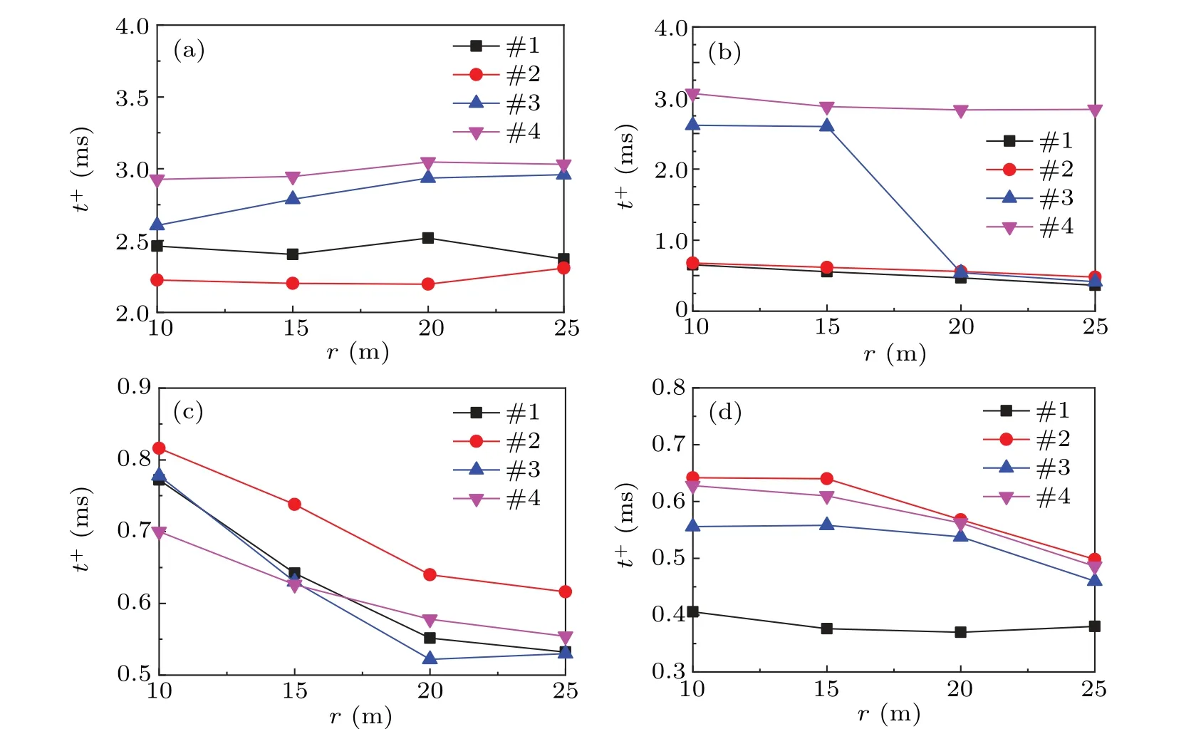
Fig.8. The effect of nozzles on A duration of detonation sound wave.
Figure 8(c)shows the A duration of the detonation sound wave with nozzles at 60°. The A duration of the detonation sound waves with nozzles at different propagation distances at 60°are all in the range from 0.5 ms to 0.9 ms. The A duration of the detonation sound wave with annular nozzles at 60°is only determined by the shock sound wave,and it gradually decreases as the distance increases.
Figure 8(d)shows the A duration of the detonation sound wave with nozzles at 90°. The A duration of detonation sound wave at 90°is distributed in the range from 0.3 ms to 0.7 ms.The annular nozzles#2,#3,and#4 increase the A duration at 90°. The A duration of the detonation sound wave with annular nozzles at 90°also decrease with increasing propagation distance of the detonation sound wave.
It is clear from the above analysis that annular nozzles influence the A duration of the detonation sound wave. The A duration increases with the propagation distance at 0°and decreases with the propagation distance at 30°,60°,and 90°.The most important finding is that annular nozzles can increase the A duration of detonation sound wave at 90°.
4. Conclusions
In this study, the influence of the geometry of the annular nozzle on acoustic characteristics of a PDE is experimentally investigated. Experimental results demonstrate that the annular nozzles can amplify the peak sound pressure of the detonation sound wave at 90°while reducing it at 0°and 30°.The lowest peak sound pressure of the detonation sound wave with the annular nozzle occurs at 0°. The annular nozzles can also shift the directivity of the detonation sound wave from 30°to 90°. The annular nozzles can increase the A duration of the detonation sound wave at 90°. The changes of the acoustic characteristics of detonation sound waves demonstrate that the acoustic energy distribution of the detonation sound wave is altered by the annular nozzles,which amplify the acoustic energy in a direction perpendicular to the tube axis and weaken it along the direction of the tube axis. When PDEs are employed as high-intensive sound sources,the annular nozzles can assist PDEs in generating the high-intensity sound wave and emit it in multiple directions regardless of the fixed installation location.The research results can promote the mechanism research of PDE’s acoustical problems and provide experimental verification for the military application of detonation sound waves.
Acknowledgements
Project supported by the Natural Science Foundation of Jiangsu Province, China (Grant No. BK20220919) and the National Key Laboratory of Transient Physics Foundation Project,China(Grants No.6142604210203).
猜你喜欢
现代交际(2022年6期)2022-06-20
动漫界·幼教365(小班)(2022年4期)2022-03-27
文萃报·周二版(2020年16期)2020-05-11
收藏与投资(2020年12期)2020-04-18
收藏与投资(2020年12期)2020-04-18
名人传记·财富人物(2017年5期)2017-06-10
名人传记·财富人物(2017年5期)2017-06-10
商界评论(2017年5期)2017-05-17
健康必读(2016年11期)2016-12-12
杂文选刊(2014年12期)2014-11-17

- Chinese Physics B的其它文章
- Formation of high-density cold molecules via electromagnetic trap
- Dynamics of molecular alignment steered by a few-cycle terahertz laser pulse
- Terahertz spectroscopy and lattice vibrational analysis of pararealgar and orpiment
- Molecule opacity study on low-lying states of CS
- Finite-time Mittag–Leffler synchronization of fractional-order complex-valued memristive neural networks with time delay
- Ultrafast Coulomb explosion imaging of molecules and molecular clusters