
Analytical Models of Concrete Fatigue:A State-of-the-Art Review
2023-01-22 08:59XiaoliWeiMakhloofandXiaodanRen
Xiaoli Wei,D.A.Makhloof,2 and Xiaodan Ren,★
1College of Civil Engineering,Tongji University,Shanghai,200092,China
2Department of Civil Engineering,Minia University,EL-Minia,61111,Egypt
ABSTRACT Fatigue failure phenomena of the concrete structures under long-term low amplitude loading have attracted more attention.Some structures,such as wind power towers,offshore platforms,and high-speed railways,may resist millions of cycles loading during their intended lives.Over the past century, analytical methods for concrete fatigue are emerging.It is concluded that models for the concrete fatigue calculation can fall into four categories:the empirical model relying on fatigue tests,fatigue crack growth model in fracture mechanics,fatigue damage evolution model based on damage mechanics and advanced machine learning model.In this paper, a detailed review of fatigue computing methodology for concrete is presented,and the characteristics of different types of fatigue models have been stated and discussed.
KEYWORDS Concrete; fatigue lifetime; fatigue crack growth; fatigue damage evolution; machine learning
1 Introduction
It is inevitable for concrete structures to bear fatigue loads during their lifetime.With the development of material science and technology, the fatigue stress level acting on concrete gradually increases.Due to the high amplitude and frequency of fatigue loads, the fatigue problem is prominent, particularly on new concrete structures such as wind power towers, offshore platforms,and high-speed railways.For example, Fig.1 shows that the reinforced concrete foundation of a wind turbine tower cracked due to long-term fatigue loads.In order to ensure safety, the research on fatigue of concrete is of vital importance in structural engineering.Over the past century,significant and considerable efforts have been made to develop analytical and numerical methods for concrete fatigue.Tests show that a number of loading cycles will lead to structural failure due to energy dissipation with each loading cycle, and there are hysteresis loops in the stress-strain curve, as shown in Fig.2.The fatigue lifeNf, defined as the number of the load cycles at failure,decreases with the increase of the fatigue stress amplitude, as shown in Fig.3.The traditional approach is to obtain the empirical models from fatigue tests for design, and the representative ones areS-Ncurves andP-Mrules.Besides, the response of concrete under fatigue loading exhibits three stages:rapidly increasing, then decreasing to a steady-state, and finally increasing sharply to failure, as indicated in Fig.4.So, solid mechanics can be employed to simulate the fatigue process of concrete.It can be divided into two categories:fracture mechanics and damage mechanics.Fracture mechanics is used for simulating how the fatigue crack grows and develops,while damage mechanics is used to reproducing the deterioration process and response of concrete under fatigue loading.Recently, deep learning models have been introduced to evaluate the fatigue life of the concrete.
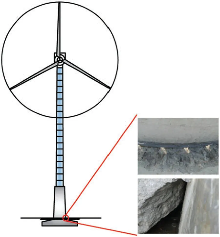
Figure 1:The destroyed foundation of a wind turbine tower under long-term fatigue loads
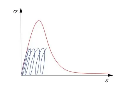
Figure 2:The energy dissipation under fatigue loading
This research is organized as follows.Some experimental fatigue models, includingS-Ncurves and empirical failure criteria, are presented in Section 2.The solid mechanics models for studying concrete fatigue, which can be divided into fracture mechanics and damage mechanics are discussed in Sections 3 and 4, respectively.The application of machine learning to concrete fatigue research is briefly introduced in Section 5.Finally, Section 6 summarizes some conclusions.In the following sections, the characteristics of every fatigue analysis model for concrete will be illustrated and discussed in detail.
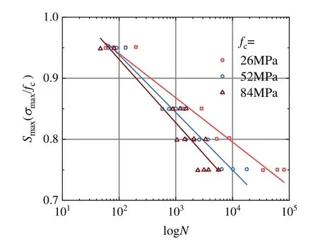
Figure 3:The relationship between the fatigue life and the stress level (data from literature [1])
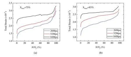
Figure 4:The variation trend of concrete response under the fatigue load (data from literature [1])
2 Empirical Models Based on Experiments
2.1 S-N Curves
2.1.1 Compressive Fatigue
In general, experimental research has been used to investigate any engineering phenomena.Since the importance of structural fatigue has been recognized, fatigue tests have been carried out, and some empirical models to reflect the fatigue laws of concrete have been established.In 1870, after a systematic study on the fatigue failure of a train wheel, Wöhler [2] proposed Wohler’s law, which reflects the relationship between the stress levelSand the number of load cyclesN, which is known as theS-Ncurve.Accordingly, many fatigue tests of concrete were carried out by researchers, and theS-Ncurves of concrete were fit based on the test data.The earliest concrete compression fatigue test can be traced to the early 20th century [3,4].Since the 1970s, experimental research on the fatigue performance of concrete under uniaxial compression has been systematically explored.In 1973, a formula of compressionS-Ncurves for concrete was proposed by Aas-Jakobsen et al.[5] and modified by Tepfers et al.[6] as a linear relationship in the semilogarithmic coordinate system, and it was expressed as follows:

where fatigue strengthSis the ratio of the maximum stressσmaxto the material static strengthfc,Ris the ratio of the maximum stressσmaxto the minimum stressσmin,Nis the ultimate fatigue life,βis a constant, usuallyβ=0.064 ~0.080.Eq.(1) has been considered to be a classical expression to describe the uniaxialS-Nrelationship of concrete, which was widely used [7] and adopted in design codes later.Besides, theε-Ncurves were also established by Wang et al.[8]in which the corresponding stress term in Eq.(1) was replaced by the strain levelεmaxand the strain ratioR=εmin/εmax.
On this basis, the effect of loading rate on the fatigue life of concrete was noted and studied [9–11].It was indicated that with the increase of loading rate, the fatigue life of concrete at a certain stress level would increase.In order to consider the rate effect on fatigue performance,the loading periodTwas introduced into the expression of Eq.(1) by Hsu et al.[10], and the different expressions of high-cycle fatigue and low-cycle fatigue were expressed as follows:
· High cycle fatigue (103~107cycles)


· Low cycle fatigue (1 cycle ~103cycles)The parameters in Eqs.(2) and (3) have been taken as the exact meanings of the original formula in Eq.(1).
In addition, the research on the compression fatigue performance of high-strength concrete indicated that the fatigue strength would decrease with the increase of the static strength [1,12–14].Based on test results, a formula forS-Nrelationship considering concrete strength was proposed by Kim [1]:

wheref1=1.0 MPa,f′cis the static compressive strength,k1,k2,n,mare parameters, which can be evaluated experimentally.
2.1.2 Tensile Fatigue
Owing to the significant difference between the tensile and compressive characteristics of concrete, the experiments of tensile fatigue were performed through the indirect splitting test [15]and the direct tensile test [16–18].It is more complex to carry out the tension fatigue tests of concrete than compression fatigue tests because the eccentricity of loading in pulse tension test is easy to occur, which is difficult to deal with even for static loading.Moreover, special test equipment and specimen shape are required in the tension test.Thus, the results of tensile fatigue tests are relatively small.In 1979, the same formula of the tensionS-Ncurves as Eq.(1) was obtained by Tepfers [15] through splitting tensile test, in which the parameterβ=0.0685.Usually,the members would bear the reversal tension-compression stress under the repeated external load.The influence of stress reversal on the tensile fatigue strength was investigated through tension and tension-compression fatigue tests by Cornelissen et al.[18].The results showed that stress reversal could reduce tension fatigue life.Consequently, the expressions of the tensileS-Ncurves were given as follows:
· Tension fatigue (σmax≥0)

· Compression-tension fatigue (σmax<0)

whereftandfcare the static tensile strength and the static compressive strength of concrete,respectively.
2.1.3 Multi-Axial Fatigue
In practice, materials are probably subjected to a multi-dimensional stress.The current test research of the multi-dimensional fatigue loading is relatively scarce.In this regard,the biaxial fatigue tests have been performed and presented [19,20], besides the axial fatigue testes with lateral confinement [21–26].It could be observed that the compressive fatigue strength of concrete would increase while the tensile fatigue strength would decrease under lateral confinement.In addition,the expression of theS-Ncurves with lateral confinement was given by Hooi [21] as follows:

in whichα=1+K1(σ1/fc),K1=3.8 ~4.1,β=0.5(σ1/fc)+0.08,σ1is the effective confining stress andfcis the unconfined concrete strength.
In order to consider the great discreteness and randomness of concrete fatigue life, the fatigue strength under a certain failure probabilityPwas studied in the statistical probability method [27].The empiricalS-N-Prelationships between stress level (S), number of cycles (N), and failure probability (P) were fitted [28–30].In addition, fatigue tests of new materials, such as high-strength concrete [1,31], fiber-reinforced concrete [32], recycled aggregate concrete [33], and so on, also were carried out.It is worth noting that the main objective of the early research on concrete fatigue was to obtain the quantitative relationship between fatigue life and fatigue stress by several tests.Indeed, it’s convenient to calculate the fatigue life under a given stress level withS-Ncurves.Due to the large discreteness of concrete fatigue experiments, a large number of experiments are needed to obtain theS-Ncurves.However, most of the conclusions obtained are inadequate to cover all the different cases, particularly in the complex stress field; no unified conclusion is universally accepted.
2.2 Empirical Fatigue Failure Criteria

In order to give an index to judge fatigue failure, some phenomenal fatigue damage accumulation models are developed.It is assumed that damage is accumulated linearly with the number of the load cycles, and the fatigue damageDis defined as the sum of the ratio of the load cyclesNito the fatigue lifeNfi[34–36], known as theP-Mrule.The mathematical form of theP-Mrule was expressed by Miner [36] as follows:in whichCrepresents theC-th fatigue stress level, andNiandNfirepresent the number of load cycles and the fatigue life atSistress level, respectively.P-Mrule can be used in the case of multi-level constant amplitude fatigue loads.Eq.(8) means that fatigue failure occurs whenD=1.TheP-Mrule had been recommended by the AASHTO LRFD code [37] for the bridge design and was adopted widely in fatigue analysis of the bridge engineering [38–40].TheP-Mrule can also be chosen as a constraint condition in the structural topological optimization problem[41,42].It is obvious that theP-Mrule does not take the effects of the load history and the load sequence into account.Consequently, theP-Mrule was modified into nonlinear forms by several scholars [43–46], as shown in Table 1.
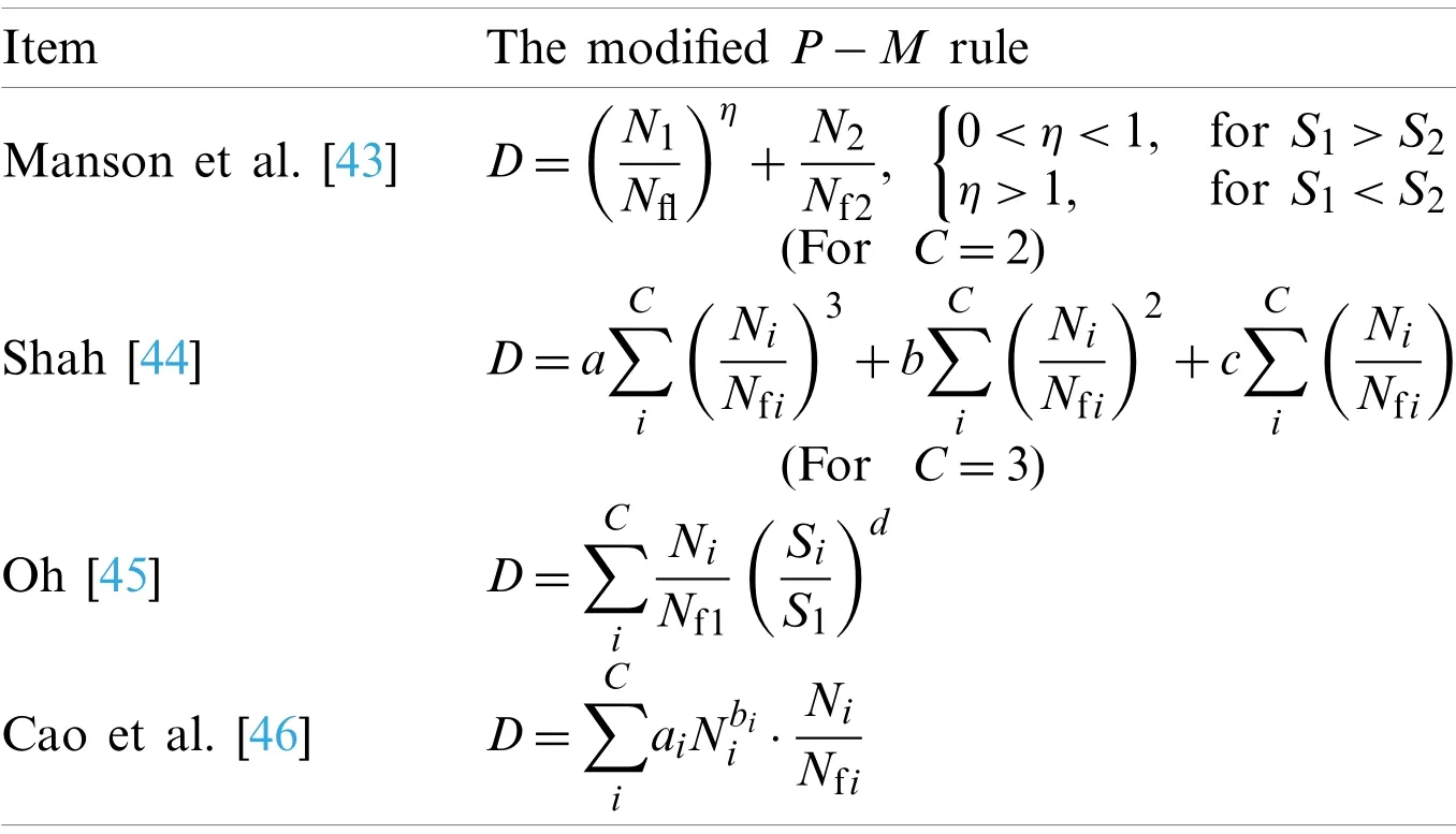
Table 1:The modified P-M rules of the nonlinear fatigue damage for concrete fatigue
Although the improvedP-Mrules consider the nonlinearity of damage accumulation associated with the loading history, it is still limited to concrete material and difficult to extend to fatigue prediction of the whole structure.The premise of using theP-Mrule is that the ultimate fatigue lifeNfof the structure has been known.The ultimate fatigue lifeNfis acquired fromS-Ncurves, in which the stress is still calculated by the linear elastic theory.Undoubtedly, irreversible deformation and stiffness degradation will occur in the process of fatigue loading, resulting in stress redistribution, which involves non-linear elastic process.TheP-Mrule has no ability to get the damage distribution and other responses of the structure subjected to fatigue loading.
It can be concluded that the fatigue research presented in this section is focused on the fatigue performance of concrete material level.Also, several types of research have been carried out on the fatigue of the concrete beams [47–55] and slabs [56,57].Structural fatigue is affected by many factors, such as reinforcement ratio, shear span ratio, concrete strength, and so on.Only some qualitative conclusions were drawn, and there are no united and universal design standards for fatigue of concrete structures.The limit state method or the allowable stress method are still used for the design of concrete structures subjected to fatigue loads, which means that stress redistribution during loading cannot be considered.
3 Fracture Mechanics-Based Fatigue Models
This section introduces the application of fracture mechanics methods in concrete fatigue.Due to the fact that the concrete is a complex composite material, the micro-cracks are initiated and propagated during the curing process.Consequently, the expansion and accumulation of these micro-cracks under fatigue loading lead to the generation of macro-cracks, which causes fatigue fracture of concrete.Thus, the theories of fracture mechanics describing crack propagation were initially introduced to investigate the growth of the fatigue crack.The more commonly used methods include Paris’law and the cohesive crack model.
3.1 The Modified Paris’Law for Concrete
Paris’law based on linear elastic fracture mechanics gives the fatigue growth rate at the crack tip.In 1962, a formula describing the propagation rate of fatigue crack was proposed by Paris et al.[58], known as Paris’law, and it was expressed as follows:

wherearepresents the crack length,Nis the number of cyclic loads,ΔK=Kmax-Kminis the amplitude of the stress intensity factor,Candmare constants.The Paris’law had been mainly used in the metal fields [59–63].Some bending experiments of notched concrete beams [64,65]were carried out to investigate the parameters in Paris’law applicable to plain concrete.However,because of the inhomogeneity and the initial micro-defects, it was thought that Paris’law needs to be modified.The bending tests of notch beams by Wu et al.[66] showed that the average of the fatigue load has a great influence on the crack growth rate.So, a formula of the fatigue crack propagation rate was given considering the ratio of the minimum to the maximum of the stress intensity factor as follows:

in whichR=Kmin/Kmax,KIcwas the fracture toughness, andCandnare the constants.In addition to the fracture toughness, the load history and the size of the crack were also taken into account, and the modified Paris’law was proposed by Slowik et al.[67] and presented as follows:

whereKIsupis the maximum stress intensity factor reached in the loading history,F(a,Δσ)is a function representing the effect of overloads in whichais the length of the crack, andΔσis the amplitude of the stress.After, the expression of the coefficientCin Eq.(11)vs.loading frequency and the relative size of the fracture zone was given by Sain et al.[68] through regression analysis of the previous experimental results.
It is found that the growth of fatigue cracks could also be affected by the concrete specimens sizes [49,69,70].The size effect on the crack growth was studied in [69,70], and a size-adjusted Paris’law was proposed as follows:
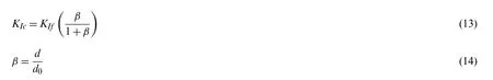
whereKIcis the size-adjusted fracture toughness,KIfis the asymptotic value of fracture toughness for an infinitely large specimen,dis the depth of the specimen, andd0is a constant characterizing the specimen geometry.Compared to Eq.(9), a normalized stress intensity factor was adopted in the size-adjusted Paris’law, and the normalization rule is related to the size of the specimen.Then, the discoveries of Kolluru et al.[71–73] were that the crack growth rate decreased first and then increased.The critical crack length where the rate of crack growth changed from deceleration to acceleration was the crack length at the peak load of the quasi-static response.Two mechanisms governing the crack growth rate were assumed:the crack growth is governed by the increasing resistance in the deceleration stage, and the Mode I stress intensity factorΔKin the acceleration stage.Hence, the bi-law of the fatigue crack propagation rate was proposed by Kolluru et al.[71]as follows:
· In the deceleration stage (a <acrit)

· In the acceleration stage (a≥acrit)

whereacritis the critical length at the peak load of the quasi-static response,Δa=a-a0,ais the length of the crack, anda0is the initial length of the crack.
Since concrete is a composite complex material, the path and shape of concrete crack surface are random when concrete material cracks.Therefore, some fractal theories and self-similarity methods were introduced to explain the propagation of the fatigue crack and improve the Paris’law [74–76].However, it was only an approximation means, and there was minor progress in promoting the modified Paris’law to apply to the concrete fatigue crack.
It should be noted that Paris’law is concerned with the existing small cracks, in which the crack initiation cannot be considered.Because the stress intensity factor is only applicable to the near-tip zone of the crack, the use of the linear elastic fracture mechanics requires that the crack zone be very small compared with the dimensions of the specimen.With the crack propagation,the stress intensity factor is no longer dominant.
3.2 The Cohesive Fatigue Crack Models
It is generally believed that the nonlinearity of concrete crack tip should be considered.In the 1970s, the fictitious crack model was proposed first by Hillerborg et al.[77] to reflect the nonlinear characteristics of materials in the fracture process.The fictitious crack model, which is also usually called the cohesive crack model, contributes to using the finite element method in complex fracture problems.A certain number of assumptions had been made to apply the cohesive crack model to fracture analysis of concrete material [78,79].Firstly, it is assumed that a fracture zone can transfer traction at the crack tip.Secondly, it is assumed that before the ultimate strength of the material is reached, the concrete is elastic, and if the principal tensile stress exceeds the ultimate strength, the concrete materials start to crack, and the tensile stress also starts to decrease.The stress transfer ability depends on the crack opening displacementωat the crack tip.Thirdly, if the critical widthωcof the crack is exceeded, concrete is completely fractured, and the stress is reduced to zero, as shown in Fig.5.It can be seen that the first step of using the finite element method to simulate cohesive fracture of concrete is to establish stress-COD (crack opening displacement) relationship.
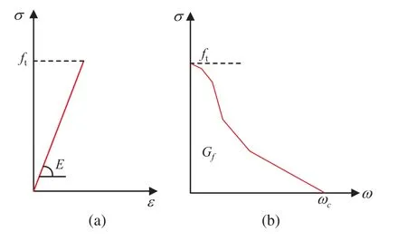
Figure 5:(a) The curve of σ-ε at elastic stage of the cohesive crack model; (b) The curve between the stress σ and the crack opening displacement ω, of the cohesive crack model
Initially, the cohesive crack model was mainly used for the cracking process under monotonic loading.The cohesive crack model was first used to explain qualitatively how fatigue crack extends and how the stress at the tip changes by Reinhardt [80], illustrated as Fig.6.Assume a crack with lengtha(N)afterNloading cycles, and the softening zonec(N)has developed in front of the crack, as shown in Fig.6a.After the external force is completely released, the part with too large strain cannot be completely recovered.The stress at the crack tip will not disappear but remains self-equilibrium, as shown in Fig.6b.During the next loading cycle, the stress in the softening zone reduces due to the influence of unloading, and the softening zone should spread a little in order to ensure equilibrium, as shown in Fig.6c.In a following cycle, the same procedure is repeated, and the softening zone will extend forward, as shown in Figs.6d and 6e.Along this simple physical model, the stress-COD envelopes and the hysteresis relationships were needed for the numerical simulations.For example, a trilinear stress-strain envelope and the straightline unloading-reloading paths in each stage, as shown in Fig.7, were assumed by Gylltoft [81]to simulate the progressive fracture of the notched beams of plain concrete subjected to cyclic loading.However, this is inadequate to describe more failure modes.
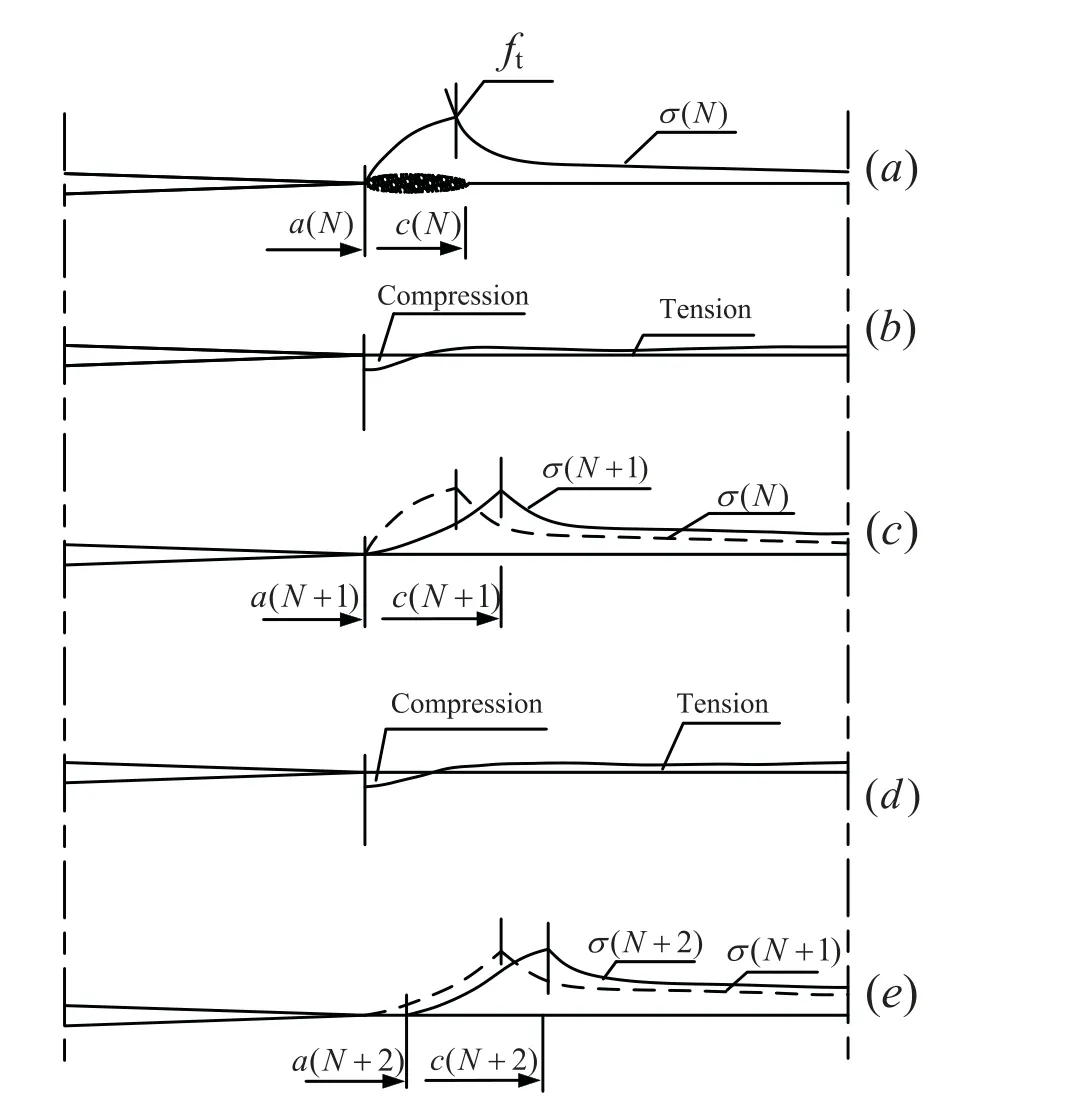
Figure 6:Fatigue crack growth of quasi-brittle material during cyclic loading [80]
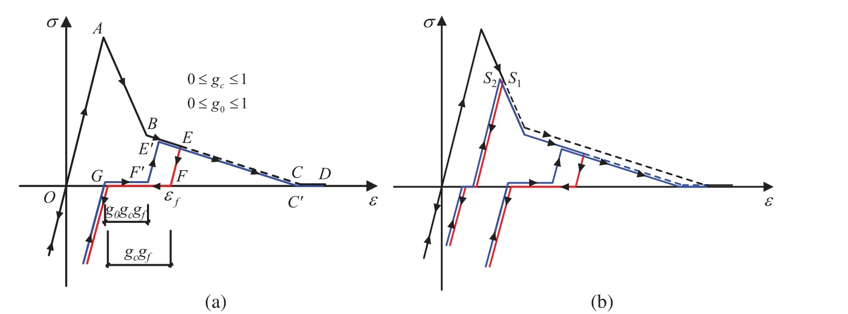
Figure 7:The model of fatigue stress-crack opening displacement by Gylltoft
In order to obtain better stress-COD curves, monotonic loading and cyclic loading tests were carried out [82,83].The widely used expression of theσ-COD envelope at the crack tip is expressed as follows [82]:

wherec1andc2are constants.In addition, a detailed focal point model describing the path of unloading and reloading was proposed by Yankelevsky and Reinhardt [83] based on the observations of stiffness changes in a specific cycle, as shown in Fig.8.In this model, multiple lines were used to specify the relationship between stress and crack opening displacement at the crack tip during the process of loading-unloading-reloading.The focal model presents a cyclic approach which is closer to the actual behavior.Since the construction of the focal model needs to follow the complex rules to determine many special points, it is inconvenient for the implementation of the finite element analysis.Assume that the curve during an unloading-reloading cycle would not return to the same point of the envelope curve where it started to unload but to a point with lower stress, and the gap between the unloading point and the returned point can be explicitly given.The four expressions for cyclicσ-COD in the softening zone were suggested in [84], including the envelope curve using Eq.(17), the unloading curve (I), the gap in the envelope curve (II), and the reloading curve (III), as shown in Fig.9.
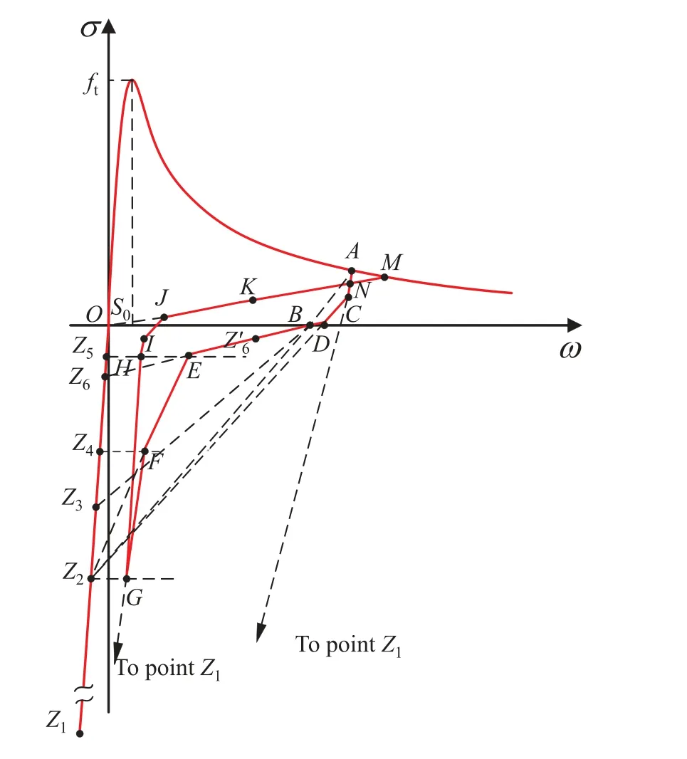
Figure 8:The focal model by Yankelevsky and Reinhardt
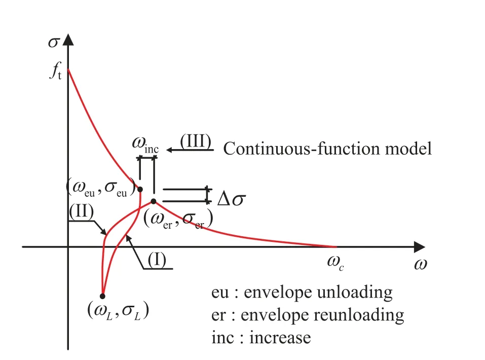
Figure 9:The Hordijk’s model
Due to the complexity of the hysteretic model and the time-consuming in finite element analysis, the fatigue constitutive relationship of the crack tip had been simplified [85,86].For example, the unloading-reloading path in the mentioned Hordijk’s model was simplified as three straight lines in [86].
Based on the mentioned nonlinear fracture mechanics-based models, it can be indicated that nonlinear fracture mechanics could explain the process of concrete fatigue crack growth in detail.The fracture mechanics model was mainly used to analyze the fatigue growth characteristics of one or a few macro-cracks in members.In the finite element analysis, the cohesive elements must be set in advance along the fracture zone.The nonlinear property is used in the element of the fracture zone with the dense discretization, while the linear property is still used in the main body.But, there are many initial micro-cracks and micro-defects in the concrete’s interior.The cohesive crack model is difficult to describe the propagation and aggregation process of a large number of randomly distributed micro-cracks under the fatigue load.
4 Damage Mechanics-Based Fatigue Models
From the test results [14,87,88], the response of concrete under fatigue loading has obvious three-stage characteristics.For example, the total strain growth of concrete under constant amplitude fatigue load can be divided into three stages:the rapid increase at the first 10% of life, the stable development during the 10%~80% of the life, and then the sharp increase until failure,as shown in Fig.10.The deterioration of elastic modulus also includes three similar stages, as shown in Fig.11.The mentioned methods seem to be unable to obtain the response of the whole process under high-cycle and low-amplitude fatigue loading.
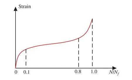
Figure 10:Increase of the compression strain with loading cycles
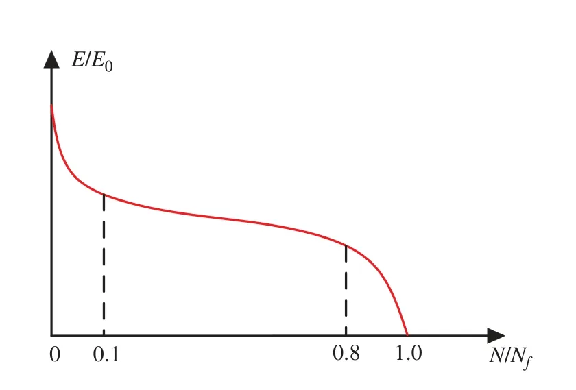
Figure 11:Degradation of the elastic modulus with loading cycles
As a branch of solid mechanics, damage mechanics is mainly used to study the degradation of macro-mechanical properties of material caused by the generation and expansion of internal micro-defects.This section reviews the development of fatigue damage theories.

In the damage mechanics, the constitutive equation can be expressed as:Damage variable D is the fourth-order tensor which can be regarded as the internal variable,E0is the fourth-order stiffness tensor, and the symbol “:” is the contraction of tensors.It is very important to determine a damage criterion.The classical damage mechanics was greatly inspired by the classical plastic mechanics theory.The damage potential functionG(f)was introduced [89],as follows:

wherefis the gauge function.According to the orthogonal flow criterion, the evolution of the damage variable can be taken as follows:


Eq.(21) indicates that when the stress state isn’t beyond the damage surface, the damage will not increase regardless of the external loads change.Fatigue load can be divided into low cycle fatigue and high cycle fatigue loads according to the number of load cycles.The low cycle hysteretic behavior of structures under seismic loads has been easily obtained using the general damage model [90–92] or the construction of the hysteretic constitutive model [93–95].This section pays attention to the models for concrete structures under high-cycle fatigue loads.The stress state under high-cycle fatigue loading might always be within the damage surface, which means that there is always no damage evolution if the static damage model is adopted.Actually, fatigue loads could lead to damage accumulation of concrete even if the stress state is lower than the damage surface.When the hysteretic energy dissipation accumulates to a certain level, the structure will fail.Therefore, when it comes to the performance of structures under high cycle fatigue loads, the static model no longer has good predictability.To overcome the drawbacks of the conventional damage criterion, there are two approaches to solve the accumulation of fatigue damage.One is the bounding surface theory [96–98], and the other is fatigue loading-unloading criterion [99,100].
Not very long after, the Princess had a baby, a little boy, but when the King her father heard of it he was very angry and afraid, for now the child was born that should be his death
In the bounding surface theory [97], a limit fracture surface (LFS), a boundary surface (BS),and a loading surface (LS) changing with loading history were defined, as shown in Fig.12.The damage begins to increase only when the loading surface under fatigue loading is outside the limit fracture surface and expands towards the direction of the boundary surface.The damage growth rate is related to the distance between a point on the loading surface and the corresponding mapping point on the boundary surface.In finite element calculations, many iterations and corrections are required, which will be time-consuming.
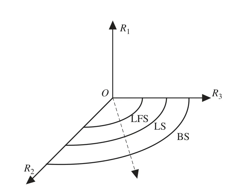
Figure 12:The limit fracture surface, the boundary surface, and the loading surface in Suaris’model
The fatigue loading-unloading criterion was proposed by Marigo [99] to judge whether fatigue damage evolves or not.The loading-unloading irreversibility concept not only can capture the damage accumulation within the damage surface but also is simple to apply.This concept means that the internal fatigue damage variables of concrete only increase in the rising stage of every load cycle.Interestingly, there are similar models in the study of the fatigue response of other materials [101].Here, the damage consistency parameter was directly expressed as:

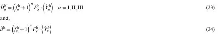
For a complete damage constitutive relationship, reasonable fatigue damage evolution laws are also very significant.The form of damage variable can be divided into the single scalar damage[102–107] and the anisotropic tensor damage [100,108–112].The evolution of the single scalar damage under high-amplitude and low-cycle fatigue loading can be simply calibrated by the tests and accurately simulate the uniaxial hysteretic behavior of concrete [104,105,113].The single scalar damage models are weak to reproduce fatigue response of concrete structures subjected to the high-cycle and low-amplitude fatigue loads, as well as multiaxial stress.Actually, the anisotropic damage model is more consistent with the anisotropic mechanical properties of concrete.The earliest anisotropic fatigue damage model for concrete was extended by Papa et al.[100] from the anisotropic static damage model.The total damage was decomposed into a second-order symmetric damage tensor D in deviatoric strain space and a scalar damage variabledin volumetric strain space.The evolutions for each component of damage are as follows:in which the sign “h”is c for compression and t for tension, the sign “α”represents each principal direction, and “v”means volumetric component,fis gauge function, the variablesYconjugate to each damage variable in the Helmholtz free energy were selected as damage driving force,Fis the function ofY, andnis the parameter.This anisotropic model considers two types of anisotropy,one is the difference between tension and compression, and the other is the difference in each direction.Moreover, the coupling between components is neglected.In this case, there are some more simplified models developed.
It is assumed that the fatigue damage of concrete is mainly driven by tensile strain, and the evolution rate of the fatigue damage tensor was expressed in [108] as follows:

wheren,K, andC1are the material parameters, tr(·) represents the trace of the tensor.Actually,compression also has a great influence on the initiation and growth of crack and should be taken into account the damage evolution.
Some bi-scalar elastoplasticity fatigue damage models for concrete were extended [109–111]in the frame of the static damage model [114–116].In the bi-scalar damage model, the effective stress is split into positive and negative parts.The positive part is tension, and the negative part is compression.An isotropic scalar damage is assumed in the tension and compression space.Thus,the anisotropic damage is mapped into two isotropic spaces by the mapping tensors as follows:

in whichd±are the scalar damage variables in the tension and compression, respectively, and P±are the mapping tensors.There are two approaches to bi-scalar damage modeling, the phenomenological continuum model [109] and the physically mesoscale stochastic fracture model[110,111,117].A continuum fatigue damage evolution, similar to Eq.(22) in form, is proposed by Liang et al.[109] as follows:

whereκ±,n±, andC±are the parameters,h±(d±) represent a mechanism of competition between the damage healing effect and the damage driving effect, corresponding to the three stages of fatigue damage increasing rate, and are expressed as follows:

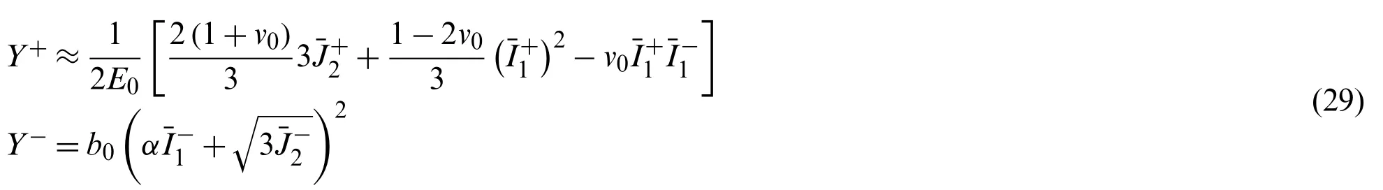
whereare the positive and negative component of the effective stress tensor,E0is the initial elastic modulus, andandare respectively the first and second invariant of,ν0is poisson’s ratio,b0is a material constant.The inherent randomness objectively existing in concrete is not reflected in the continuum damage model.A stochastic fracture model with the spring bundle, as shown in Fig.13, can explain the relationship between the mesoscale randomness and the macroscale nonlinearity of concrete [115].The rate process theory [119] was applied to investigate the fatigue energy dissipation, and the fracture caused by the fatigue energy dissipation was incorporated into the stochastic fracture model [110,111,117].In this model, the damage evolution can be expressed as follows:

in whichEsis the inherent energy of the representative volume element,Efis the fatigue energy dissipation,Y±are the damage energy release rates of Eq.(29),H(·) is the Heaviside function.represents the criterion for the fatigue fracture, andH(E±s-Y±)represents the criterion for brittle fracture.
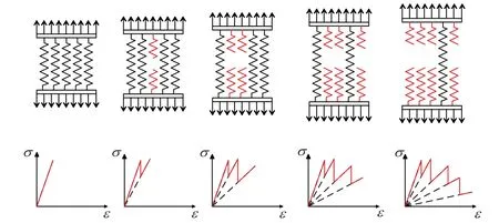
Figure 13:The stochastic fracture model with the spring bundle [115]
At present, the finite element analysis of the low cycle fatigue response of concrete structures can be easily realized.However, the number of cycles of fatigue load acting on a concrete structure sometimes is so large that it would undoubtedly lead to a huge amount of calculation to calculate the fatigue damage accumulation by the cycle-by-cycle integration in the finite element analysis.Therefore, an efficient numerical algorithm is important to realize the simulation for concrete structures under fatigue loading.Some algorithms, such as the cycle jumping algorithm[120–123], the dual temporal scales algorithm [109,124], and the temporal homogenization model[125,126], had been developed to simulate the fatigue process for concrete in a shorter time.Besides, research on various acceleration algorithms is still under exploration, and other algorithms such as the reduced-order modeling algorithm [127] also might attract the attention in the future to be introduced into the accelerated fatigue analysis of concrete.
The great advantage of applying the continuous damage mechanics to studying fatigue constitutive model of concrete is that it accounts for the nonlinear property on the material level without explicitly modeling micro-cracks in advance.The distribution of mechanical degradation in the fatigue process can be depicted by damage variables in the finite element analysis.Since the physical mechanism of concrete damage is not clear, a unified connection has not been established between the evolution of the quasi-static damage and the fatigue damage.To perform the refined analysis of the whole process of structural fatigue in practical engineering, it is required not only a detailed description of the fatigue properties of engineering materials but also the support of appropriate analysis methods and effective calculation techniques.
5 Machine Learning
Machine learning has been utilized to predict the performance of materials or structures in civil engineering [128–136].Due to the high uncertainty, the fatigue loading of concrete is a random process affected by many factors, such as loading period, specimen size, and environment.The deterministic fatigue models may not cover the combined effects of various factors that affect the fatigue resistance of concrete.Machine learning techniques can overcome the inherent limitation in conventional computing models.
Artificial neural networks (ANN), as a machine learning technique, are commonly used to estimate the fatigue life or fatigue strength of concrete, considering the material and dimensional properties of the test specimens and loading conditions.In ANN, there are three layers of neurons,namely input, hidden, and output layers.Each neuron of the hidden layer is connected to the neurons in the subsequent and previous layer by directed synapses with variable weights, as shown in Fig.14.The hidden layer can be regarded as the regression module.The collected test data is input for training, and the prediction data can be output after the regression module.From Eq.(1), there are four quantities to determine theS-Ncurve, the compressive strengthfc, the maximum stressσmax, the minimum stressσmin, and the ultimate loading cyclesNf.In [137], the database has been utilized from the published test literature, and the inputs werefc,σmin, and the ultimate loading cyclesNf.Through training, validation, and testing of the neural network, the maximum fatigue strengthσmaxwas predicted as the output.It shows that the prediction accuracy is higher than theS-Nexpressions recommended in the codes.Other researches have been presented in this field.For example the material properties, dimensions, and loading conditions of components have been considered as inputs, and the fatigue lifeNfas outputs is predicted after training of the neural network [138–142].Moreover, machine learning is also a good option to estimate the fatigue failure reliability of structures [143–145].
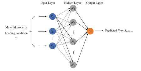
Figure 14:The example of an ANN
Deep learning models have achieved remarkable results in image recognition.It is indicated that deep learning models such as the convolutional neural network (CNN), can be applied in crack detection and localization for concrete structures [146–148].There are many CNN architectures which have been recently applied to crack and damage detection of concrete structures, such as AlexNet [149], ResNet [150], VGG [151], and so on.The general CNN architecture consists of five main layers of the neural network, including input, convolution, pooling, fully connected,and output layers, as shown in Fig.15.The image data is input through the input layers, and the predicted results are stored in the output layers.The main objective of the convolution layers is to extract features in an image input with a convolution operator.The pooling layers are connected behind the convolution layers, and the purpose of introducing them is to simplify the output of the convolution layers.The fully connected layers are to take the output of the previous layer (i.e., the pooling layer) and then apply weights to predict the correct results.Besides, some auxiliary layers, such as dropout and batch normalization (BN) layers, can be added according to the research needs.It can be seen that automatic crack and damage detection with deep learning can help to evaluate the fatigue performance of structures in time in the future,although there are few applications at present.Furthermore, some deep learning models, such as AlexNet, GoogLeNet, ResNet, can also be implemented to mechanical property estimation through analyzing microscopic images in nondestructive testing [152].
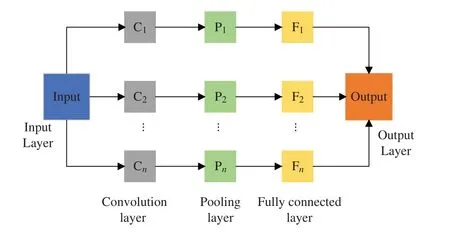
Figure 15:The general CNN architecture
Machine learning is expected to be a tool to interpolate or predict more results based on the limited experimental or finite element computational data without burden such as economy or computational time.At the same time, it is possible to realize the automatic structural performance detection by the crack identification function of deep learning.It can better serve the fatigue design of concrete to combine machine learning methods and conventional computing models.However, there is more work to be done across the field of concrete fatigue.
6 Summary
In this study, the development of fatigue analytical models of concrete is presented and discussed.According to this review, it can be concluded that:
· The research on concrete fatigue mainly includes experimental study, research on the crack growth, analysis of whole process response, and prediction using machine learning.
· The early experimental research results provide a certain basis for engineering life prediction; however, the empirical relationships between fatigue life and stress level obtained by the regression of experimental data obviously could not meet modern engineering needs.
· Based on fracture mechanics research, the fatigue model can limitedly reflect the physical mechanism of single crack growth under fatigue loading.However, it was difficult to describe the effect of several randomly distributed microcracks in concrete under complex stress.
· The damage-based fatigue models for concrete can realize the analysis of the whole process of concrete structures under fatigue loading.It can also be used to study the randomness of fatigue of the concrete structures.
· Machine learning provides a new idea for developing a fatigue prediction model of concrete.
· At present, the exploration of concrete fatigue analysis models and calculation methods which can be applied to practical engineering design faces great challenges, and further studies still need to be performed.
Acknowledgement:The authors wish to express their appreciation to the reviewers for their helpful suggestions, which greatly improved the presentation of this paper.Additionally, the second author wishes to appreciate the support from the Chinese Scholarship Council (CSC) under the Joint(Executive Program between Egypt and China (Program (2019–2023)).
Funding Statement:This work was supported by the National Natural Science Foundation of China (Grant Nos.52078361 and 51678439) and Innovation Program of Shanghai Municipal Education Commission (Grant No.2017-01-07-00-07-E00006).
Conflicts of Interest:The authors declare that they have no conflicts of interest to report regarding the present study.
 Computer Modeling In Engineering&Sciences2023年1期
- Computer Modeling In Engineering&Sciences的其它文章
- A Fixed-Point Iterative Method for Discrete Tomography Reconstruction Based on Intelligent Optimization
- An Integrated Scheduling Algorithm for the Same Equipment Process Sequencing Based on the Root-Subtree Vertical and Horizontal Pre-Scheduling
- A Review of the Current Task Offloading Algorithms,Strategies and Approach in Edge Computing Systems
- Machine Learning Techniques for Intrusion Detection Systems in SDN-Recent Advances,Challenges and Future Directions
- Cooperative Angles-Only Relative Navigation Algorithm for Multi-Spacecraft Formation in Close-Range
- Lightweight Network Ensemble Architecture for Environmental Perception on the Autonomous System