
An Unambiguity and Anti-Range Eclipse Method for PD Radar Using Biphase Coded Signals
2023-01-25 02:53JihongYanWeihanNiJianshuZhaiandHaiyangDong
Jihong Yan,Weihan Ni,Jianshu Zhai and Haiyang Dong
1Yangtze Delta Region Institute(Quzhou),University of Electronic Science and Technology of China,Quzhou,324000,China
2School of Information and Communication Engineering,University of Electronic Science and Technology of China,Chengdu,611731,China
ABSTRACT Target detection is an important research content in the radar field.At present,efforts are being made to optimize the precision of detection information.In this paper,we use the high pulse repetition frequency(HPRF)transmission method and orthogonal biphase coded signals in each pulse to avoid velocity ambiguity and range ambiguity of radar detection.In addition,We also apply Walsh matrix and genetic algorithm (GA) to generate satisfying orthogonal biphase coded signals with low auto-correlation sidelobe peak and cross-correlation peak,which make the results more accurate.In a radar receiver,data rearrangement of echo signals is performed,and then pulse compression and moving target detection(MTD)are utilized to get the final velocity and range information of a target without velocity ambiguity and range ambiguity.Besides,a small transmitting pulse time width is adopted to reduce the working blind area,and two different high pulse repetition frequencies(HPRFs)are adopted to solve the problem of range eclipse.Simulation results finally prove the effectiveness and feasibility of the proposed method.
KEYWORDS Biphase coded;velocity ambiguity;range ambiguity;genetic algorithm;range eclipse
1 Introduction
Digital array radar is a kind of radar whose transmission and reception are operated digitally,which has many incomparable advantages over traditional phased array radar,such as high amplitude,phase control accuracy and beamforming flexibility,large dynamic range,strong reliability,and low loss and sidelobe[1–3].It has played an essential role in radar field.
Pulse doppler(PD)radar is easily realized on a digital array platform and usually used to detect long-range targets.In the search stage,PD radar uses the same antenna to transmit and receive.The advantage by turning on transmission and reception alternatingly is that there will not be any transmission leakage at the receiving end.
When the delay time of target echo is greater than the repetition period of transmitted pulses,range ambiguity will occur[4–6].In addition,when the Doppler frequency caused by target motion is greater than half of the repetition frequency of the transmitted pulse,velocity ambiguity will happen[7].In order to solve this problem,high pulse repetition frequency (HPRF) working mode is often adopted[8,9],but it also brings range ambiguity[10–13].The traditional method of eliminating range ambiguity is using several different pulse repetition intervals(PRIs)based on the remainder theorem[14],the one-dimensional set algorithm [15],the look-up table method [16] and so on.However,all those methods above have their own shortcomings.
The biphase coded signal is a common pulse compression radar signal.It has been widely researched and adopted for non-ultra-high-velocity targets due to its great noise-like and low probability of intercept characteristics[17].In this paper,HPRF working mode is adopted to avoid velocity ambiguity,narrow width of transmitted pulses is applied to reduce the blind zone,and two different HPRFs are used to solve range eclipse.In addition,multiple orthogonal biphase coded signals,based on Walsh matrix and performed genetic algorithm (GA) [18,19],are transmitted within the time corresponding to the maximum range of the radar to mitigate range ambiguity.In radar receiver,data rearrangement is performed on multiple echoes of transmitted pulses,and then pulse compression and moving target detection(MTD)are performed,after which the range ambiguity can be eliminated.
The structure of this paper is as follows:The cause of pulse radar ambiguity is analyzed,and the signal model without blur and eclipse is given in Section 2.The design flow of the transmitting signals used to resolve ambiguity is given in Section 3.The radar signal processing process is presented in Section 4,and in which the data rearrangement method is changed compared with the traditional way.The flexibility of the proposed method through simulation experiments is in Section 5.The conclusion is in Section 6.
2 Signal Model and Problem Description
2.1 Distance and Velocity Ambiguity and the Solution
For pulse radar,when echo delay of a target is longer than pulse repetition interval (PRI),the target echo will not fall in the cycle,and the measured target distance is not the real distance but a distance with range ambiguity.As shown in Fig.1,sm(t)is themth transmitting pulse,rm(t)is the echo of themth transmitting pulse,τ0is the delay of the target echo,and then the transmitting pulse can be expressed as Eq.(1).

wheres(t)is the pulse compression signal(linear frequency modulation signal or phase coded signal),andtPRIis the time corresponding to one PRI.
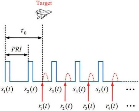
Figure 1:Echo diagram of generating range ambiguity
Pulse radar calculates the distance by measuring the delayτ0of the echor1(t),andτ0is estimated by the peak position after pulse compression which is generally achieved by matched filter doing crosscorrelation operation.Whenτ0is greater than PRI,cross-correlation calculation is performed with the current transmitted pulse signals2(t)usingr1(t),which is as shown in Eq.(2).

The peak position ist=τ0-tPRI,and the delay reflected by the peak is different from the real echo delayτ0,so the distance ambiguity appears.However,if a group of pulse signals with low cross-correlation peak value are transmitted,the peak value will appear only whenr1(t)ands1(t)are cross-correlated,which can effectively solve the distance ambiguity problem.The relative formula is as shown in Eq.(3).

The peak position ist=τ0,from which the distance can be correctly calculated.
2.2 Range Eclipse and the Solution
Radar adopts the transceiver switching mode,which inevitably results in range occlusion,that is,the echo delay of the targett1=PRI.At this time,the echo of the target happens to be at the moment of pulse transmission,and the echo diagram is shown in Fig.2.
Traditional HPRF radar mainly realizes anti-occlusion by using varying PRFs.Therefore,three different PRFs are adopted in order to have no ambiguity and no occlusion in the traditional method.But only two different PRFs are needed to realize detection without ambiguity and occlusion if the transmitted signal with low cross-correlation peak value is adopted to solve the ambiguity.

Figure 2:Echo diagram of generating range occlusion
3 Design of Transmission Signal
As can be seen from the above section,distance ambiguity can be solved by transmitting multiple signals with low cross-correlation peak values at time division.This section will take two-phase coded signals as an example to illustrate the design process of transmitting signals.
In order to obtain the obvious main lobe after pulse compression,not only the peak value of cross-correlation between signals but also the peak value of auto-correlation side lobe of each signal is reduced during signal design.For two-phase coded signal set,theith signal can be expressed as Eq.(4).

whereφi,jis thejth element’s phase of theith signal,and

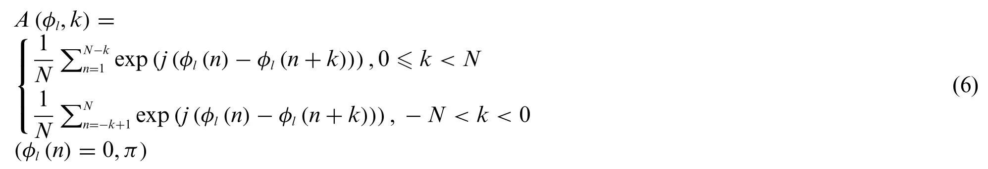
is the pulse with the width ofTzandKis the length of the encoded signal.The auto-correlation function of signals is as Eq.(6).
The cross-correlation function of two signals is as Eq.(7).
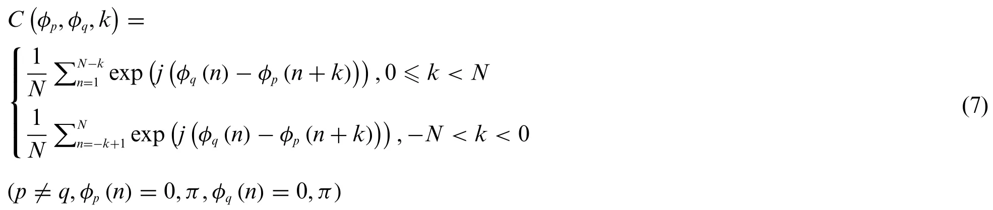
φm(n)represents thenth element’s phase of themth signal[20].
As Section 1 says,transmitting signal set is optimized by GA.The steps are as follows:
Construct the fitness function of GA as Eq.(8).
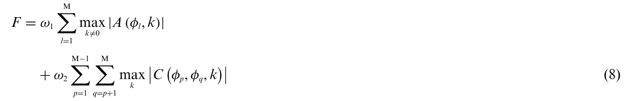
The fitness function is to calculate the auto-correlation sidelobe peak and cross-correlation peak of signals.Theω1andω2are weighting coefficients,satisfyingω1+ω2=1.
Generate anN×Nwalsh matrix and make random exchange,then take the fitness function value shown in the minimization formula as the criterion and select M waveforms from the matrix.The selectedM×Nmatrix is as the input of GA.
Use GA to optimize theM×Nmatrix.The flow chart is shown in Fig.3 and the specific steps are as follows:
a) Calculate the fitness function value of the matrix,judge whether it meets the end condition,that is,whether the number of iterations reach the upper limit,or successive differences of optimum fitness between adjacent two generations are less than the threshold.If so,stop the iteration,otherwise,carry out the next selection,crossover,mutation,and recalculate the fitness function values until the end condition is met.
b) Discard the individual with the largest fitness function value and select the remaining individuals with the smaller values in the population for later crossover and mutation.
c) Pair individuals in the population randomly and cross the biphase coded values of paired individuals randomly to recombine into new ones.
d) According to the mutation probability,the code values,also the biphase coded values,of some columns in the random mutation population get mutation from 1 to-1 or from-1 to 1.
e) Replace the individuals with the largest fitness function value in the original population with those that have the smallest fitness function value in the new population,then return to Step a for the next iteration.
Figure 3:Flow chart of genetic algorithm
4 Process of Radar Signal
4.1 Process of Transmission
In order to avoid velocity ambiguity,HPRF mode is adopted in this paper.Multiple pulses,composed of the two-phase coded signal set designed in Section 3,which have low auto-correlation sidelobe and cross-correlation peak value,are transmit within the time corresponding to the maximum detection range of radar,which can effectively solve the distance ambiguity.The design process of emission parameters is as follows:
First,the time duration of pulseτis determined according to the radar range blind areaRbas Eq.(9).

wherecis the velocity of light.Meanwhile,the maximum radar periodTmaxis determined according to the farthest detection rangeRmaxof the radar as Eq.(10).

Then,the PRI is determined according to the maximum radial velocityvmaxof the target as Eq.(11).

wherefdmaxis the maximum Doppler frequency caused by maximum radial velocityvmax.The numbermof transmitted pulses in an unambiguous periodTmaxis determined as Eq.(12).

Then,select a group of signals produced by the above method to transmit in an periodTmax.As shown in Fig.4,in one periodTmax,transmitmorthogonal signalsa1,a2,...,am,which have great auto-correlation and cross-correlation performance.The radar system usually needs to accumulate to obtain a better detection on targets,so several periodsTmaxform a coherent processing interval(CPI).The number ofTmaxin a specific CPI can be selected according to actual scenarios.
Figure 4:Schematic diagram of transmitted signal
4.2 Process of Receiver
4.2.1 Data Reshaping
This paper focuses on transceiver switching radar system.Therefore,the receiver cannot receive signals during transmission time,so the echo data sequenceR1collected in the first period is shown as Eq.(13).

where 0an(n=1,2,...,m)signifies that the receiver is shut off during transmitting the pulsesan(n=1,2,...,m),andranis the receive data when the radar switches to receiving mode after transmitting.All of the above received data is digital signals that have been down-converted to baseband.
The echo data matrixRis shown in Eq.(14),which is composed by rearranging the echo data of a CPI.
The schematic diagram of the matrixRarrangement method is shown in Fig.5.Each row is corresponding to an unambiguous periodTmax.The beginning time of the first row is the time when the pulse signala1starts to be transmitted,and the second row is corresponding to the time when the pulse signala2starts to be transmitted,and so on for subsequent rows.
Figure 5:Data rearrangement diagram
4.2.2 Pulse Compression
Perform matched filtering on each row of the echo data matrixRto implement pulse compression processing.The first rowR1inRis performed matched filtering withA1constructed by adding 0,that is to makeA1andRare the time series with same length,after the transmitted signala1.Use the frequency domain pulse compression processing method as Eq.(15).

where FFT is fast Fourier transform and IFFT is inverse fast Fourier transform.A1[-n]is the reverse of the sequenceA1and[ ]*is conjugate operation.The second rowRis matched withR2,and then perform the same process for the remaining rows.In the end,put the processed data into corresponding rows in a new matrixX.
4.2.3 Moving Target Detection
FFT is performed on each column in the new matrixXgotten after pulse compression,that is MTD processing,to achieve coherent accumulation,and the peak value calculated finally in this new matrix reflects the range and velocity information of the target.
5 Simulation Analysis
Assuming that a certain scene requires the radar’s range blind areaRb<500 m,the maximum detectable range isRmax= 100 km,and the maximum detectable speed isvmax= 2000 m/s.Then in order to meet the demand of range blind areaRb,and according to the calculation formula of transmitting parameters in radar signal process,the transmitting pulse width is at most as Eq.(16).

If the radar’s radio frequency isfRF= 300 MHz,then the wavelength isλ= c/f= 1 m,and the pulse repetition interval is met Eq.(17).

According toRmaxthe radar periodTmaxis at least as Eq.(18).

From the above requirements,the radar transmitting parameters are set as Eq.(19).

SoRbis as Eq.(20).

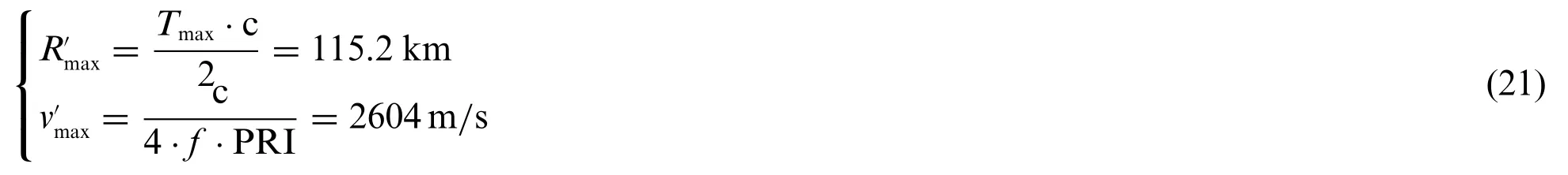
The maximum unambiguity distance and velocity,according to such way in this paper,are respectively as Eq.(21).
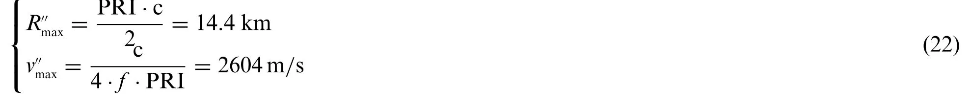
By contrast,the outcome of traditional PD radar is as Eq.(22).
Obviously,the traditional PD radar cannot meet the requirement ofRmaxin this scenario except for increasing PRI as Eq.(23).

Then we get the values as Eq.(24).
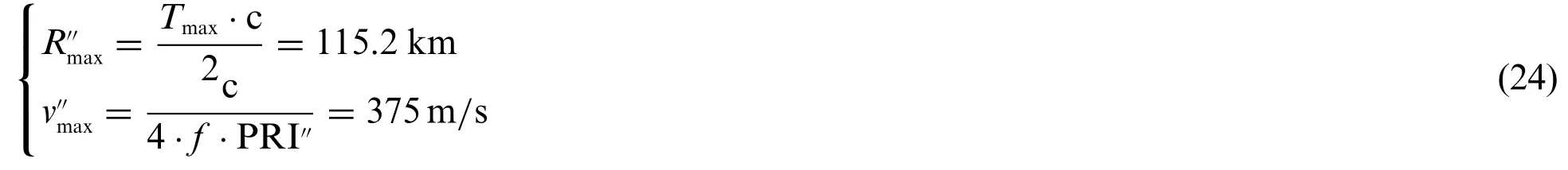
The requirement ofvmaxcannot be met at this time,so the traditional PD radar cannot complete detection in this scenario,but the method proposed in this paper can deal with this problem.The simulation results of the traditional radar and of the proposed method are given below to verify the feasibility and superiority of such way by comparison.
5.1 Simulation Analysis of Transmitting Signal Designed by GA
In the simulation of transmitting waveform design using genetic algorithm,the length of biphase code is set to 256.Moreover,at least 8 waveforms need to be designed according to Eq.(19).Therefore,16 transmitting waveforms are designed in this paper for using (M = 16,N = 256).The two coefficients in the fitness function are set asω1= 0.5,ω2= 0.5,the maximum genetic iteration is set as 1500 and the maximum stagnation iteration is set as 200.The convergence of the fitness value of GA is shown in Fig.6,in which the fitness value converges to 9.564 from the 611th to 811th generation.
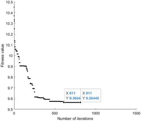
Figure 6:Convergence graph of fitness value
The auto-correlation function of the signal obtained at the end of iteration is shown in Fig.7a,and the cross-correlation function is shown in Fig.7b.It can be seen that the signal has low autocorrelation sidelobe and low cross-correlation peak value.
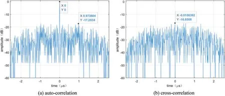
Figure 7:Auto-correlation and cross-correlation
5.2 Simulation Results 1
Assume that there is only one target,the distance is 20 km,and the speed is 530 m/s.Then the echo diagram is shown in Fig.8,in which the echo delay of the targett1>PRI,that is,the target distance is beyond the maximum unambiguity range of traditional radar,but it is within the maximum of the proposed method in this paper.
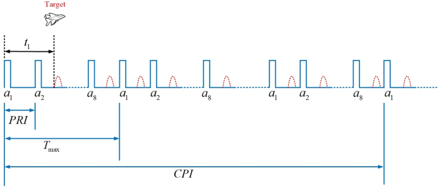
Figure 8:Schematic diagram of the echoes of one target
The signal to noise ratio(SNR)is set to-20 dB in the simulation,and the transmission parameters are set as Eq.(19).The maximum unblurred distance and maximum unblurred speed of traditional PD radar are shown in Eq.(22).Traditional PD radar only adopts a two-phase coded transmitting waveform,and its moving target detection diagram(MTD diagram)is shown in Fig.9a,in which the calculated distance is inconsistent with the set distance and it is just equal to the difference between real distance and the maximum unfuzzy range,so it is difficult for traditional radar to distinguish whether the target is within the maximum unambiguity range,generating ambiguity.But with the method in this paper with Eq.(21),and select eight signals,having low auto-correlation sidelobe and cross-correlation peak,as transmitting set from waveforms designed in Section 5.1,and the MTD figure is shown in Fig.9b,in which range ambiguity does not exist.
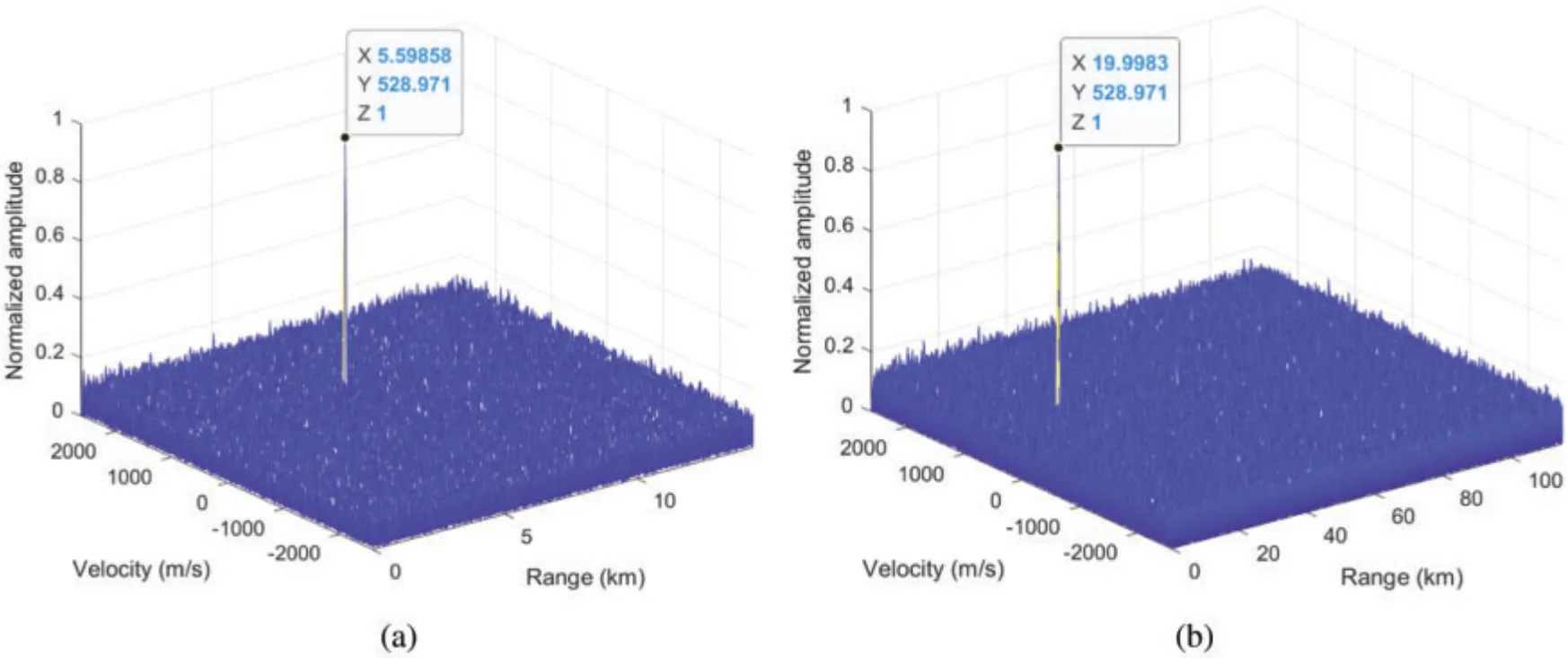
Figure 9:MTD diagram comparison of single target
5.3 Simulation Results 2
Assume that there are two targets,the distance of the first is 10 km and the second is 24.4 km,and the speed of the first is 240 m/s and the second is 240 m/s too.The echo delay difference between these two targets is one PRI,which means overlap happens as shown in Fig.10,in which the dashed red line is the echo from target 1,and the solid green line is the echo from target 2.
In the same way,the signal to noise ratio(SNR)is set to-20 dB,and the transmission parameters are set as Eq.(19).As shown in Fig.11a,in which only one peak value in the figure,that is,the traditional PD radar cannot distinguish the number of the real targets,which is because the speed of the two targets is the same,and the distance difference is just equal to the maximum unblurred distance so that the peak value of the two targets in the MTD figure is at the same position.But with the method in this paper,the real targets can be found as shown in Fig.11b,in which the two targets are detected without ambiguity.
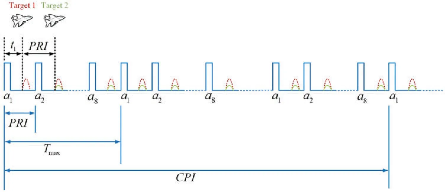
Figure 10:Schematic diagram of overlapping echoes of two targets
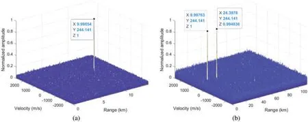
Figure 11:MTD diagram comparison of two targets
5.4 Simulation Results 3
Assume that the target’s distance is 14.4 km and the speed is 120 m/s,and set the echo delayt1= PRI.If the radar adopts transceiver switch mode,range occlusion will be generated as shown in Fig.12.In order to solve such problem,we can switch PRF in oneTmaxlike in Fig.12,usingb1,b2,b3,···.
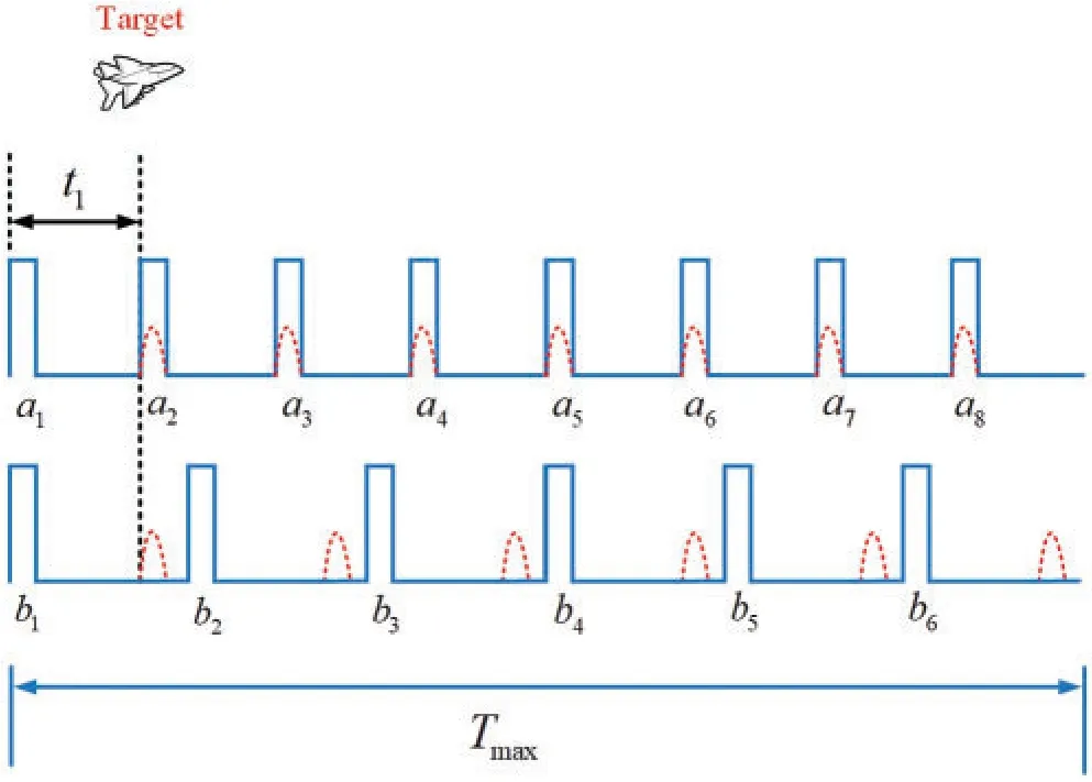
Figure 12:Scheme of echoes with range eclipse
The SNR is still set to-20 dB.If there are 8 transmitting pulses in oneTmax,as shown in Fig.13a,the target cannot be detected.But if there are 6 pulses oneTmax,as shown in Fig.13b,the target can be found.
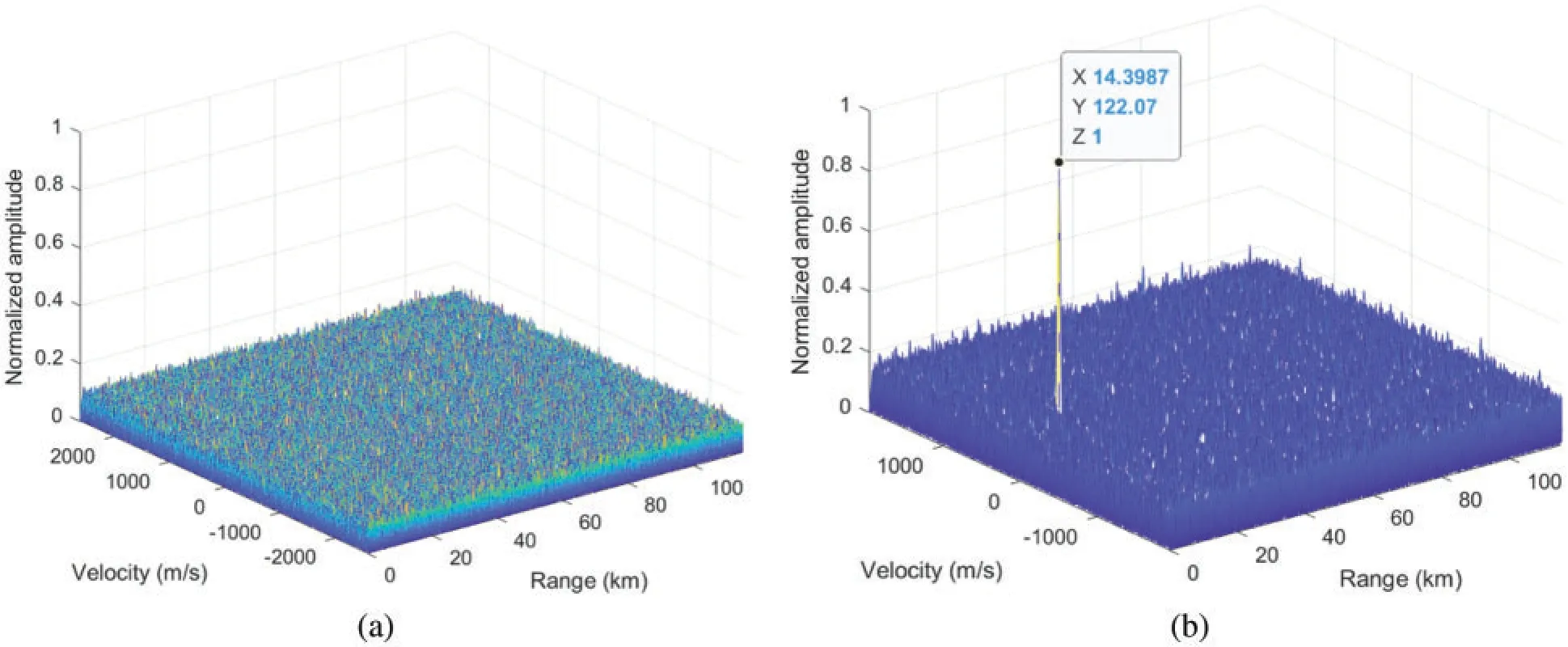
Figure 13:MTD diagram comparison with range eclipse
6 Conclusion
Range ambiguity and velocity ambiguity of traditional PD radar cannot be eliminated at the same time,which means increasing maximum unambiguous range also reduces maximum unambiguous velocity.Meanwhile,range eclipse is also a problem.The HPRF orthogonal signal transmission mode and signal processing scheme in this paper make PD Radar implement long-range unambiguous detection without velocity ambiguity and realize anti-range eclipse.Simulation results prove the feasibility of this scheme.In future work,we will consider adopting the simultaneous transceiver mode and reasonably suppressing the transmission leakage to achieve our purpose discussed in this paper more effectively.
Acknowledgement:Our deepest gratitude goes to the reviewers and editors for their careful work and thoughtful suggestions that have helped improve this paper substantially.
Funding Statement:This paper is supported by the Special Science Foundation of Quzhou(2020D007,2021D009).
Conflicts of Interest:The authors declare that they have no conflicts of interest to report regarding the present study.
 Computer Modeling In Engineering&Sciences2023年2期
- Computer Modeling In Engineering&Sciences的其它文章
- Monitoring Study of Long-Term Land Subsidence during Subway Operation in High-Density Urban Areas Based on DInSAR-GPS-GIS Technology and Numerical Simulation
- Slope Collapse Detection Method Based on Deep Learning Technology
- An Extended Fuzzy-DEMATEL System for Factor Analyses on Social Capital Selection in the Renovation of Old Residential Communities
- Failure Mode and Effects Analysis Based on Z-Numbers and the Graded Mean Integration Representation
- Static Analysis of Anisotropic Doubly-Curved Shell Subjected to Concentrated Loads Employing Higher Order Layer-Wise Theories
- An Effective Machine-Learning Based Feature Extraction/Recognition Model for Fetal Heart Defect Detection from 2D Ultrasonic Imageries