
Evolution of polarization singularities accompanied by avoided crossing in plasmonic system
2023-02-20 13:14YiXiaoPeng彭一啸QianJuSong宋前举PengHu胡鹏DaJianCui崔大健HongXiang向红andDeZhuanHan韩德专
Chinese Physics B 2023年1期
Yi-Xiao Peng(彭一啸), Qian-Ju Song(宋前举), Peng Hu(胡鹏),Da-Jian Cui(崔大健), Hong Xiang(向红),‡, and De-Zhuan Han(韩德专),§
1Chongqing University,Chongqing 400044,China
2School of Science,Southwest University of Science and Technology,Mianyang 621010,China
3Chongqing Key Laboratory of Core Optoelectronic Devices for Quantum Communication,Chongqing Optoelectronics Research Institute,Chongqing 400060,China
Keywords: polarization singularities,topological charge,avoided crossing,inversion symmetry
1. Introduction
Polarization manipulation plays an important role in modern electromagnetic applications. For a periodic system such as photonic crystal slabs (PCSs), polarization of the far-field radiation can be characterized topologically in the momentum space. As the typical singularities of polarization, vortex polarization points(V points)and circular polarization points(C points) have attracted much attention.[1,2]The V points are vortex centers in the polarization directions of far-field radiation and the radiation intensity vanishes at the V point. The V points are closely related to the interesting phenomena of bound states in the continuum (BICs). In electromagnetics,the BIC is a special type of spatially localized eigenmode lies in the band of continuum while no radiation happens.[3–10]In PCSs the BICs can be realized when both the upward and downward radiations correspond to a V point since no radiation occurs. The unique properties of BICs have aroused much interest for the potential applications in lasing,[11,12]sensing,[13]and antennas.[14]The C points are points of circular polarization and surrounded by elliptical polarization states. As the orientation of the polarization ellipse is undefined,C points are regarded as polarization singularities.
The polarization states of the radiation from PCSs are highly dependent on the symmetry of system. For the PCSs with in-plane inversion(C2)and up-down mirror(σz)symmetries the BICs can be readily observed. When the symmetry of the system is broken,the new polarization phenomena will be brought forth.[2,15–24]For example, breaking the in-plane C2symmetry will eliminate the original BICs but induce C points.With other polarization states accompanied,full coverage on the Poincare sphere can be realized.[17]Breaking the inplane C6symmetry for at-ΓBICs with high-order topological charge can generate off-ΓBICs from the at-ΓBIC and create or annihilate C points pairwise.[2]Breaking the in-plane inversion symmetry enables metasurfaces to support sharp high-Qresonances arising from a distortion of symmetry-protected BICs.[15]The BICs withQfactor beyond typical inversesquare law are achieved by breaking the symmetry in an C4vstructure.[16]
Breaking the up-down mirror symmetry can also bring new features to the far-field radiation. Unidirectionally guided resonances (or unidirectional BICs) that only radiate to one side of the structure are realized in PCSs with slanted wall[21]or with asymmetric substrate.[19]The broken mirrorflip symmetry in up-down direction can be used to enhance TE–TM coupling and give rise to BIC with unique spatial characteristics.[16]Chiral quasi-BICs can be realized by introducing chiral perturbation to break the up-down mirror symmetry.[24]
The C2symmetry and the up-down mirror symmetry can be broken simultaneously in a system with lateral inversion symmetry. Recently,Zenget al. investigated the evolution of polarization singularities in a PCS with lateral inversion symmetry, proposing a flexible mechanism to generate and tune C points.[25]A similar structure has also been proposed to realize the perfect single-sided radiation and absorption without mirrors.[26]In the reported researches,the evolution of the singularities happens in an isolated band and only a small range of geometry variation is involved.
Here we report a complete evolution process of the polarization singularities accompanied by avoided crossing in a plasmonic system which is composed of a thin metallic film sandwiched by two dielectric gratings. When the system has up-down mirror symmetry, the band crossing happens and a symmetry-protected BIC is supported in the antisymmetric mode band. When the gratings on two sides take a relative shift along the periodic direction, the up-down mirror symmetry will be broken and the avoided band crossing happens.In this process,the original symmetry-protected BIC(V point)splits into two C points;meanwhile,other C point pairs appear in a certain single band, or emerge in both two bands simultaneously due to the avoided crossing. With the continuous tuning of the misalignment,C point pairs can merge into BICs or annihilate,andvice versa. The topological charges are conserved in the whole process. With the relative shift between the two grating varying from 0 to half the period, a complete involution process is traced. In the end,the asymmetry of radiation of the system is briefly discussed.
2. Overview of system
The system under study,illustrated in Figs.1(a)and 1(b),has a thin metallic film sandwiched between two identical one-dimensional dielectric gratings. The system is periodic in thexdirection and uniform in theydirection. The main parameters are the periodaof the system, the thicknesstmof the metal film, the widthwand the thicknesstdof the dielectric ridges of the grating, and the relative shiftsbetween the gratings on the two sides. Specifically, herea=600 nm,tm=40 nm,td=100 nm, andw=300 nm. The permittivity of the metal film is described by the Drude-type model:ε(ω)=1-ω2p/(ω2+iγω),whereωpis the plasma frequency andγis the collision frequency. As we focus on the radiation loss of a resonant mode,the intrinsic loss of the nanoparticles is ignored,that is,γ=0,and the plasma frequency is set to beωp=1.37×10¹⁶rad/s. The refractive index of the dielectric layer and the background are set to bend=1.515 andnb=1,respectively.
The band structure of the system along thexdirection,which has been studied before,[27]is shown in Fig.1(c). In the figure the error bars represent the imaginary parts of the resonance frequencies, the black dots indicate the position where the error bar decreases to infinitesimal, and a BIC appears since the quality factor diverges here. When the relative shift between the two dielectric gratingss=0,the structure has updown mirror symmetry and in-plane C2symmetry simultaneously.The modes in A band and B band are orthogonal to each other,with A band corresponding to the odd mode and B band the even mode. Owing to the orthogonality,the two dispersion curves cross straightly through each other. Furthermore, for the mode in A band at theΓpoint, the profile(Hy)along thexdirection is odd, which is symmetrically incompatible with the external radiation,hence a symmetry-protected BIC[4]appears here, as indicated by the black dot shown in the first panel in Fig. 1(c). Whens/=0 ora/2, both the in-plane C2symmetry and up-down mirror symmetry of the structure are broken. As a result, the symmetry protected BIC atΓpoint disappears. Meanwhile,avoided band crossing happens and a band gap appears due to the coupling between the two originally orthogonal modes. Whensincreases to 0.2432a,an accidental BIC appears atkx=0.054 in the upper band. This BIC will vanish again when the relative shift further increases.Whensincreases toa/2, the structure possesses in-plane C2symmetry again. As a result, the avoided band crossing disappears and a symmetric protected BIC forms in the A band at theΓpoint. Note that the structure with shiftsis mirror symmetric(σx)with that ofa–s,then the band diagram corresponding tosfors >0.5acan be obtained by that ofa–sby symmetry.
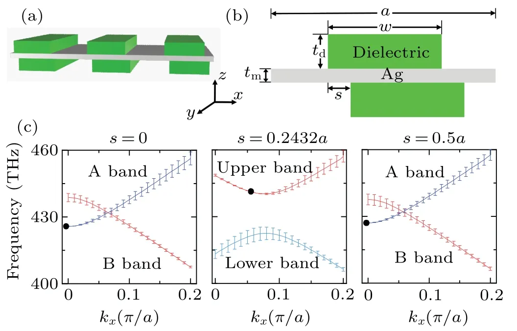
Fig.1. (a)Schematic diagram of plasmonic system consisting of a metallic film sandwiched between two identical dielectric gratings with relative shift,(b)x–z plane view of the structure,(c)band diagrams of the structure under different shifts, with error bars denoting the imaginary parts of resonance frequencies and the black dots representing the corresponding zeros.
3. Formation of off-Γ BIC
To find how the off-ΓBIC forms and vanishes,the topology for the polarization state of the radiation in the momentum space is examined. For a given band of a periodic slab, the polarization of the far-field radiation varies with the in-plane Bloch wave vectork||. In the zero-order diffraction zone, the far-field radiating plane wave has the samek||as that of the Bloch mode, hence the polarization vectord(k||) in thes–pplane of the radiation can be projected onto the structure plane and mapped onto the Brillouin zone,with the projected vector written asd′(k‖)=(k‖)+(k‖).[2,3]For a fully polarized light, the polarization state can be completely described by the ellipticity angleχ, with tanχbeing the ratio of the polarization ellipse’s minor to major axis, and the orientation angleθthe angle between the long axis of the polarization ellipse and thexaxis.[28]
The topology of the radiation polarization in the momentum space can be presented by the distribution ofd′(k‖). The topological charge carried by the polarization singularity is defined as[3]
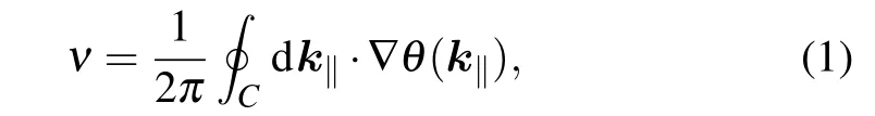
whereCis a closed path enclosing the polarization singular point in counterclockwise direction,νdescribes the number of times the major axis of the polarization ellipse orbits the ringC. If pathCencloses a V point,chargeνis an integer;if pathCencloses a C point,νis a half-integer.
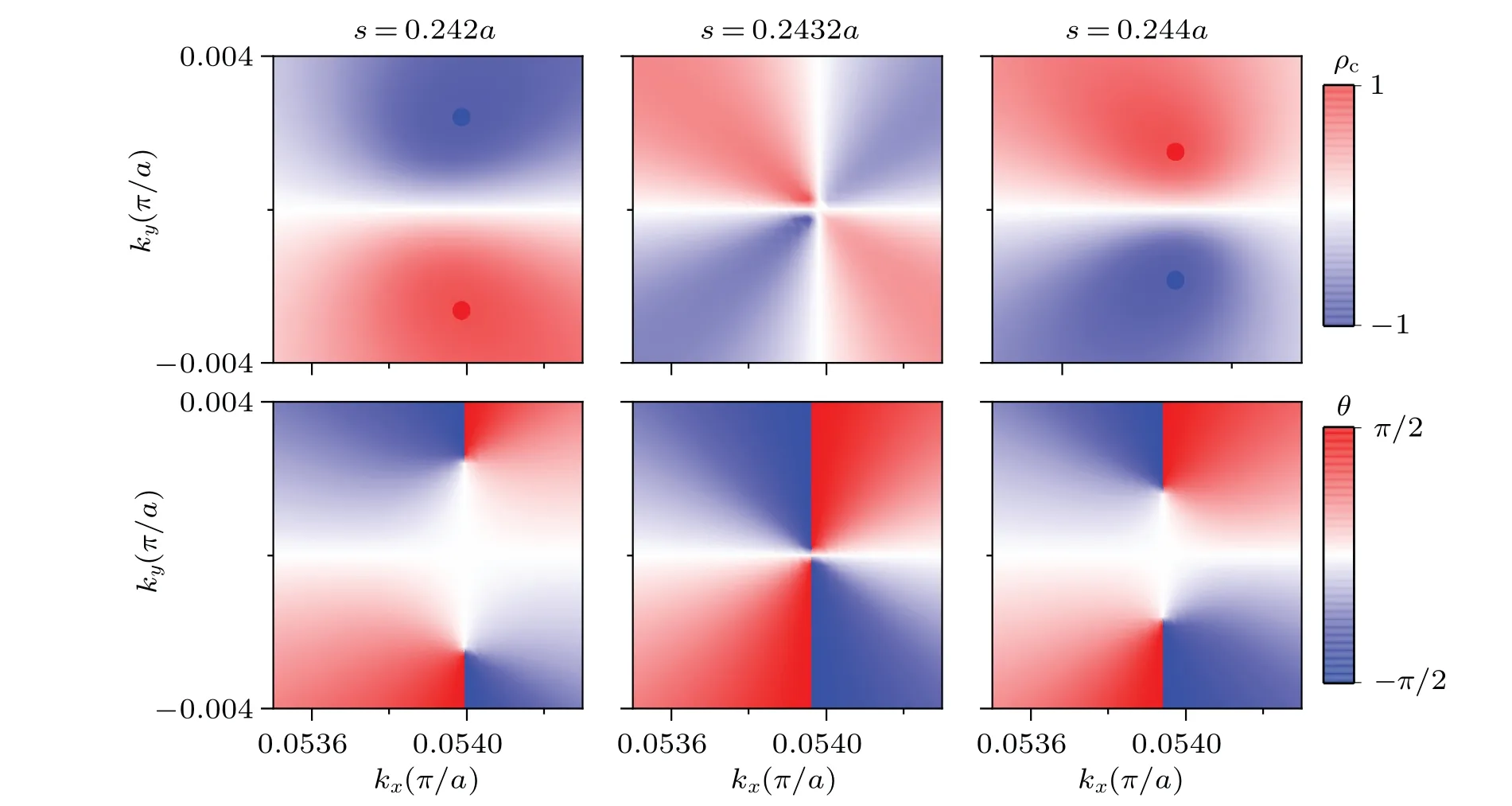
Fig.2. Evolutions of polarization states near s=0.2432a,with upper panels and lower panels showing the distributions of ellipticity and orientation angle of the polarization ellipses,respectively.
Figure 2 shows the distributions of the orientation angleθand ellipticityρcof polarization states in the downward radiation for the system with different shifts at the vicinity ofs=0.2432a. Here the ellipticity is defined asρc=sin(2χ).Whens=0.242a,the ellipticity diagram shows that there are two points withρc=+1 and-1,which correspond to a right circularly polarized state and left circularly polarized state,respectively. Theθdiagram indicates that at each point, the orientation angleθmakes aπradiance change in the counterclockwise direction. So the topological charges carried by the two C points are both +1/2. With the increase ofs, the two C points move toward each other and merge into a V point whensreaches 0.2432a. As shown in the middle panel of Fig.2,two L lines(a line along which the polarization is linear) with orthogonal polarization cross at this point, andθmakes a 2πchange around this point, hence a V point with charge of+1 is formed. With the further increase ofs,the V point splits into two C points again as shown in the right panel of Fig. 3. Note that the handedness of the upper and lower C points for the case ofs=0.244aare opposite to those for the case ofs=0.242a. This process can be regarded as that two C points with the same topological charge move toward each other and merge into a V point,then depart away. In this process the topological charges are conserved. The upward radiation field exhibits a similar behavior,and the corresponding V point forms at the same point whens=0.2432a,hence a BIC forms here.
4. Global evolution of polarization singularities
To further trace the whole evolution of these singularities in the momentum space with respect to the parameters, the projected polarization states in the downward direction withsvarying from 0 toa/2 are calculated,and the results are shown in Fig. 3. Here the polarization states are represented by the corresponding ellipses. Note that when|ky|is larger than 0.9,the band diagram extends outside the light cone and the corresponding states are evanescent.
Whens=0,due to the up-down mirror symmetry and the in-plane inversion symmetry of the structure, there is a symmetry protected BIC at theΓpoint in A band, as mentioned above.
When the two dielectric gratings slightly shift,the mirror symmetry is broken and avoided crossing happens. The symmetry protected BIC splits into two C points, marked as C1and C2in the lower band. Whensincreases to 0.02a, other two pairs of C points(C3and C4,C5and C6)appear. The pair in the lower band(C3and C4)carries-1/2 charges while the pair in the upper band (C5and C6) has +1/2 charges. With the further increase ofs, the two C points (C5and C6) in the upper band move around the right side,while the two pairs of C points in the lower band(C1and C3,C2and C4)will collide in pair and annihilate whensreaches 0.07a. Whensincreases to 0.14a, other 4 C points (C7and C9, C8and C10) emerge in pairs. The C points in each pair have the same handedness while opposite charges. With the further increase ofs,C9and C10move outwards and eventually go out of the light cone whensreaches 0.18a,becoming regular bound states. Meanwhile,C7and C8,C5and C6,move toward each other. Whensapproaches to 0.2432a, they merge into two BICs located symmetrically on thekxaxis with charges of+1. With further increase ofs, the two BICs break into two pairs of C points again. Whensexceeds about 0.28a, two C points,and,will move into the light cone from outside. However,the handedness is different from that of C9and C10. With further increase ofs, C8and, C7andwill collide and annihilate whensapproaches to 0.40a,and C5and C6will move outwards. Whensincreases to about 0.41a,two pairs of C points(and,and,) appear in the lower band. Whensexceeds 0.48a, the 4 C points (andin the lower band,C5and C6in the upper band) vanish simultaneously. When s approaches to 0.5a, the voided crossing disappears, andandmerge into a BIC.
As mentioned before, the structure with shiftsis mirror symmetric (σx) with that ofa–s, then the polarization vectord′(k‖) corresponding tosis also mirror symmetric with that fora–s. Hence the polarization topology for structure withs >a/2 can be obtained from that ofa–s. It worth noting that the radiations on the two sides of the structure are different since the up-down mirror symmetry is broken. However,d′(k‖) in upward radiation can be obtained by inversing that in downward radiation due to the lateral inversion symmetry of the system.[25]
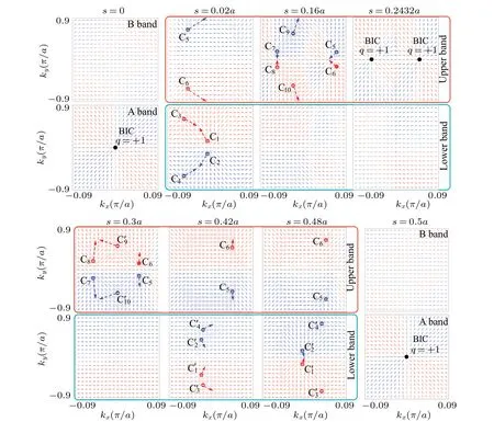
Fig.3. Evolutions of polarization singularities with geometry variation,with ellipses(dots)in red and blue corresponding to the right-handed and left-handed elliptical (circular) polarizations, respectively, symbols “+” and “-” denoting the sign of the topological charges for C points, and arrows indicating the direction of motion for C points with the increase of s.
From Fig. 3, it can be seen that the C points can be categorized into three types according to their generation mechanisms. One is those generated from the V points(BICs)due to the breaking of the in-plane C2symmetry, like C1and C2.The two C points carry the same quantity of charge but opposite handedness,which is reported in other researches.[1,17]The second type, like C7and C9, C8and C10, are generated from originally 0-charged polarization states. At the beginning,the paired two C points are very close to each other,and have the same handedness but opposite charges. Such C point pairs have also been reported in Zeng’s work.[25]The third type, like C3, C4, C5, and C6(or,, C5, and C6), which appear or vanish simultaneously,is different from the first two types. If the two C points in the same band are regarded as a pair,they are far apart from each other,opposite to the first two types in which they two C points are located closely when they first appear. If the two C points in different bands but similar in-plane positions are regarded as a pair,like C3and C5(or C4and C6),both the charge and handedness are different,which is also different from the first two types in which either the charge or the handedness is identical with each other.
The generation of the third type of C points is related to the avoided band crossing. Figure 4(a) shows the band diagram fors=0, where the two bands cross each other. Figures 4(b) and 4(c) are the projected polarization states of the upper band and lower band of the system withs=0.02a, respectively. The black lines are the projected intersection lines of A band and B band in Fig.4(a). It can be seen that the two C point pairs are both located at the vicinity of the intersection line. From Fig.3 it can be seen that the radiation field of the A band and the B band are both nearly linearly polarized. Moreover, at the vicinity where C3, C4, C5, and C6appear whens=0.02a, the polarizations in bands A and B are nearly perpendicular to each other. These phenomena suggest that the formation of the C points can be understood as the superposition between the polarization states in A band and B band.When avoided crossing happens, the states in A band and B band will mix to form a new band structure. At the vicinity of the crossing,the new formed states can be expressed as[29]

with “+” and “-” corresponding to one of the new formed states, andφis a phase angle dependent on the system parameters. At certain locationsφAandφBhave nearly orthogonal polarizations and equal amplitudes, and ifφapproaches to ±π/2 for a certains(for example,s=0.02ain our system),circular polarization states will form there. According to Eq. (2), if one state is left circularly polarized, the other one must be right circularly polarized. This explains why C3and C5(C4and C6)have opposite handedness. On the other hand,the conservation of topological charge requires C3and C5(C4and C6) to carry opposite charges since the total charge is 0 at the vicinity of C3and C5at the beginning. Meanwhile,the mirror symmetry in theydirection(σy)guarantees that C3and C4(C5and C6) have opposite handedness and same charges.Similarly, the generation of,, C5, and C6whensdecreases from 0.5ato 0.48a, as shown in Figs. 4(d)–4(f), can also be explained in this way.

Fig.4. Generation of C points due to avoided band crossing. (a)and(d)Band diagrams with band crossing at s=0 and s=0.5a,respectively. ((b),(c)and(e),(f))Projected polarization states of upper and lower bands of the system with s=0.02a and s=0.48a,respectively. The black lines are the projected intersection lines of A band and B band shown in panels(a)and(d).
5. Discussion
In the end,we make a comparison between the plasmonic system here and the reported dielectric system with same symmetry. According to the reported results,[25,26]the dielectric system exhibits high up-down asymmetry in radiation. However, for the plasmonic system here, the ratio of theQfactor for the upward radiation to downward radiation is less than 8 according to our calculation, which is far less than the reported results. The low asymmetric ratio comes from the low light transmission of the metal film in our system. According to previous work,[25]the bound of the asymmetric ratiof2(the ratio of the upward radiation power to the downward radiation power)is given by(1-t)/(1+t)≤f2≤(1+t/(1-t),wheretis the direct transmission through the structure (the Fabry–Perot background). For the dielectric slab, the full transmission(t=1)can be reached and thus extremely high asymmetric ratio can be realized. While for the plasmonic system here,the full transmission cannot be attained and high asymmetric ratio is not exhibited either.Another difference is that accidental BICs at off-Γpoints are supported in the plasmonic system while in the dielectric system only the at-ΓBIC is supported.Off-ΓBICs are propagating states without loss and can be applied to on-chip beam guiding[30]and directional vector beam generation.[31]
6. Conclusion and perspectives
In conclusion,we have studied the evolution of the polarization singularities in a periodic plasmonic system with lateral inversion symmetry. In the evolution,BICs can split into C point pairs and conversely, C points can merge into BICs.Meanwhile, two C points with opposite charges can also collide and annihilate. C points are generated in three ways in this system. In addition to the known mechanism reported in other researches, avoided band crossing can also induce C point pairs. The whole process is governed by the law of charge conservation. Unlike the reported dielectric system in which only at-ΓBIC is supported, off-ΓBICs are observed in our plasmonic system. This work proposes a new scheme for generating the polarization singularities and may find its applications in polarization manipulation.
Acknowledgements
Project supported by the National Natural Science Foundation of China (Grant Nos. 12074049 and 12047564),the Fundamental Research Funds for the Central Universities, China(Grant Nos. 2020CDJQY-Z006 and 2020CDJQYZ003), and the Research Foundation of SWUST (Grant No.21zx7141).

- Chinese Physics B的其它文章
- The coupled deep neural networks for coupling of the Stokes and Darcy–Forchheimer problems
- Anomalous diffusion in branched elliptical structure
- Inhibitory effect induced by fractional Gaussian noise in neuronal system
- Enhancement of electron–positron pairs in combined potential wells with linear chirp frequency
- Enhancement of charging performance of quantum battery via quantum coherence of bath
- Improving the teleportation of quantum Fisher information under non-Markovian environment