
Explicit Topology Optimization Design of Stiffened Plate Structures Based on the Moving Morphable Component(MMC)Method
2023-02-26 10:16XudongJiangChangLiuShaohuiZhangWeishengZhangZongliangDuXiaoyuZhangHuizhongZengandXuGuo
Xudong Jiang,Chang Liu,2,⋆,Shaohui Zhang,Weisheng Zhang,2,Zongliang Du,2,Xiaoyu Zhang,Huizhong Zeng and Xu Guo,2,⋆
1Department of Engineering Mechanics,State Key Laboratory of Structural Analysis for Industrial Equipment,International Research Center for Computational Mechanics,Dalian University of Technology,Dalian,116023,China
2Ningbo Institute of Dalian University of Technology,Ningbo,315016,China
3Beijing Institute of SpacecraftSystem Engineering,Beijing,100094,China
ABSTRACT This paper proposes an explicit method for topology optimization of stiffened plate structures.The present work is devoted to simultaneously optimizing stiffeners’shape,size and layout by seeking the optimal geometry parameters of a series of moving morphable components(MMC).The stiffeners with straight skeletons and the stiffeners with curved skeletons are considered to enhance the modeling and optimization capability of the current approach.All the stiffeners are represented under the Lagrangian-description framework in a fully explicit way,and the adaptive ground structure method,as well as dynamically updated plate/shell elements,is used to obtain optimized designs with more accurate analysis results.Compared with existing works,the proposed approach provides an explicit description of the structure.Thus,a stiffened plate structure with clear stiffener distribution and smooth geometric boundary can be obtained.Several numerical examples provided,including straight and curved stiffeners,hierarchical stiffeners,and a stiffened plate with a cutout,validate the effectiveness and applicability of the proposed approach.
KEYWORDS Topology optimization; stiffened plate structures; moving morphable component (MMC); straight/curved skeletons
1 Introduction
Plate structures have played an essential role in aerospace,automotive,marine and civil engineering due to their high load-bearing efficiency,lightweight construction and other excellent traits[1,2].These structures,however,are susceptible to deformation,strength,vibration and buckling under use since their thicknesses are much smaller compared to their other dimensions.To improve the load bearing capacity of plate structures,in the past few decades,many methods have been developed to analyze and enhance their strength,stiffness,stability,dynamic performance[3–6],etc.,among which the use of stiffener is one of the most efficient and cost-effective methods.This accordingly arouses great interest of researchers in the investigations of optimal design of stiffened plate structures.
As an advanced design methodology,structural optimization [7–13],including size,shape and topology optimization,is widely used to solve material distribution problems of stiffened plate structures.For example,Lagaros et al.[14] investigated the optimization design of stiffened shell structures with straight stiffening beams by using evolutionary algorithms.In[15–18],a set of thickness parameters or spacing parameters are chosen as design variables to optimize the size and shape of stiffeners,while the topological form of the stiffeners remains constant during the optimization process.Pavlovčič et al.[19,20]studied the shear strength of the steel plate with trapezoidal stiffeners from numerical and experimental aspects.Kapania et al.[21] studied the optimization results of curvilinear stiffened panels.They found that curvilinear stiffeners may lead to lighter-weight designs than straight stiffeners for certain design cases.After that,Mulani et al.[22,23] proposed a new framework to design curvilinear stiffened panels considering complex,multifunctional and aircraft structural concepts.Wang et al.[24] and Hao et al.[25] developed a novel bilevel optimization strategy based on the hybrid model to optimize the size and layout of stiffened panels with reinforced cutouts.Liu et al.[26,27] suggested a non-parametric shape optimization method for designing the stiffeners on shell structures,in which the stiffness and eigenvalue maximization problems are considered.Moreover,Wang et al.[28,29]introduced an interesting bio-inspired approach for stiffener optimization,where the optimized shape and location of non-uniform curved grid stiffeners can be found in an adaptively evolutionary way.Besides size and shape optimization applied to the stiffener design of plate structures,topology optimization,which can provide more design space and flexibility,is also extensively carried out to optimize stiffened plate structures.Lam et al.[30] suggested an automated optimization method for determining the location of stiffeners from a variable thickness plate iteratively.By introducing a second-ranked microstructure,Ansola et al.[31]introduced a secondranked microstructure in the stiffened optimization framework and simultaneously optimized the shell’s geometry and the stiffener layout.Afonso et al.[32] developed an integrated computational tool to find the optimal material distribution of variable thickness plates and free form shells,in which topology optimization is performed using both a hybrid algorithm and a homogenization approach.Similarly,Ma et al.[33]established a generative design method based on the homogenization method and an equivalent model to optimize stiffened plates.Sigmund and his co-authors [34]successfully applied the SIMP method combined with a novel computational morphogenesis tool to full-scale aircraft wing design,where the intricate details that appeared spontaneously in the optimization process(e.g.,curved spars and local plate structures)could be observed clearly.Recently,Zhang et al.[35]proposed a novel B-spline-based method for structural topology optimization.Based on this framework,Feng et al.[36]effectively utilized B-spline control parameters to characterize the stiffener distribution reinforcing the plate/shell structures.Some other latest investigations conducted on the stiffener optimization of plate structures can be referred to[37–42].
Most of the stiffened structure optimization approaches mentioned above are based on classical implicit solution frameworks that the optimized stiffeners are identified from a black-and-white pixel image,which cannot guarantee that the optimized results are clear stiffeners rather than block-like patterns.Furthermore,the implicit bitmap-like geometric representation may result in a large number of design variables and ambiguous stiffener boundaries.In order to address these problems,some new design methods for stiffened structures based on bionic inspirations and growth simulation have been developed.Mattheck et al.[43]proposed a novel technique based on the swelling function of a commercial finite-element code.Ding et al.[44]developed a growing and branching tree model to generate stiffener layout patterns inspired by natural branching systems.Ji et al.[45]employed a bionic growth approach,which combines a bionic branch model and optimization criteria,to optimize the stiffener layout of the plate/shell structures.Li et al.[46–48] proposed a novel explicit approach to perform topology optimization of stiffened structures via a biologically inspired algorithm and then used it to discover the optimal internal cooling geometries in the heat conduction system.Dong et al.[49]used an adaptive growth method to improve the buckling resistance performance of plate/shell structures by optimizing the stiffener pattern.Unlike implicit topology optimization approaches,these natural growth-based algorithms can obtain explicit stiffener layouts rather than block-like material distributions,making the optimized results more conducive to practical applications.Nevertheless,most of these methods employ smear-out technology/equivalent stiffness technology for structural response analysis,which is difficult to accurately predict the local mechanical behavior (e.g.,local buckling and local stress)of stiffened plate structures.Furthermore,some of these methods are based on pre-defined criteria and lack rigorous sensitivity analysis.
To summarize,although numerous approaches have been proposed to optimize stiffened plate structures,there is still some room for further improvement.In the present work,a more effective and practical approach is developed under the moving morphable components (MMC)-based solution framework[50]to solve the problem of explicit topology optimization of stiffened plate structures.In this method,each stiffener is regarded as a structural component with explicit geometric parameters,and the optimal stiffened structure can be obtained by optimizing the shape,size,and layout of these components.Both straight and curved stiffeners are considered in this paper to enhance the geometry modeling and optimization capability.In the present work,the Lagrangian description combined with the adaptive ground structure and dynamically updated plate/shell elements is used for the optimization process,which makes the proposed method capable of obtaining more accurate analysis results and clear stiffened structures.Thanks to the explicit geometric description,the optimized stiffener structure can be directly imported into the CAD/CAE system without resorting to additional post-processing processes.Furthermore,the feature sizes of the stiffeners can also be easily controlled.
The remainder of this paper is organized as follows.The topology optimization model of stiffened plate structures based on the MMC method is introduced in Section 2.Then,problem formulation and sensitivity analysis are provided in Section 3.In Section 4,some typical examples are studied to illustrate the effectiveness of the proposed approach.Finally,the main concluding remarks are given in the last section of the paper.
2 Topology Optimization Model of Stiffened Plate Structures Based on the MMC Method
2.1 Geometry Description of Stiffened Plate Structures
With the aim of doing topology optimization explicitly and geometrically,the MMC-based solution framework was first proposed by Guo et al.[50].In the MMC method,some moving morphable components are adopted as the basic structural building blocks for topology optimization,and each component is allowed to move,deform,merge and overlap in the design domain freely.The explicit parameters that describe each component’s geometry and position are used as the topology design variables.In the MMC-based framework,the topology description of structural components can be constructed in both Lagrangian[51]and Eulerian description-based frameworks[52].In order to achieve high accuracy numerical analysis at relatively low computational efforts,in the present work,both the optimization model and analysis model of stiffened plate structures are described in a pure Lagrangian way.The Lagrangian description can be seamlessly integrated with the adaptive ground structure and adaptive re-meshing technology,which provides a natural advantage for using body-fitted FE meshes to simulate the stiffened plate structures.Detailed aspects will be reported in the following.
For a typical stiffened plate structure shown in Fig.1,the stiffeners and the base plate can be regarded as being made up of a set of stiffener components and a plate component,where the stiffeners perfectly adhere to the base plate.Based on the Lagrangian description way,the profile of each component can be explicitly determined by its geometric parameters.Here we consider the stiffeners with a straight skeleton and a curved skeleton,respectively.Note that both types of components are of constant thickness in the present work.For a cuboid stiffener component(see Fig.2)defined by the thicknesst,the heighthand a straight skeletonare the two endpoints),the coordinates of any point on the skeletonCsand the mid-surfaceS0of the component can be expressed as
and
whereμ∈[0,1]represents a coefficient of convex combination andη∈[0,1]denotes the introduced arc-length coordinate in the height direction.
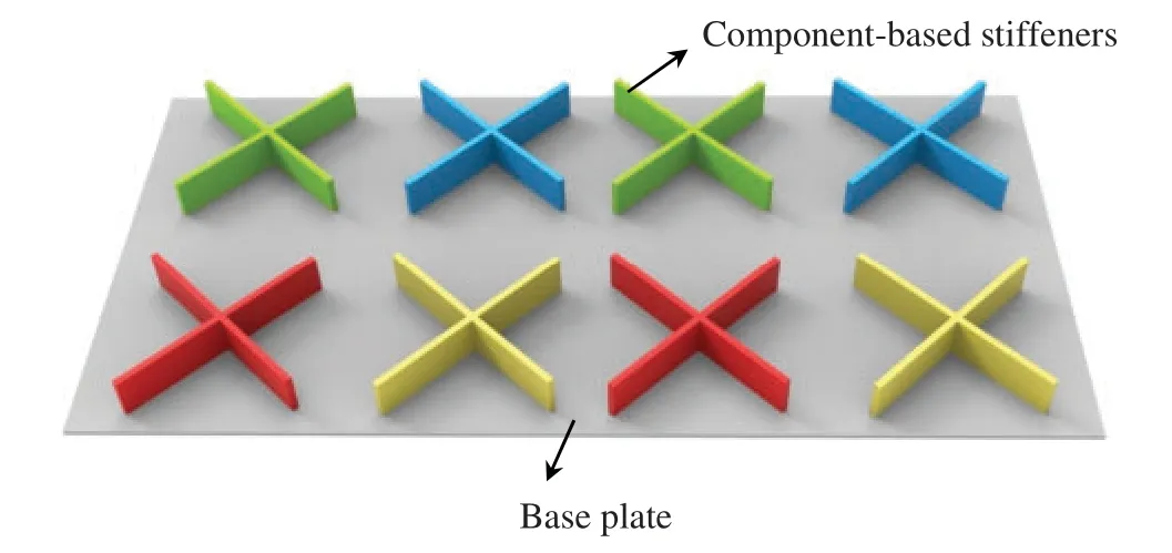
Figure 1:A typical stiffened plate structure constructed by some structural components
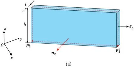
Figure 2: (Continued)
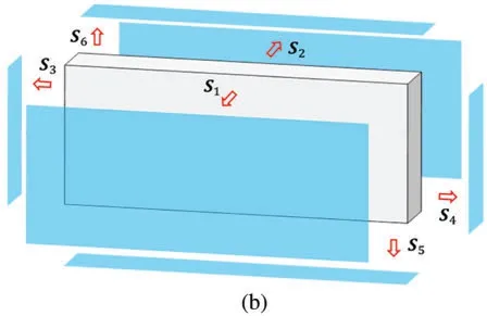
Figure 2:The geometry description of a stiffener component with the straight skeleton:(a)Geometric model of the straight stiffener(b)The outer boundaries of the straight stiffener
For a curved component with constant thickness as shown in Fig.3,we can use a quadratic Bezier equation to define the coordinates of an arbitrary point on the curved skeletonCcand mid-surfaceS0as
Based on Eqs.(2)and(4),the profile of the outer boundaries of a component-based stiffener can be described in the following way:
wherens(μ)denotes outward normal vector of the skeleton andr∈[0,1]is an introduced parameter to characterize the position along the thickness direction.
Figure 3:The geometry description of a stiffener component with the curved skeleton:(a)Geometric model of the curved stiffener(b)The outer boundaries of the curved stiffener
In the MMC-based topology optimization approach,although the boundary of a single thinwalled component is smooth,the boundary of the region occupied by multiple overlapped components may not be smooth any more.This issue can be alleviated in the Eulerian description and fixed 2D/3D FE mesh-based MMC approach by introducing the so-called ersatz material model [52],where the equivalent stiffness of an element is determined by the values of the global topology description function on its four nodes.In the present work,since Lagrangian description is used for representing the geometry of a component as well as the layout of the structure,it is quite important to avoid the intersection of components during the process of optimization.Besides,the intersection or overlap of these stiffeners is also generally to be avoided in the design process of stiffened plate structures.In the present work,to prevent the stiffeners from intersecting with each other during the optimization process,the component-connection mechanism based on a so-called adaptive ground structure method is employed[53].As illustrated in Fig.4,a ground structure is composed of the base plate and component-based stiffeners,where the stiffeners are connected to each other by a series of driven nodes and the entire structure is updated iteratively by moving a series of driven nodes and varying some size parameters of the components.Correspondingly,the optimal shape and size of the stiffeners can be obtained by optimizing the coordinates of these movable nodes and other control points of the skeletonsas well as the size parameters of the components(GC=(t,h)).Furthermore,by removing those narrow components with very small thickness after completing the optimization process (since these components have little effect on the overall performance of the stiffened structure),the topology changes of the structure are achieved and the final optimized stiffened plate structure can be obtained.
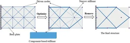
Figure 4:A schematic illustration of the node-driven adaptive ground structure method
2.2 Minimum Thickness Control of Stiffeners
In practical applications,constraining feature sizes of the structural members is very meaningful to improving the design manufacturability[54].This,fortunately,can be easily achieved in the explicit optimization framework by directly setting bound limits on relevant geometry parameters.In the present work,benefiting from the explicit geometric description of the stiffeners,it is also easy to control the sizes of stiffeners,such as the heighthand the lengthfor a straight stiffener anddufor a curved stiffener).However,for the thickness control of stiffeners,the lower boundtlcannot be directly imposed on the thickness of a component due to the operation of removing the narrow components.To be specific,if the lower boundtlon the thickness is imposed,the topology change of the stiffened plate structure cannot be realized by removing the components with thicknesses less than a thresholdtr(usuallytr≪tl)from the final optimization result(note that there are many stiffeners whose thickness values are betweentrandtl).To address this problem,we introduce a penalization mechanism to prevent the value of the thickness from falling into the interval [tr,tl]during the process of optimization.By penalizing the stiffener thickness with a middle value (i.e.,t∈[tr,tl]),the values of the thickness in the optimized results are either less than the thresholdtror great than the lower boundtl.Then the final structural topology change can be obtained by removing the stiffeners with thickness less than the thresholdtr,while the minimum thickness constraint can also be satisfied.
In the present work,for a stiffener optimization problem with feature size constraintt∈[tl,tu],we use the following expression to realize the penalization:
whereH=H(x−tl) is a translated Heaviside function,and its regularized versionH∊(x−tl) in common practice can be expressed as
where∊denotes a parameter that controls the magnitude of regularization andαis a small positive number introduced to set the thresholdtrin the penalization scheme and we takeα=tr/(tl−∊)in the present work.It should be noted that instead oft,the value oftpis utilized to treat as the thickness of each component in numerical implementation.As can be seen in Fig.5,by using the Heaviside penalty function,only the thicknesstpof the components witht∈[tl−∊,tl+∊] will fall into the interval[tr,tl+∊]during the process of optimization.Accordingly,the number of components withtp∈[tr,tl+∊]can be further reduced by setting∊to a small positive number(in the present work,we take∊=0.1)and the minimum thickness control can be effectively achieved.
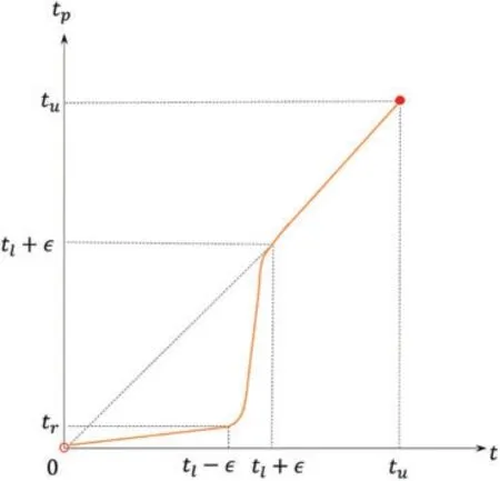
Figure 5:The stiffener thickness penalization by the Heaviside function
2.3 Numerical Analysis Model of Stiffened Plate Structures Based on the MMC Method
In the present work,classical stress/displacement shell elements with three or four nodes constructed from a refined shell theory[55]are adopted for structural response analysis.As the geometry of the stiffened plate is described explicitly in a pure Lagrangian way,a clean and clear geometry model with smooth boundaries can be generated; therefore,it is quite convenient to discretize both the base plate and the stiffeners into an adaptive body-fitted mesh through the adaptive re-meshing technique(see Fig.6 for reference).Compared with the 3D solid or equivalent stiffness model with a fixed finite element(FE)mesh commonly used in previous works,the shell-element-based numerical analysis model adopted in the present work has a relatively low computational cost and is undoubtedly more suitable for the simulation of stiffened plate structures.Furthermore,since the FE model is built on exact geometry and a refined local FE mesh can be constructed in the regions of special interest(e.g.,along the boundary of inner holes and the interfaces between the stiffeners and the base plate,see Fig.28a for reference),more accurate analysis results can be obtained at each iteration step of optimization.
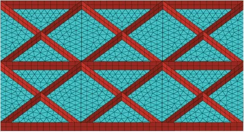
Figure 6:A schematic illustration of the numerical analysis model of a stiffened plate structure
3 Problem Formulation and Sensitivity Analysis
3.1 Problem Formulation
Based on the above discussions,it can be concluded that the design variables of a stiffened plate structure topology optimization problem in the proposed MMC-based framework can be summarized asD=(DN,DC).HereDN=denotes the integrated vector composed of the coordinates of all driven nodes/control points,withrepresenting the coordinates of thei-th driven node/control point andnndenoting the total number of driven nodes/control points.The symbolDC=is the geometric parameters of all stiffener components,withGj C=(tj,hj) being the geometric parameters vector ofj-th stiffener andncdenoting the total number of stiffeners.In the present work,it is assumed that the height of all stiffeners remains constant throughout the process,so the vectorGj Ccan be reduced toGCj=tj,j=1,...,nc.
With the above result bearing in mind,the optimal design problem for stiffened plate structures can be formulated as
whereIis the objective function,gi,i=1,...,nare constraint functions andUDis the admissible set that the design variable vectorDbelongs to.
In the present study,with the purpose of enhancing the global stiffness of the stiffened plate structures,the considered optimization problem is to minimize the structural compliance under the available volume constraint and the corresponding problem formulation can be formulated as
wherefandurepresent the nodal force vector and the nodal displacement vector,respectively.The symbolKdenotes the global stiffness matrix assembled from element stiffness matrix of the base plate and the stiffeners.is the upper bound of available solid material.gj,j=1,...,ngdenote some other inequality constraints(e.g.,feature size constraints),wherengis the total number of these constraints.In addition,represents prescribed displacement on the Dirichlet boundaryΓu.
3.2 Sensitivity Analysis
The proposed solution framework is essentially based on the explicit boundary evolution,and therefore shape sensitivity analysis approach can be performed to obtain the sensitivities of an objective or constraint functional for numerical optimization.According to[56,57],the shape sensitivity of a general objective/constraint functional can be written as a volume integral
whereuandwrepresent the primary and adjoint displacement fields,respectively.∂Ω=∂Ωidenotes the boundary of all stiffeners and the symbol∂Ωi,i=1,...,ncis the boundary of theith component.is the normal velocity field along δΩi.In the present work,since the considered objective function is the structural compliance,it yields thatu=wandf(u,w)=−Eijklui,juk,l.WhenIrepresents the volume of the stiffened plate structure,we havef(u,w)=1.As can be seen from Eq.(10),the key point for shape sensitivity analysis is to derive the relationship betweenand the variation ofD.
Actually,for a typical component shown in Figs.2 and 3,only the contributions of outer boundaryS1andS2to sensitivities are considered since the areas of other boundaries are too small to be ignored in sensitivity analysis.Therefore,the shape sensitivity of thei-th component can be calculated as
In Eq.(11),the outward normal velocity fieldVkn,k=1,2 associated with the variation of the stiffener boundarySkcan be written as
whereδSkis the variation of the boundarySkandnkdenotes the outward normal vector ofSk.Based on the above results,we next carry out the shape sensitivity analysis of the straight component and the curved component,respectively.
3.2.1 Sensitivity Analysis of the Straight Component
For a typical cuboid component with a straight skeleton as shown in Fig.2,taking the boundaryS1as an example,we have
and
whereS0is the mid-surface of the component and the variation of it can be expressed as follows:
Accordingly,the normal velocity field alongS1can be written as
In Eq.(16),the normal outward vectornscan be easily obtained from the tangential vectorτsof the skeleton,andτscan be calculated in the following form:
Therefore,we have
Based on the above results,the normal velocity field alongS1can be described as follows:
Similarly,the normal velocity field alongS2can be written as
Based on the above equations,the variation ofIwith respect to thei-th component can be expressed as
where the expressions ofAs,Bs,Cs,DsandEscan be found in Appendix A.Summarizing the contributions of all components,the sensitivity of the structural compliance/volume with respect to the design variablesp1sx,p1sy,p2sx,p2syandtofi-th component can be written as
wheresp1andsp2are the total number of the straight components driven by the nodesP1SandP2S.
3.2.2 Sensitivity Analysis of the Curved Component
For a curved component as shown in Fig.3,the variation of the mid-surfaceS0can be deduced easily from Eq.(4)
The tangential vectorτsof the curved skeleton can be calculated as
Accordingly,we have
Based on the above equations,it yields that the normal velocity field alongS1of the curved component can be expressed as
Similarly,Vn2alongS2can be calculated as
Finally,we have
where the expressions ofAc,Bc,Cc,Dc,Ec,FcandGccan be found in Appendix A.In Eq.(26),cp1andcp2denote the total number of the curved components driven by the nodesP1candP3c,respectively.It is worth noting that all the above computations can be performed by surface integrals on the boundary of the components.
4 Numerical Examples
In this section,four numerical examples,including straight and curved stiffeners,hierarchical stiffeners,and a stiffened plate with a cutout,are tested to validate the effectiveness of the proposed approach.Without loss of generality,all involved quantities are assumed to be dimensionless.The Young’s modulus of the base plate and the stiffeners are set asEp=1 andEs=2,respectively,and Poisson’s ratios of both materials areν=0.3.The method of moving asymptotes(MMA)[58]is utilized to solve the optimization problems numerically.The terminating condition of the optimization process is set to the relative changes of the values of the objective and volume functions in two successive iteration steps are less than 0.1%while the volume constraint is satisfied.For all examples,the stiffeners with thickness values less than a threshold oftr=0.05 are deleted from the final optimization results.
4.1 A Plate Example with Straight Stiffeners
In the first example,the optimization problem of a stiffened plate structure with straight stiffeners is tested.The corresponding problem setting is shown in Fig.7.The height of all stiffeners is set ashs=5 and the thickness of the base plate istp=1.As stated previously,the coordinates of the driven nodes as well as the thickness of all stiffener components are taken as design variables.The variation range of the stiffeners’thickness is set tot∈[0.001,2]and the upper bound of the available volume of the stiffeners is=0.1|D|(|D|=200×100×5).As illustrated in Fig.8,three different initial designs consisting of 315,450 and 609 components are adopted in this example to test the dependence of the optimization results on the initial layouts of components.The corresponding numbers of design variables of the three initial designs are 513,736 and 999,respectively.
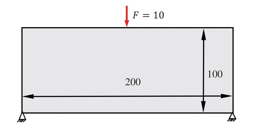
Figure 7:The problem setting of the plate example with straight stiffeners
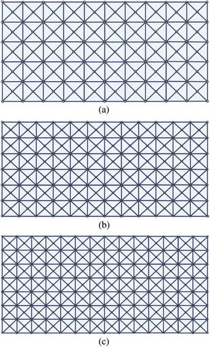
Figure 8:Three different initial designs of the plate example with straight stiffeners:(a)315 components(b)450 components(c)609 components
The corresponding optimized results obtained from the different initial layouts with compliance values of 305.40,303.84 and 303.06,respectively,are displayed in Fig.9 (note that those narrow components with a thickness less than the thresholdtrhave been removed).The figure shows that stiffeners are smoothly distributed and perfectly adhered to the base panel.Meanwhile,clear and clean load transmission paths can be easily extracted from the optimized results without any extra post-processing due to the explicit geometry description.Noticing that although the optimized results obtained from different initial layouts are slightly different,the main load transmission paths assembled by the stiffeners are very similar.Fig.10 depicts the strain energy distributions of all optimized designs;it can be observed that the stiffeners are mainly distributed in the regions with high strain energy,which is reasonable from a mechanics point of view.Fig.11 shows the iteration histories of the compliance value and the volume constraint for the three cases;the structural compliance value decreases rapidly in the first 100 steps and converges by about 300 steps.

Figure 9: The optimized results of the plate example with straight stiffeners obtained from different initial designs:(a)I=305.40(315 components)(b)I=303.84(450 components)(c)I=303.06(609 components)
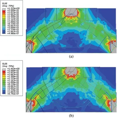
Figure 10: (Continued)
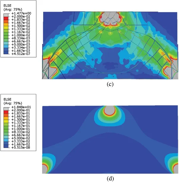
Figure 10:The strain energy distributions of the plate example with straight stiffeners:(a)Optimized design(315 components)(b)Optimized design(450 components)(c)Optimized design(609 components)(d)Base panel
Next,to examine the validity of the proposed penalization mechanism in addressing minimum thickness control of stiffeners,the lower boundtl=1 of the thickness control is imposed in this example (the initial design is the same as Fig.8a).The optimized result with the Heaviside penalization scheme is shown in Fig.12,and the corresponding value of compliance is 311.98.It can be seen from the figure that,compared to the optimized structure (shown in Fig.9a) obtained without a penalization scheme,some local narrow stiffeners disappear in the final optimized structure of imposing the Heaviside penalization scheme.Table 1 lists the thickness values of the optimized stiffeners with the Heaviside penalization scheme(only the data of half of the optimized structure is provided since the structural symmetry).It can be found that,by applying the penalization scheme,all the stiffeners satisfy the prescribed thickness size constraint (i.e.,t∈[1,2]).Compared with the optimized structure in Fig.9a,the compliance value of the structure with the thickness control is higher.This is because imposing the thickness control on the stiffeners during the optimization process inevitably reduces the optimization design space.Although there are certain differences in the stiffener layout of the optimized results,the main force transmission paths for both results are similar.Based on the above comparison,it is concluded that the penalization scheme by the Heaviside function can effectively control the thickness of the stiffeners.Besides the size control of thickness,the proposed method also has the capability of performing other feature size control of the stiffened plate structures,such as the length control and the angle control.This,however,will not be reported in the present work for conciseness.
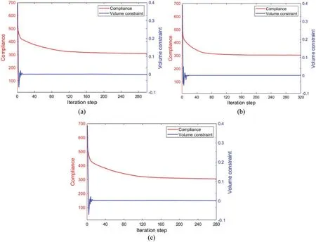
Figure 11: Iteration histories of the objective and constraint values of the three cases of the plate example with straight stiffeners:(a)315 components(b)450 components(c)609 components
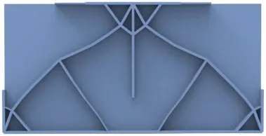
Figure 12: The optimized result with the stiffener thickness penalization mechanism of the plate example with straight stiffeners(I=311.98)
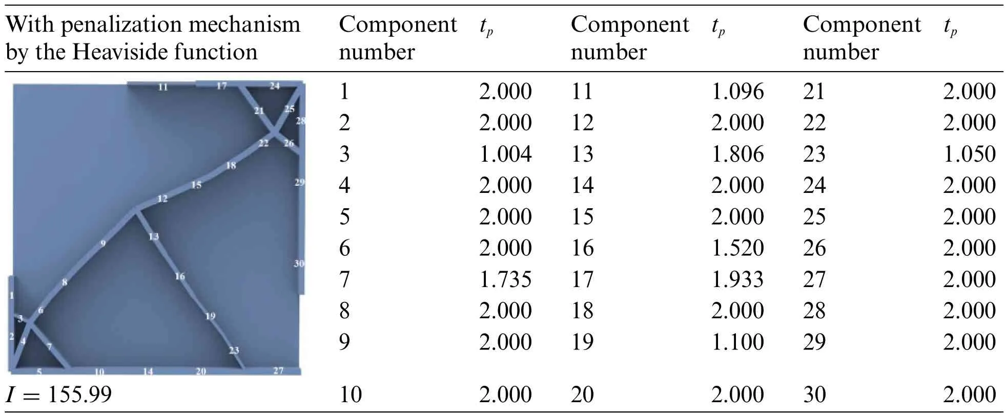
Table 1:The thickness of the stiffeners in the optimized structure with stiffener thickness penalization mechanism of the plate example with straight stiffeners
4.2 A Plate Example with Curved Stiffeners
In this example,the curved stiffener optimization problem is considered.The problem setting of this example is shown in Fig.13.The thickness of the base panel istp=1 and the height of all the curved stiffeners is uniformly set tohs=5.Fig.14 illustrates the initial design of this example.The geometry of each component is determined by three control points of its skeleton and the thickness.Accordingly,the coordinates of these control points/driven nodes and the thickness are taken as the optimization design variables and the total number of design variables is 190.The thickness of all components is only allowed to vary in the range of [0.001,3] and all control points are restricted to move within the design domain framed by the base panel.The upper bound of available material for the stiffeners is=0.16|D|(|D|=150×50×5).
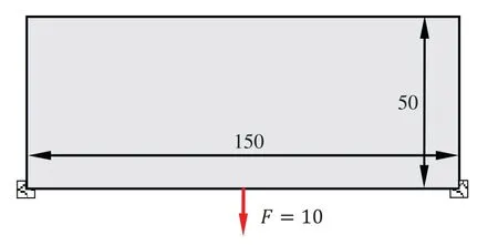
Figure 13:The problem setting of the plate example with curved stiffeners
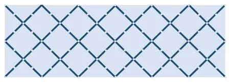
Figure 14:The initial design of the plate example with curved stiffeners
Fig.15 depicts the final optimized result and the corresponding iteration history for the optimization process is shown in Fig.16.As can be seen from the optimized result,some curved stiffeners appear in the optimized structure and form several strong structural members to transfer the point load.Some intermediate designs in the optimization process are presented in Fig.17,which shows the shape and size evolutions of curved stiffeners during the optimization iterations.In the proposed optimization framework,since the profile of the curved stiffeners is described explicitly through a series of geometry parameters,the optimized design can be directly imported into CAD systems,as shown in Fig.18.
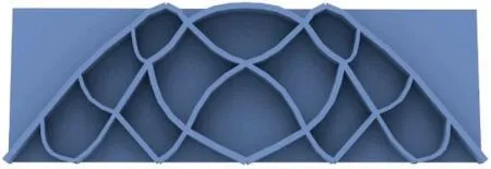
Figure 15:The optimized result of the plate example with curved stiffeners(I=569.05)
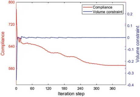
Figure 16: Iteration history of the objective and constraint values of the plate example with curved stiffeners
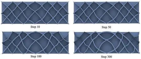
Figure 17:Some intermediate designs of the plate example with curved stiffeners

Figure 18:The CAD model of the optimized structure of the plate example with curved stiffeners
4.3 A Hierarchical Stiffened Plate Example
Hierarchical stiffened configuration,as an advanced design form,is widely used in large industrial equipment.In this subsection,we try to apply the proposed method to the optimization design of a hierarchical stiffened structure.The problem setting of the considered hierarchical stiffened plate example is shown in Fig.19.The thickness of the base plate istp=1 and the height of primary stiffeners and secondary stiffeners arehs1=4 andhs2=2,respectively.The maximum available volume of the stiffeners is=0.125|D|(|D|=100×50×4).Fig.20 shows the initial design with 76 primary components and 128 secondary components and the total number of design variables is 330.During the optimization process,the varying thickness ranges of the primary components and the secondary components are set to[0.001,1]and[0.2,0.5],respectively.
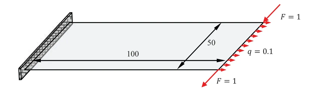
Figure 19:The problem setting of the hierarchical stiffened plate example
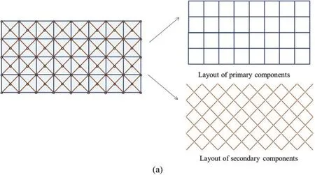
Figure 20: (Continued)
Figure 20:The initial design of the hierarchical stiffened plate example:(a)A top view(b)An overall view
The final optimized hierarchical stiffened plate with a compliance value of 123.14 is shown in Fig.21.As can be seen from the figure,several main force transmission paths composed of the primary stiffeners are generated to effectively resist the in-plane bending moment and tensile forces.Meanwhile,the cross-distributed secondary stiffeners in the plate can well resist shear deformation.In addition,by arranging the primary stiffeners and secondary stiffeners,both the global and local stiffness of the plate structure can be enhanced greatly from a mechanical point of view.Fig.22 shows the iteration history for the optimization process of this example and the corresponding CAD model of the optimized structure is shown in Fig.23.
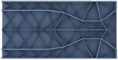
Figure 21:The optimized result of the hierarchical stiffened plate example(I=123.14)
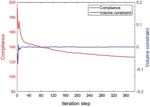
Figure 22: Iteration history of the objective and constraint values of the hierarchical stiffened plate example
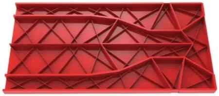
Figure 23:The CAD model of the optimized structure of the hierarchical stiffened plate example
4.4 A Rectangular Stiffened Plate with an Inner Hole Example
In the last example,the stiffener optimization problem of a rectangular plate with an inner hole is considered and the relevant geometry data,boundary conditions and external loads are shown in Fig.24.The thickness of the base panel istp=1.0 and the height of all stiffeners is set ashs=10.The variation range of the thickness ist∈[0.001,4]and the upper bound of the volume occupied by stiffeners is taken as=0.25|D|(|D|=200×100×10).As plotted in Fig.25,the initial design contains 204 components and 76 driven nodes,and the total number of design variables is 328.

Figure 24:The problem setting of the rectangular stiffened plate with an inner hole example
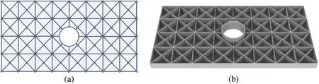
Figure 25:The initial design of the rectangular stiffened plate with an inner hole example:(a)A top view(b)An overall view
The corresponding optimized result with structural compliance ofI=644.97 is exhibited in Fig.26,and the strain energy distribution in the optimized design is depicted in Fig.27.As can be observed from the figures,several thick stiffeners connecting the inner hole region and the fixed support region are generated to effectively transfer the uniformly distributed vertical line load.Furthermore,some thick stiffeners are also generated with a distributive pattern near the hole,which can uniformly diffuse the external loads and significantly increase the local stiffness of the structure.Besides,it can also be clearly seen that the stiffeners in the optimized structure are mainly distributed in regions with high strain energy,which is quite reasonable from a mechanical point of view.As mentioned previously,in the proposed method,the locally refined mesh can be adopted to accurately analyze the local performance of the structure.Accordingly,Fig.28 illustrates the locally refined mesh along the inner hole’s boundary and the optimized design’s stress distribution.The iteration history of the example is depicted in Fig.29.It is worth pointing out that in the present work,both the stiffeners and the inner holes are modeled through the explicit geometry representation.This makes the optimized structure obtained by the proposed method easy to transfer to CAD/CAE systems for subsequent design and manufacturing,as shown in Fig.30.
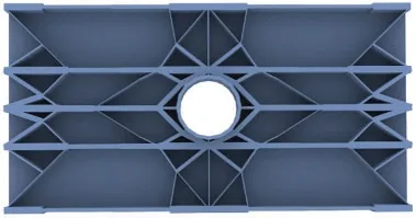
Figure 26: The optimized result of the rectangular stiffened plate with an inner hole example (I=644.97)
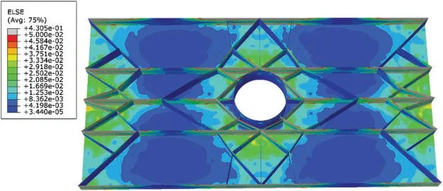
Figure 27:The strain energy distribution in the optimized design of the rectangular stiffened plate with an inner hole example

Figure 28:Locally refined mesh and the stress distribution in the optimized design of the rectangular stiffened plate with an inner hole example:(a)Locally refined mesh along the boundary of the hole(b)The stress distribution in the optimized design
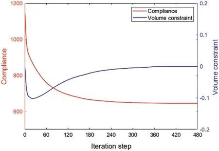
Figure 29: Iteration history of the objective and constraint values of the rectangular stiffened plate with an inner hole example
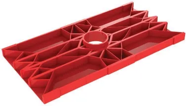
Figure 30:The CAD model of the optimized structure of the rectangular stiffened plate with an inner hole example
5 Concluding Remarks
In this study,a novel approach based on the MMC solution framework for topology optimization of stiffened plate structures is proposed.In this method,all the stiffeners are treated as a set of structural components and the optimal design of stiffened plate structures can be obtained by optimizing the explicit geometry parameters of these components.By adopting Lagrangian type description for geometry representation,an adaptive ground structure method is utilized to regularize the optimization process,while dynamically updated shell elements obtained from an adaptive remeshing technique are adopted for structural response analysis.Under this treatment,not only highly accurate analysis results with relatively low computational efforts can be achieved,but also a clear and clean optimized stiffened structure without extra processing can be obtained.Compared with previous methods,the proposed method has a smaller number of design variables and can accomplish feature size control of the stiffeners easily.Furthermore,various types of stiffened plate structures optimization problems,including straight and curved stiffeners,hierarchical stiffeners,and stiffened plates with cutouts,can be solved uniformly in the proposed explicit topology optimization framework,and numerical examples demonstrate the effectiveness and efficiency of the proposed approach.Last but not least,the generated optimized structures can be seamlessly transferred to CAD/CAE systems,which has a great prospect in industrial applications.As a preliminary attempt,only the minimum compliance optimization problem is considered in the present work and it can be expected that the proposed method has the potential to be applied to other stiffener optimization designs considering complex multi-physics fields,such as acoustic,thermal,etc.Another promising investigation direction is to extend the present work to the stiffener optimization of arbitrary surfaces.Corresponding research results will be reported elsewhere.
Funding Statement: This work is supported by the National Key Research and Development Plan(2020YFB1709401),the National Natural Science Foundation (11821202,11732004,12002077,12002073),the Fundamental Research Funds for Central Universities(DUT21RC(3)076,DUT20RC(3)020),Doctoral Scientific Research Foundation of Liaoning Province(2021-BS-063)and 111 Project(B14013).
Conflicts of Interest:The authors declare that they have no conflicts of interest to report regarding the present study.
Appendix A.Some terms in the expressions of sensitivity analysis
 Computer Modeling In Engineering&Sciences2023年5期
- Computer Modeling In Engineering&Sciences的其它文章
- Towards a Unified Single Analysis Framework Embedded with Multiple Spatial and Time Discretized Methods for Linear Structural Dynamics
- Developments and Applications of Neutrosophic Theory in Civil Engineering Fields:A Review
- Surface Characteristics Measurement Using Computer Vision:A Review
- Recent Progress of Fabrication,Characterization,and Applications of Anodic Aluminum Oxide(AAO)Membrane:A Review
- Challenges and Limitations in Speech Recognition Technology:A Critical Review of Speech Signal Processing Algorithms,Tools and Systems
- Efficient Origin-Destination Estimation Using Microscopic Traffic Simulation with Restricted Rerouting