
Investigation of radial heat conduction with 1D self-consistent model in helicon plasmas
2023-03-09 05:45BinTIAN田滨MarioMERINOJieWAN万杰YuanHU胡远andYongCAO曹勇
Plasma Science and Technology 2023年1期
Bin TIAN(田滨),Mario MERINO,Jie WAN(万杰),Yuan HU(胡远) and Yong CAO(曹勇),∗
1 School of Mechanical Engineering and Automation,Harbin Institute of Technology,Shenzhen,Shenzhen 518055,Peopleʼs Republic of China
2 Equipo de Propulsión Espacial y Plasmas(EP2),Universidad Carlos III de Madrid,Leganés 28911,Spain
3 Laboratory for Space Environment and Physical Sciences,Harbin Institute of Technology,Harbin 150001,Peopleʼs Republic of China
4 State Key Laboratory of High Temperature Gas Dynamics,Institute of Mechanics,Chinese Academy of Sciences,Beijing 100190,Peopleʼs Republic of China
Abstract A 1D radially self-consistent model in helicon plasmas has been established to investigate the influence of radial heat conduction on plasma transport and wave propagation.Two kinds of 1D radial fluid models,with and without considering heat conduction,have been developed to couple the 1D plasma–wave interaction model,and self-consistent solutions have been obtained.It is concluded that in the low magnetic field range the radial heat conduction plays a moderate role in the transport of helicon plasmas and the importance depends on the application of the helicon source.It influences the local energy balance leading to enhancement of the electron temperature in the bulk region and a decrease in plasma density.The power deposition in the plasma is mainly balanced by collisional processes and axial diffusion,whereas it is compensated by heat conduction in the bulk region and consumed near the boundary.The role of radial heat conduction in the large magnetic field regime becomes negligible and the two fluid models show consistency.The local power balance,especially near the wall,is improved when conductive heat is taken into account.
Keywords:helicon discharge,heat conduction,model coupling,plasma transport
1.Introduction
Helicon discharges have been found in recent decades to produce highly ionized plasmas given an appropriate power supply[1,2].A very high plasma density of 1018–1020m−3can be produced and maintained in the laboratory[3,4].Due to this remarkable property,they have been used as plasma sources in diverse areas,from material processing to space propulsion[5].
As an excellent plasma source,there are two main physical processes dominating helicon discharge.Plasma–wave interaction takes place inside the source leading to the deposition of wave energy into the plasma,and multiple transport phenomena govern the plasma dynamics[6].Hence,research on helicon plasmas has mainly focused on these two aspects.However,establishing a complete model for studying these two coupled processes has difficulties and complexities.Researchers tend to investigate each process separately,based on appropriate assumptions about the other.Several 1D and 2D plasma–wave interaction models have been established to investigate the mechanisms of power deposition and wave propagation in helicon plasmas[7–11].For plasma transport processes,the fluid dynamics and transport properties have also been studied with 1D and 2D fluid models[12–16].
Note that all these models mentioned above were developed to study a single process in helicon discharges and based on strong physical assumptions.In the plasma–wave interaction model above,the plasma transport is not taken into account since the profiles of the plasma density and the electron temperature are usually given by the experimental data or assumed distributions[4].Conversely,in most fluid models,the electron temperature is assumed to be uniform[12,15],and the details of the plasma–wave interaction are neglected.However,these two processes are coupled with and influence each other[6].The power deposition of wave energy in the plasma plays an important role in the local energy balance and influences the non-uniformity of the plasma density and the electron temperature.Hence,it is necessary to implement a complete model which couples the plasma–wave interaction model to the fluid model to describe the whole processes.Cho and Lieberman[17]established a 1D self-consistent model,which couples the 1D radial plasma–wave interaction model to the 1D radial fluid model,to investigate the influence of magnetic fields,input power and plasma density on the power deposition and distribution of electron temperature.This model assumed that the influence of heat conduction in the radial direction is trivial and the variation in conductive heat is neglected.Similarly,Curreli and Chen[18]also introduced a 1D self-consistent model without considering conductive losses to investigate helicon plasmas.They explained the reason for the short-circuit effect and how it influences the variation of plasma parameters.Boseet al[19,20]developed a complete 2D helicon plasma model considering heat conduction in the energy equation.Similar 2D self-consistent models were further developed to study helicon plasmas[21–24].In addition,Naulin[25]introduced a 3D global fluid model to simulate a linear helicon device.The numerical results are well consistent with experiments.A 2D-3V particles in cells(PIC)model for calculating a helicon source with a plasma plume was introduced by Takase[26]and Emoto[27].The neutral distribution and characteristics of the magnetic nozzle were investigated by applying this PIC model.More recently,Zhouet al[28]proposed a 2D coupled model for transport and wave propagation,where electron heat fluxes are modeled based on an assumed closure relation.
In helicon plasmas,the influence of heat conduction in the direction perpendicular to the magnetic field lines is generally considered to be inessential because of the assumed good magnetic confinement and relatively low electron temperatures[12,18].However,the confinement depends on the strength of the magnetic field.Moreover,observing the results obtained by Cho and Curreli[17,18],it seems that the electron temperature in the radial direction changes sharply near the boundary although it varies slightly in the bulk region.It is suggested that the local balance of energy would be incomplete without the heat flux term and it is necessary to discuss the effects of the radial heat conduction.Therefore,the motivation of this work is to establish a coupled 1D fluid model with radial heat conduction and a plasma–wave interaction model.This 1D self-consistent model is applied to investigate the effect of heat conduction on steady-state plasma profiles in a helicon source.
In this paper,simulations with and without heat conduction are carried out.The model without radial heat conduction can be seen as a specific case of the fluid model with heat conduction when the perpendicular heat conductivity is zero.Different boundary conditions for these two fluid models are applied near the lateral wall to study their influence.The radial velocity,plasma density and electron temperature are compared and the variation in heat flux is given to analyze the local equilibrium of energy in helicon sources.
The rest of this paper is organized as follows.Section 2 introduces the proposed model in detail.Section 3 shows the results and discussion.The conclusions of this work are gathered in section 4.
2.Model formulation
We consider a cylindrical helicon source of lengthLand radiusrpin a vacuum chamber with the same length and radiusrw.The plasma is confined by an axially uniform magnetic fieldB0.The source is surrounded by an antenna of radiusra,which emits radiofrequency(RF)radiation at angular frequency ω.The neutral gas is ionized by hot electrons,heated by the RF energy and plasma is produced and energized,moving along with magnetic fields.Figure 1 shows the typical geometry of helicon sources.
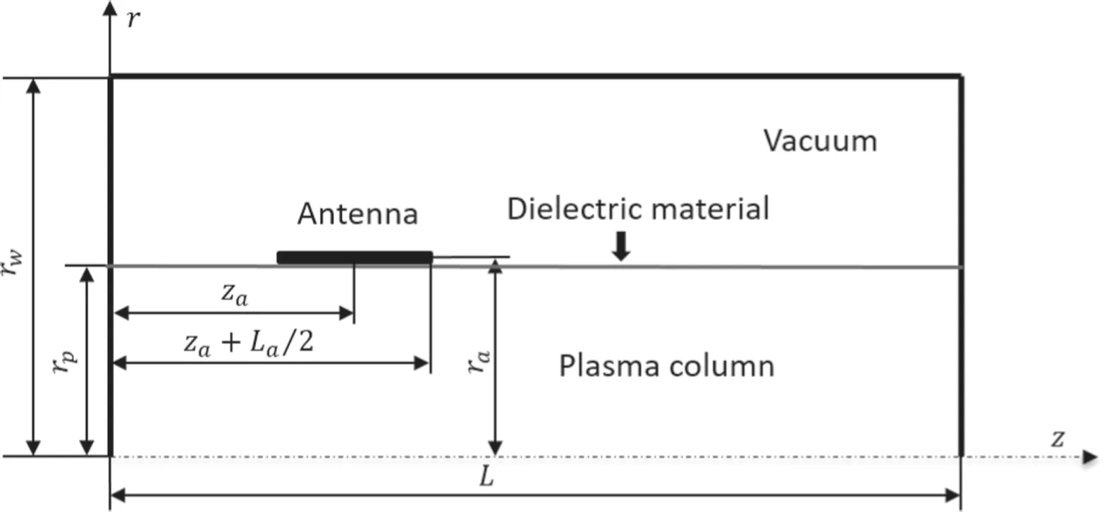
Figure 1.Typical geometry of helicon sources.
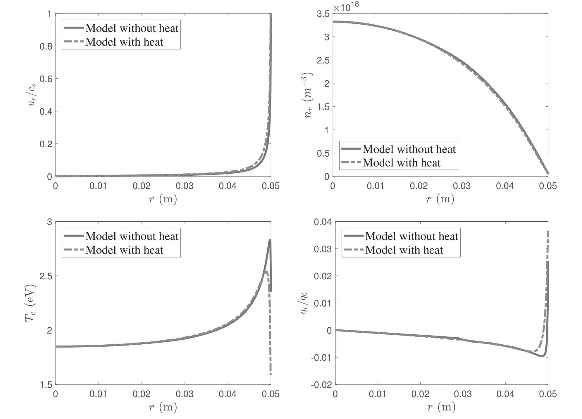
Figure 2.Distribution of plasma parameters in the r direction for the uniform power density profile at B0=300 G and Prf=400 W.The heat flux qr for the fluid model without heat conduction is estimated by numerically differentiating the temperature profile with equation(10).is the reference of the heat flux,with.
For the plasma transport processes,a magnetized and weakly ionized plasma is considered in the helicon source and neutral depletion is not taken into account[12,17].Therefore,the density of the neutral gas is assumed to be uniform.It satisfiespg=ngTg,withpgthe pressure,ngthe density andTgthe temperature of the neutral gas.In addition,quasi-neutrality in plasmas is postulated,with densityn≡ne=ni(subscripts e and i represent electrons and ions,respectively).Therefore,the following steady-state fluid equations are considered to describe the transport processes for each species(j=i,e):
wherenjand ujrepresent the particle density and velocity,respectively;pj=njTjis the pressure;andTjis the temperature.mjandqjare the particle mass and the electric charge,respectively.φ is the ambipolar electric potential and has the relation Ep=−∇φ,with Epthe quasi-electrostatic field induced by the plasma.In addition,Sj=mjnjujνjis the momentum loss for the speciesjdue to different collisional processes,which include ionization and ion–neutral,electron–neutral and electron–ion collisions,with frequencies νion,νin,νenand νei,respectively[15].
For energy conservation,the power deposition and energy transfer in helicon sources are mainly attributed to the interaction of electrons with the wave fields,and the contribution of ions can be neglected.Thus,only the energy equation of electrons is taken into account[20].In equation(3),pabsis the power density absorbed by electrons andplossrepresents the collisional energy loss.The expression and discussion of collisional power loss in this work are given in appendix A.Lastly,Fourier’s law is applied to define the heat conduction in the electrons in order to close the equation system.Qerepresents the heat flux of electrons andis the heat conductivity tensor.
Considering the geometry and physical processes in helicon sources,basic assumptions are proposed to further simplify the equation system:
(1)In cylindrical helicon sources,the axially symmetric geometry leads to the derivative in the azimuthal direction being zero:∂/∂θ=0.
(2)It is assumed that the plasma density can be separated asn(z,r)=f(z)nr(r)in the plasma range due to the variable separation technique[12,15].The normalized functionf(z)tends to have a slight variation in axial length.
(3)As a consequence of quasi-neutrality,it is assumed that the radial velocities of both ions and electrons satisfy the ambipolar diffusion[14,15],withur≡ure=uri.
(4)According to the relation between ions and electrons,withme≪mi,Ti≪Te,electron inertia is neglected and the influence of magnetic fields on ions is negligible so the azimuthal velocity of ionsuθiis not taken into account[14].
(5)It is assumed that the derivatives of parameters satisfy the relations:[15].
Based on these assumptions,the general fluid equations are reduced to the 1D radial fluid model to investigate the influence of the radially conductive heat in helicon sources.Two limit cases,with and without heat conduction,are considered and the details are introduced in the following sections.
2.1.Fluid model with heat conduction
In this part,the 1D radial fluid model with heat conduction is established.Considering the basic assumptions above,the general fluid equations are integrated and averaged in the axial direction in order to eliminate the axial term[17,29].Therefore,equations(1)–(4)are expanded and simplified to
Here,equation(8)is obtained from momentum conservation for electrons in the radial direction.The energy loss due to the electron inertia term is neglected in equation(9)considering its trivial contribution to the whole power loss[15,28].According to different collision processes,we define the total ion collision frequency as νi=νinand the total electron collision as νe=νen+νei.νwis the effective frequency relating to the ionization and axial diffusion[14,15].pcrepresents the collisional energy lossplossaveraged overz.The expressions and explanations for the energy loss and collision frequencies are given in appendix A.Additionally,the averaged power densityis written below:
Here,the radially heat conduction is considered to be dominated by classical diffusion and anomalous diffusion is not taken into account in the heat conductivity due to the presence of magnetic confinement and relatively low electron temperature[19,28].The detailed derivation and discussion ofk⊥are introduced in appendix B.It is noticed that the heat flux tends to be zero when the magnetic field is very large.Then,equations(5)–(10)are combined and derived to the ordinary differential equation system:
This equation system can be solved with boundary conditions to obtain the plasma parameters.
2.2.Fluid model without heat conduction
The 1D fluid model which neglects the heat conduction is described in this part.This can be seen as a specific case for the heat model when the perpendicular heat conductivityk⊥is zero.The conductive loss of heat inrdirection has been ruled out in equation(9),as d(rqr)/d(r)=0.Equation(10)about the heat flux is naturally not taken into account.Therefore,the energy equation reduces to
Then,equations(5)–(8)and(19)constitute the fluid model without heat conduction.Similarly,we derive the ordinary differential equation system to obtain the parameters.The equations related to theuθe,nrand φ are the same with equations(14)–(16)in the heat model and the equations abouturandTe(equations(13)and(18),respectively)are changed to
Therefore,equations(14)–(16)and(20),(21)constitute the ordinary differential equation system of the fluid model without heat conduction.It is applied to discuss the influence of radially conductive heat by comparing with the heat fluid model.
2.3.Boundary conditions
In order to obtain the solution of each fluid model,boundary conditions are applied to implement the whole equation systems.The boundary conditions for the two fluid models are similar.To consider the geometry and characteristics of helicon plasmas,boundary conditions are applied at the cylinder axisr=0 and at the wallr=rp.
We first discuss the boundary conditions for the heat fluid model.At the symmetry axisr=0,plasma parameters satisfy[17]
Here,the valuesTe0andn0are unknown and can be determined by the boundary condition at the wall.Atr=rp,the plasma parameters are governed by the Bohm condition and we have
wherecsis the Bohm velocity and γ is the polytropic index,with γ=1 for the case with heat conduction.Then,the electron heat flux at the sheath edge is written as[29]
wherensrepresents the plasma density at the sheath edge and the conductive energy deposited at the sheath edge is
This expression of the heat fluxqrat the sheath edge is obtained by the integral of the distribution function of the velocity to make sure only the conductive energy is taken into account[30].The derivation and discussion are given in appendix B.Therefore,these two conditions at the wall yield the uniquen0andTe0.
For the model without heat conduction,the boundary conditions atr=0 are the same as for the heat model except that the heat flux is not taken into account.It is also necessary to obtain the value of the density and temperature at the axis.Therefore,the Bohm condition at the wallr=rpis applied.Here,the polytropic index γ is 5/3 for the model without heat conduction due to the adiabatic approximation[17].Thus,the plasma velocity atr=rpis written as
Because the heat conduction is not considered,equation(23)is not satisfied for the model without heat conduction.Therefore,the local balance of energy at the axis(r=0)is applied as the other boundary condition to implement the equation system.Equation(19)atr=0 can be simplified to[17]
For a given profile of power density,the electron temperatureTe0can be written as a function of the plasma densityn0by using this relation.Then,the integration of fluid equations from the origin to the wall yields the uniquen0to satisfy the Bohm condition.It should be noted that the local equilibrium relation of equation(26)is not satisfied for the heat model since the derivative of heat flux at the origin is uncertain.
2.4.Plasma–wave interaction model
The 1D plasma–wave interaction model which is applied to couple the 1D fluid model has been introduced by numerous authors[7,8,31]and is described here to give a general framework to explain how it is established and works.It is assumed that the plasma–wave response varies asexp(−iωt)and is governed by the Maxwell equations
where E and B represent only the RF-related electromagnetic field,jais the external current density and μ0is the permeability in a vacuum.Additionally,is the electric displacement field,with ∊0the permittivity in a vacuum andthe dielectric tensor in the medium.Fourier expansion in time has been applied,and all magnitudes are expressed in complex form.All parameters of plasmas,such as the plasma density,the temperature and the applied magnetic field,are loaded in the Maxwell equations by the cold,collisional dielectric tensor[7].
According to the finite length helicon source and the reflecting boundary condition at the conducting end wall,all quantities in thezand θ directions can be expanded as sin or cos series for integer modes as(l,m).Hence,applying the new expressions,the Maxwell equations are rearranged into four differential equations and two algebraic equations[31].The set of equations can be solved numerically as an ordinary differential problem in radially uniform and non-uniform plasmas and all electromagnetic(EM)field components can be obtained.
Then,once all fields have been calculated,it is necessary to consider the power deposition in the plasma.Here,it is assumed that the antenna is a perfect conductor and there is no power loss in it[7,11].All RF powerPrfemitted by the antenna is absorbed by the electrons.Therefore,the total powerPtotaldeposited in the plasma is equal to the RF power,as
2.5.Numerical procedures
In this part,the numerical procedures for obtaining solutions in this work are described.The fluid models and the plasma–wave interaction model can be solved independently with appropriate initial conditions if only a single process is concerned.For the fluid models,the equation system has singularity at the origin.In order to carry out the numerical integration from the axis,it is necessary to use the Taylor expansion for the variables aroundr=0[14,17]:
Based on these initial values,the shooting method is used and the equation system is integrated from the axis to the wall to obtain the complete solutions.
Meanwhile,the iteration process can be carried out to couple the two models and obtain the self-consistent steady-state solution.It is noticed that the two fluid models follow the same iteration process.When the given profiles ofnrandTeare considered to be the initial conditions,the plasma–wave interaction model is first solved and the iteration steps are as follows:
Step 1:Applying the profiles ofnrandTein the wave model,obtain the solution of EM fields and the power densityPabs.
Step 2:Applying the distribution ofPabsin the fluid model,solve the fluid equations and update the parametersnrandTe.
Step 3:Comparing the updated profiles ofnrandTewith old profiles,the iterative process is finished if the convergence is achieved.If not,the iteration returns to step 1 to continue the iteration.
In addition,the fourth-and fifth-order Runge–Kutta methods,which are mature methods for solving ordinary differential problems,are applied in the fluid and wave module to obtainthe solution.This self-consistent process has been introduced theoretically by Researchers[17,32]and the numerical results have been verified by comparing with experiments[18,33].
Table 1.Summary of input data for the numerical simulations.
3.Results and discussion
The numerical results are described and discussed in this section.The simulations are based on a typical helicon source geometry which is immersed in a cylindrical vacuum chamber shown in figure 1.The main parameters are summarized in table 1.A Nagoya III antenna is applied to ionize and heat plasmas with emitting RF waves of frequency 27 MHz.The input RF power is 400 W.It is assumed that the antenna wire is a perfect conductor with no resistance.Considering the specific structure of the Nagoya III antenna,the expression of the current density is written as a function of the(l,m)modes and only odd modes ofmare effective[7,8].The antenna is located in the center of the chamber and the length is 1/4 of the chamber length.Hence,due to the non-zero modes and main contribution of the(l,m)mode,l=2,4,6 andm=−1,1 modes are taken into account in the simulations[17].In the following discussions,we first present results for the transport model assuming a uniform power deposition profile,and for the electromagnetic model assuming different density profiles to obtain non-uniform power deposition profiles.Then,the self-consistent results of the two coupled models are discussed.
3.1.Uniform power deposition
In this subsection,the fluid model is solved independently,assuming a uniform power distribution is given.The iteration process in this part is not taken into account in order to observe the effects of conductive heat directly.
Figures 2 and 3 show the distributions of plasma parameters in the radial direction for two different cases atB0=300 G and 50 G,respectively.For the model without heat conduction,the heat flux is not taken into account.In order to compare with the heat model,we estimate the distribution of the heat fluxqrfor the model without heat conduction shown in the figures by differentiating the temperature profile with equation(10).It is shown that the basic trends of all results obtained by the two models are consistent and the influence of the heat conduction at low magnetic fields is moderate.
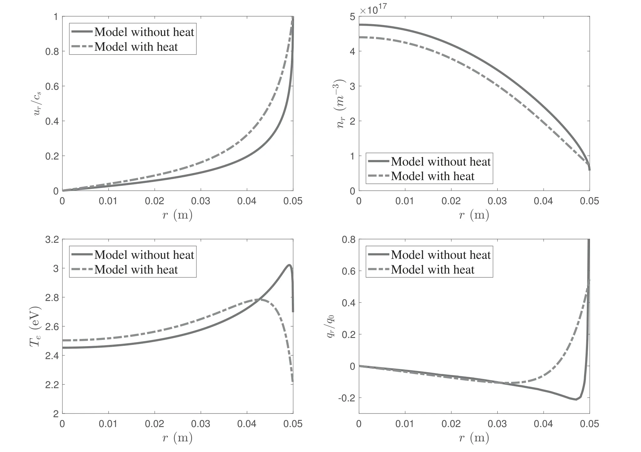
Figure 3.Distribution of plasma parameters in the r direction for the uniform power density profile at B0=50 G and Prf=400 W.The heat flux qr for the fluid model without heat conduction is estimated by numerically differentiating the temperature profile with equation(10).q0=n0Te0c0 is the reference of the heat flux,with.
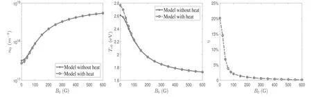
Figure 4.Plasma density and electron temperature in the center(r=0)varying with magnetic field at Prf=400 W.η represents the ratio of the term associated with heat conduction to the power deposition as defined in equation(37).
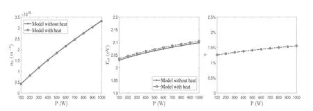
Figure 5.Plasma density and electron temperature in the center(r=0)varying with input power at B0=150 G.η represents the ratio of the term associated with heat conduction to the power deposition as defined in equation(37).
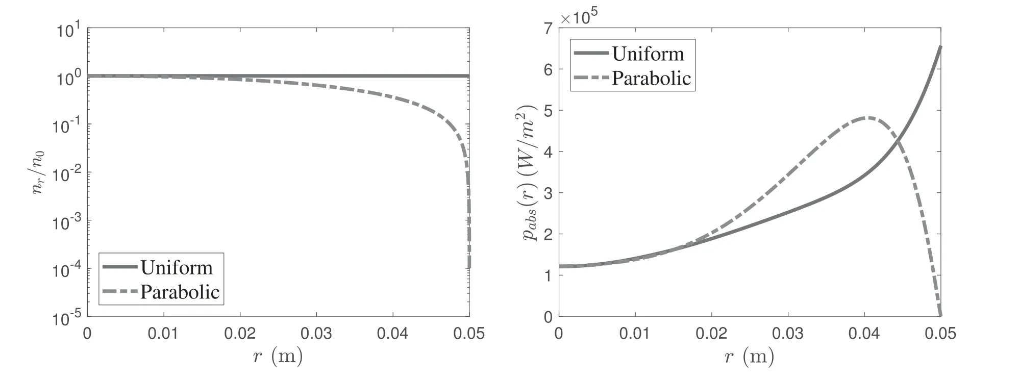
Figure 6.Different density profiles and corresponding power absorption in the radial direction at B0=100 G and Prf=400 W.The plasma density and the electron temperature at r=0 are n0=1.3×10¹⁷ m−3 and Te0=2 eV,respectively.
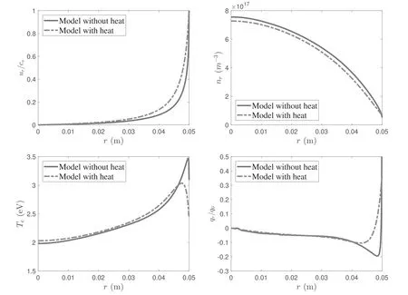
Figure 7.Distribution of plasma parameters in the r direction for the uniform plasma density profile at B0=100 G and Prf=400 W.The plasma density at r=0 is n0=1.3×10¹⁷ m−3 and the electron temperature is Te0=2 eV.The heat flux qr for the fluid model without heat conduction is estimated by numerically differentiating the temperature profile with equation(10). q0=n0Te0c0 is the reference of the heat flux,with.
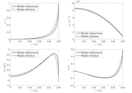
Figure 8.Distribution of plasma parameters in the r direction for the parabolic plasma density profile at B0=100 G and Prf=400 W.The plasma density at r=0 is n0=1.3×10¹⁷ m−3 and the electron temperature is Te0=2 eV.The heat flux qr for the fluid model without heat conduction is estimated by numerically differentiating the temperature profile with equation(10). q0=n0Te0c0 is the reference of the heat flux,with.
AtB0=300 G,the plasma is mainly confined in the bulk region due to the strong magnetic field strength,so that the radial velocityurchanges slightly and sharp variation occurs near the boundary to satisfy the Bohm condition.Moreover,the profiles of the electron temperature and heat flux show similar trends.The local peak of electron temperatures occurs near the boundary.The decrease inTenear the wall is caused by the temperature difference between the plasma and the lateral wall.To observe the results of different models,the heat conduction has a slight influence in terms of the confinement of the magnetic field.The distributions ofurandnrare nearly the same in the whole plasma region and the difference is less than 2%.The main difference appears in the profile ofTenear the boundary.Because of the effects of heat conduction,the local peak of the electron temperature near the boundary is lower than for the model without heat conduction.
In contrast,the influence of heat conduction plays a relatively important role atB0=50 G.The plasma densitynrobtained by the heat model is lower than for the model without heat conduction.For the electron temperatureTe,it is also higher in the bulk region and sharply decreases near the boundary.The difference between the plasma density of the two models at the axisn0is about 8.2% and that of the electron temperatureTe0is about 2%.However,the difference becomes larger near the wall.In particular,for the electron temperature,it reaches 18%,about 0.5 eV.In addition,the normalized plasma velocity obtained by the heat model is higher.This proves that the influence of the radial heat conduction in the low magnetic field is moderate.The importance depends on the application of the helicon source.For plasma etching and material surface treatment,the performance is more sensitive for the plasma parameters of the helicon source and has a very high requirement in parameter control[34].Therefore,the effects of the radial heat conduction cannot be neglected.However,for the new concept of space propulsion,the helicon plasma thruster,the radial heat conduction could hardly play a significant role if the differences in the central plasma density and the electron temperature are too low[16].
In figure 3,the heat fluxqrkeeps consistency with the estimated value in the bulk region and changes significantly near the wall due to the variation inTe.It is noticed that the heat flux is negative in the bulk region and varies to be positive near the wall.This illustrates that the conductive energy flux flows to the center in the bulk region and to the wall near the boundary.The energy is carried into two sides of the local peak.Therefore,the local energy equilibrium is changed due to heat conduction and leads to a decrease in the plasma density and the variation in electron temperature.
To further clarify the influence of heat conduction,the density and electron temperature in the center(r=0)varying with magnetic field and input power are shown in figures 4 and 5.With an increment in magnetic field and input power,the two models show consistency.The initial plasma densityn0becomes larger and the initial electron temperatureTe0reduces accordingly as the magnetic field increases in figure 4.It is concluded that increasing the magnetic field is beneficial for improving the plasma density in helicon sources,which has been proven in numerous experiments and simulations[17,35].This is a typical principle for discharge where the plasma is weakly ionized[34].In figure 5,it is shown thatn0increases linearly andTe0tends to be constant with a variation in input power.These results suggest that the relation betweenn0andTe0is determined by the local equilibrium of energy.For the fluid model without heat conduction,the local power balance atr=0 satisfies equation(26).Substituting equation(A.10)to equation(26),it can be rewritten as
This relation shows that the power deposition in the center is mainly balanced by the collision processes and the axial diffusion.Considering each term in the right side of equation(32)given in appendix A,the local balance can be simplified to
Therefore,it is clearly indicated that the power density in the center is proportional to the initial plasma densityn0and dependent on a function of the initial electron temperatureTe0.This is consistent with the results shown in figures 4 and 5.In addition,for giving a specific input power in the center,largern0implies that more energy is applied to ionize the neutral gas andTe0yields to diminish correspondingly.As the magnetic field increases,the confinement of electrons becomes stronger and suppresses the diffusion of electrons in the radial direction.This leads to more collisions in the bulk region and enhances the ionization of the neutral gas.
This principle is not only satisfied in the fluid model without heat conduction but also in the heat model.Considering the influence of the heat flux,equation(26)is modified to
Combining equation(10),it is further derived as
Due to the smooth condition of temperature atr=0 as dTe/dr=0,and the expression ofk⊥given in equation(12),this relation also can be written as the densityn0multiplied by a function ofTe0.Hence,the power deposition is balanced by
This equation shows that the power deposition in the center also has a linear relation with the plasma density and is mainly consumed by particle collisions and axial diffusion.However,it is compensated by the heat conduction of electrons in the center.This is the reason why the higher electron temperatures atr=0 for the heat model are achieved at low magnetic fields.In order to evaluate the influence of the heat flux,the contribution of the conductive heat to the power deposition is defined as
Thus,the percentages of the conductive heat η for different magnetic fields and input power have also been given in figures 4 and 5.It is shown that η decreases evidently with increasingB0.The contribution of the conductive heat is higher than 20%atB0=0 and less than 1%whenB0is larger than 200 G.This is because the radial heat conductivityk⊥is inversely proportional toshown in equation(12)and tends to be zero whenB0is large.Therefore,the results ofn0andTe0for the two models in figure 4 becomes consistent whenB0is large.For the variation in the input power,η is almost a constant because of the invariant magnetic field.
In summary,the local power deposition is mainly balanced by collisional processes and axial diffusion.It is compensated by the heat conduction in the bulk region and consumed near the wall.The conductive heat plays a relatively important role in the local power balance for helicon plasmas when the magnetic field is small.The power deposition in the center is proportional ton0and dependent on a function ofTe0.With magnetic fields,the increasing input power mainly applies in the processes of collision to ionize the neutral gas and hardly contributes to heating electrons.
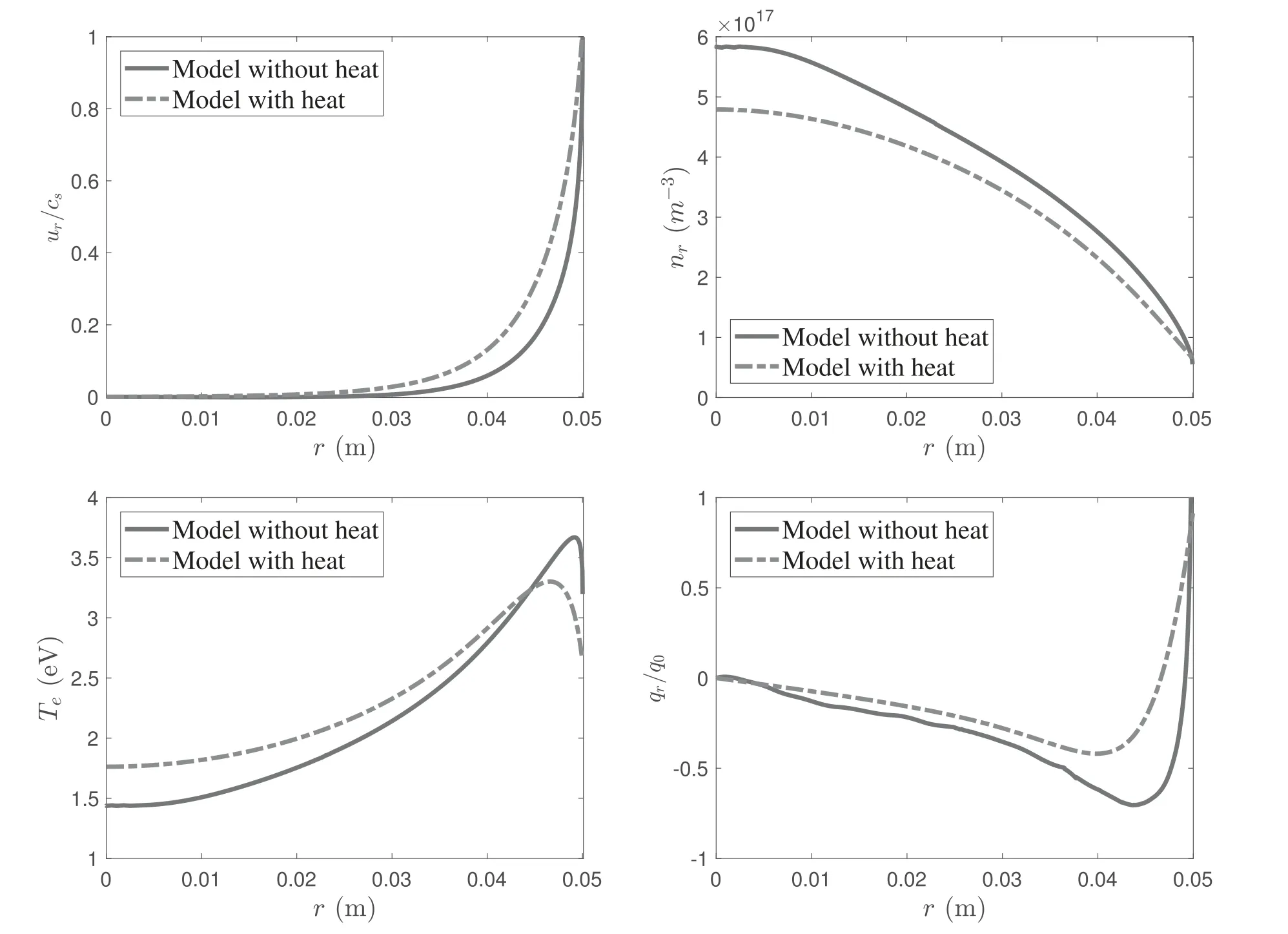
Figure 9.Self-consistent solutions of plasma parameters in the r direction for the parabolic plasma density profile at B0=75 G and Prf=400 W.The plasma density at r=0 is n0=5.7×10¹⁷ m−3 and the electron temperature is Te0=2 eV.The heat flux qr for the fluid model without heat conduction is estimated by numerically differentiating the temperature profile with equation(10).q0=n0Te0c0 is the reference of the heat flux,with.
3.2.Non-uniform power deposition
In this part,different density profiles and uniform electron temperatures in the radial direction are chosen to be the initial conditions of the wave model in order to obtain the non-uniform power depositions,which are applied to the fluid model as the input data.Still,we are not solving the selfconsistent solutions.A comparison between different fluid models is carried out to investigate the influence of heat conduction.Here,the uniform and parabolic density profiles,which are commonly used in helicon plasma simulations[7,17],are considered to be the initial conditions of the wave model.
The density profiles and power absorptions in therdirection are shown in figure 6.It is concluded that the influence of density profiles on the power deposition is evident and it leads to different power density profiles in therdirection.Therefore,the fluid model is expected to be affected by the large difference in power deposition.Figures 7 and 8 show the plasma parameters in the radial direction for different density profiles.It is observed that the trends of parameters using uniform density profile in figure 7 are similar with previous results from the uniform power density profile.However,the electron temperatureTeincreases gradually in the bulk region due to the increment of power density and the local peak is narrow.This is because the electron temperatureTeis affected by the power deposition profile.It is further confirmed by the results obtained from the parabolic plasma density profile shown in figure 8.The variation inTeis highly relevant to the power density distribution and it also influences the densitynr.With the fluctuation ofPabs,the electron temperatureTehas similar trends and a wider local peak is achieved.The profile of the heat flux in the radial direction also reflects the variation in temperature.
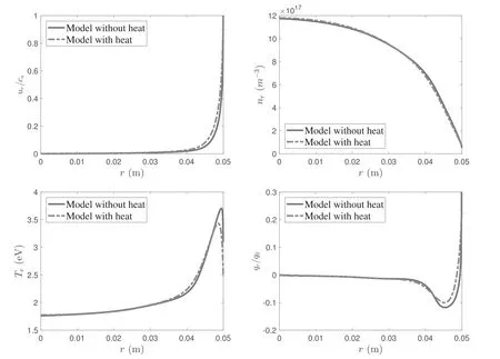
Figure 10.Self-consistent solutions of plasma parameters in the r direction for the parabolic plasma density profile at B0=200 G and Prf=400 W.The plasma density at r=0 is n0=5.7×10¹⁷ m−3 and the electron temperature is Te0=2 eV.The heat flux qr for the fluid model without heat conduction is estimated by numerically differentiating the temperature profile with equation(10). q0=n0Te0c0 is the reference of the heat flux,with.
In addition,the comparison of the two fluid models is consistent with the previous analysis.Due to the influence of heat conduction,the temperature difference causes the heat flux to move toward the central area in the bulk region,which makes the central area obtain the compensation of energy.This leads to variation in the local energy balance and the density of the heat model is generally lower than the results of the model without heat conduction.Moreover,the corresponding temperature is higher than that of the model without heat conduction in the bulk region and the local peak ofTeis generally lower.
3.3.Self-consistent results
Finally,the self-consistent results for two models coupled together are compared and discussed.The parabolic plasma density and uniform electron temperature profiles are used to be the initial conditions in the wave model and the fluid model is calculated by applying the results from the wave part.Then,the iteration process is carried out until convergence is achieved.Figures 9 and 10 show the self-consistent results for different magnetic fields.It is clearly shown that the strength of applied magnetic field determines the effect of the radial heat conduction.AtB0=75 G,the radial heat conduction plays a relatively important role in helicon plasmas and influences the plasma parameters moderately.The plasma density is reduced and higher normalized plasma velocity is achieved in the heat model.The electron temperatureTeis raised in the bulk region and has a lower and wider local peak than that of the model without heat conduction near the boundary.The local energy equilibrium is varied if the heat conduction is taken into account.AtB0=200 G,the confinement is strengthened and causes the radial heat conduction to become weaker.The heat fluxqris much smaller thanB0=75 G and the results obtained from the two models are almost consistent except that the local peak ofTeis slightly lower.
Therefore,the self-consistent results for non-uniform plasma density profiles further confirm that heat conduction has a moderate effect in the low magnetic field range.However,the importance depends on the application.In space propulsion,the differences in the plasma density and the electron temperature due to the radial heat conduction for the helicon plasma thruster are not large enough to clearly influence the thrust and efficiency[16].However,plasma etching and material surface treatment require high uniformity and precise parameter control[34].Radial heat conduction plays a significant role and cannot be neglected in these areas.Meanwhile,the trends of both the heat model and the model without heat conduction are consistent whenB0is large enough.However,the model without heat conduction misses the details of the variation in electron temperature near the wall and the local energy equilibrium is improved in the heat model by considering conductive energy variation.
4.Conclusion
A 1D radially self-consistent model,which couples a 1D radial fluid model to the corresponding plasma–wave interaction model,has been established in this paper.Two different fluid models,with and without considering conductive heat,have been taken into account to investigate the influence of the heat conduction.The steady-state profiles of the plasma properties and the power absorption have been obtained and discussed for different values of the magnitude of the applied magnetic field.It is concluded that radial heat conduction plays an moderate role at low magnetic fields and the necessity depends on the application of the helicon source.The power deposition is mainly balanced by collision processes and axial diffusion.Heat conduction tends to unify the electron temperature profile.In practice,this means that it increases the electron temperature near the axis,and it decreases the peak that appears in the vicinity of the lateral wall.The heat losses to the walls are naturally enhanced too.Therefore,the plasma density is reduced and the electron temperature becomes smoother accordingly.Furthermore,the local peak of the electron temperature near the wall is lower and wider.
With increasing magnetic field,the contribution of the conductive heat to the energy balance becomes negligible and the difference between the two models is trivial.It is shown that two 1D models are both appropriate to describe the radial variation of helicon plasmas in large magnetic field ranges,but the local power balance is improved in the heat model by considering the variation in heat conduction.
In the future,a 2D self-consistent model considering both the perpendicular and the parallel heat conduction in helicon sources should be established to investigate the conductive heat flux in the whole region.The parallel heat conduction along the magnetic field will strongly influence the energy transfer in plasma transports and the effects of heat conduction in the perpendicular direction should be discussed in nonuniform magnetic fields.In addition,the anomalous transports perpendicular to the magnetic field and the instability affecting heat conduction are worth analyzing.
Acknowledgments
This work was supported by National Natural Science Foundation of China(No.51907039)and Shenzhen Technology Project(Nos.JCYJ20190806142603534 and ZDSYS201707280904031).Mario Merino’s contribution was supported by the ESPEOS project(No.PID2019-108034RB-I00/AEI/10.13039/501100011033),funded by the Agencia Estatal de Investigación(Spanish National Research Agency).
Appendix A.Collision frequency and power loss
The collisional parameters considered in this work are given in this part.First,the collision frequencies including ionization and electron–neutral,ion–neutral and electron–ion collisions are written below,respectively[15,34]:
Table A1.Values of gas-dependent parameters for argon[34,37].
wherengrepresents the density of neutral gas,Eionis the first ionization energy,and σionand σenare the collisional cross sections for ionization and electron–ion collision,respectively.k1andk2are the corresponding coefficients in ion–neutral collisions.All parameters mentioned above are dependent on the type of gas and summarized in table A1.Additionally,uin=|ui−un| is the relative velocity between ions and neutrals.In electron–ion collisions,Λ is the parameter depending on the electron density and temperature[15].
In equation(5),the effective frequency νw,which is related to the ionization and axial diffusion,is applied to implement the continuity equations.The expression of νwis derived as[12,17]
The second term of the right side of equation represents the axial diffusion.is the average density in thezdirection and can be equal to 1 if the variation of the axial density is assumed to be small.andfsare the velocity and the normalized density at the axial sheath.In low-pressure gas discharges,the expression offsis obtained as[17,36]
where λiis the mean free path of ions.
Next,the power loss due to collisions is discussed to satisfy the local energy balance of plasmas.According to the collision processes,it can be written as[34,37]
where theEseries is the energy loss of each electron and the subscripts represent ionization,excitation,metastable creation and elastic collisions,respectively.TheKseries is the corresponding rate of collisions and depends on the electron temperature.The expression is written as[34,37]
The parameters σxandExare dependent on the gas type.For argon,they are shown in table A1.To averageplossoverzand consider the energy loss in the diffusion,
whereqzis the heat flux in the axial direction.The second term of integration is obtained from the left side of equation(3).Substituting equation(A.7)and considering the conductive energy of electrons at the axial sheath,equation(A.9)can be further simplified to[17]
whereEwis the conductive energy of the electron flux deposited at the sheath edge.
Appendix B.Radial heat conduction
Here,we consider the stationary heat transport equation in collisional plasmas to derive the heat conductivities in the radial direction.It is given as[30,38]
It is assumed that the derivatives ofTein the axial and azimuthal directions are negligible.Equation(B.1)can be expanded as
Substituting equation(B.3)into equation(B.2),the relation betweenqrandTeis obtained as
Therefore,the radial heat conductivityk⊥is given in equation(B.4).
Next,the radial heat fluxqrat the sheath edge is discussed to implement the boundary condition of the fluid model.In references[17,29],the heat fluxqrat the sheath edge is given as
where the energy term εeis the total energy of electrons at the sheath edge.This means that not only conductive energy but also convective energy is contained in the energy term.However,the heat fluxqronly represents the conductive energy flux and has to differ from the total energy flux of electrons.Therefore,we derive the heat fluxqrat the sheath edge(r=rp)from the definition[30]
wherevris the velocity of electrons in the radial component,uris the corresponding fluid velocity andVsis the cut-off velocity to rule out the electrons absorbed by the wall.g(vr)is the distribution function of velocities.It is assumed that electrons satisfy the Maxwellian distribution function
Then,the cut-off velocity can be obtained from the electron velocity at the sheath edge,
Substituting equation(B.7)into equation(B.8),Vsis given as
Applying this relation,equation(B.6)can be integrated into
whereEwis the conductive energy of electrons deposited at the sheath edge.Considering the relation,mi≫me,Ewcan be further simplified to
Therefore,the heat fluxqrat the sheath edge has been obtained and separates the conductive energy from the total energy of electrons.It also can be applied to the axial heat fluxqzat the sheath edge in equation(A.9).
 Plasma Science and Technology2023年1期
- Plasma Science and Technology的其它文章
- Development of miniaturized SAF-LIBS with high repetition rate acousto-optic gating for quantitative analysis
- Rotor performance enhancement by alternating current dielectric barrier discharge plasma actuation
- A nanoparticle formation model considering layered motion based on an electrical explosion experiment with Al wires
- Focused electron beam transport through a long narrow metal tube at elevated pressures in the forevacuum range
- A study of the influence of different grid structures on plasma characteristics in the discharge chamber of an ion thruster
- High-resolution x-ray monochromatic imaging for laser plasma diagnostics based on toroidal crystal