
Temporal electric field of a helium plasma jet by electric field induced second harmonic(E-FISH)method
2023-03-09 05:45XuLI李旭ShaohuiJIN晋绍珲KeSONG宋珂LanlanNIE聂兰兰DaweiLIU刘大伟andXinpeiLU卢新培
Plasma Science and Technology 2023年1期
Xu LI(李旭),Shaohui JIN(晋绍珲),Ke SONG(宋珂),Lanlan NIE(聂兰兰),Dawei LIU(刘大伟) and Xinpei LU(卢新培)
1 State Key Laboratory of Advanced Electromagnetic Engineering and Technology,School of Electrical and Electronic Engineering,Huazhong University of Science and Technology,Wuhan 430074,People’s Republic of China
2 Center of Stomatology,Tongji Hospital,Tongji Medical College,Huazhong University of Science and Technology,Wuhan 430030,People’s Republic of China
3 School of Stomatology,Tongji Medical College,Huazhong University of Science and Technology,Wuhan 430030,People’s Republic of China
Abstract Electric field is an important parameter of plasma,which is related to electron temperature,electron density,excited species density,and so on.In this work,the electric field of an atmospheric pressure plasma jet is diagnosed by the electric field induced second harmonic(E-FISH)method,and the time-resolved electric field under different conditions is investigated.When positive pulse voltage is applied,the electric field has a peak of about 25 kV cm−1 at the rising edge of the voltage pulse.A dark channel is left behind the plasma bullet and the electric field in the dark channel is about 5 kV cm−1.On the other hand,when negative pulse voltage is applied,the electric field has a peak of −16 kV cm−1 when the negative voltage is increased to−8 kV.A relatively bright channel is left behind the plasma head and the electric field in this relatively bright channel is about −6 kV cm−1.When the pulse rising time increases from 60 to 200 ns,the peak electric field at both the rising edge and the falling edge of the voltage decreases significantly.When 0.5% of oxygen is added to the main working gas helium,the peak electric field at the rising edge is only about 15 kV cm−1.On the other hand,when 0.5% nitrogen is added,the peak electric field increases especially at the falling edge of the voltage pulse,where it increases reversely from −12 to −16 kV cm−1(the minus sign only represents the direction of electric field).
Keywords:atmospheric pressure plasma jet,electric field,electric field induced second harmonic
1.Introduction
Atmospheric pressure plasma jets(APPJs)have attracted lots of interest in the past decades due to their urgent applications[1–18].To better understand the plasma characteristic,novel plasma diagnostic methods are needed.The main plasma parameters include the electron density,electric field,electron temperature,reactive oxygen species density,and so on[19–21].Among these parameters,electric field is one of the most important parameters,which is related to the dynamic process of electron and high energy electron distribution[22].
On the other hand,it is extremely difficult to measure the electric field of APPJs.Recently,several methods for atmospheric pressure plasma electric field diagnosis have been proposed,such as the electro-optic probe method[18]and optical emission spectroscopy method[23–25].However,the electro-optic probe usually needs to invade into plasma,which interferes with the gas flow.Surface charge accumulation on the probe also affects the plasma characteristic.Regarding the optical emission spectroscopy method,it cannot be applied when the optical emission of the plasma is weak.For example,it cannot be used to diagnose the electric field of the dark channel of a plasma jet.In addition,it requires that the excited states are generated by electron collision excitation rather than excited by metastable state species.
Recently,an electric field diagnosis method based on the electric field induced second harmonic(E-FISH)method was proposed[26–30],which has been used to measure the nonlinear polarization coefficients of different gas components,static electric field of DC corona,transient electric field of dielectric barrier discharge and blade electrode discharge[27–30].The main advantages of E-FISH are its high spatial and temporal resolution.Additionally,it can be used to measure the electric field for most situations;the working gas of the plasma can be molecular gas or atomic gas.In addition,the electric field components in different directions can be obtained by using a laser with different polarizations.Furthermore,the measurement does not depend on the optical emission of the plasma;thus,it can be used to measure the electric field of nonluminous regions such as the dark channel of APPJs.
In this work,an E-FISH method based on a nanosecond pulse laser is used to obtain the time-resolved electric field of APPJs driven by positive or negative pulse voltage.Additionally,the effects of the percentages of nitrogen and oxygen mixture of a helium plasma jet on the temporal behavior of the electric field are investigated.
2.Experimental setup
The E-FISH method is used to obtain the time-resolved electric field of a helium plasma jet.When a laser passes through a nonlinear medium,an external photoelectric field interacts with molecules,atoms and electrons in the plasma to produce a polarized photoelectric field.This field is expressed by the electric polarization intensityPin the strong field environment.When the laser is in a strong electric field,there is a nonlinear optical effect and the field induced second harmonic corresponds to the third-order nonlinearity[31,32].E-FISH generation can be described as a third-order nonlinear process involving both a light field and an external electric field[26]:
In the process of light propagation,the relationship between light field intensity and polarization intensity can be described in the form of a Maxwell wave equation,which for the second harmonic intensitycan be written as:
whereAis the calibration constant,which is calibrated with a known electric field,and all unknown parameters are included in the calibration constant.
During the experiment,the Rayleigh lengthZRdetermines the spatial resolution along the laser direction and the resolution in the vertical laser direction is determined by the waist diameter of the laser beam.The beam waist diameter is affected by the laser itself and the focusing ability of the focusing lens.The strong focusing ability makes the beam waist diameter smaller and the spatial resolution higher.However,the strong focusing of the laser increases the energy density,thus increasing the risk of photo-breakdown.Finally,a focusing lens with focal length of 10 cm is selected,and the corresponding Rayleigh length is 2 mm.
In this experiment,a Nd:YAG nanosecond pulse laser is used as the pump laser.It has a frequency of 10 Hz,pulse width of 8 ns,wavelength of 1064 nm,and energy per shot of 60 mJ during the measurements.A long pass filter(LP,through above 950 nm)is used to filter out the mixed 532 nm light and other stray light.A half wave plate(HWP)is used to change the laser polarization direction from horizontal polarization to vertical polarization,so the electric field along the vertical direction is measured.Then the laser focuses through a focus lens(FL)with a focal length of 10 cm.The focus should be located in the center of position to be measured,so as to ensure the Rayleigh range covers the region of the electric field.After the laser passes through the center area,a collimator lens(CL)is used to change the laser back to parallel light,and a 532 nm reflector mirror(HF)is used to separate the E-FISH signal from the source laser.The laser emission is collected by a beam dump.The E-FISH signal is further filtered by a spectrometer and finally collected by an ICCD camera.
Because the E-FISH signal is weak,especially measured in helium,it is essential to reduce stray noise and increase the signal-to-noise ratio of E-FISH.Firstly,strict time synchronization should be carried out.The flash lamp and Q-switch of the laser are synchronized with the nanosecond pulse power supply and the ICCD camera through a digital delay generator(DG645).The exposure time of the ICCD camera is set to be the same as the laser pulse width to minimize stray light.Secondly,the refractive index of the collimator lens is slightly different between 1064 nm and 532 nm,and the position of the lens needs to be adjusted to ensure E-FISH light is accurately collimated.Then,the E-FISH signal is separated by a high-reflectivity mirror and focused into spectrometer by a focus lens.Finally,the signal is accumulated 600 times to enhance the intensity of E-FISH and reduce the measurement error.Figure 1 shows a schematic of the experimental setup.
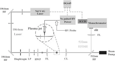
Figure 1.Schematic of the experimental setup.The red line indicates the fundamental frequency laser;the green line indicates the second harmonic signal;the dotted line indicates the trigger signal;HF—high reflector mirror;LP—long pass filter;HWP—half wave plate;FL—focusing lens;and CL—collimating lens.The red point or red arrow indicates the polarization direction of the laser.
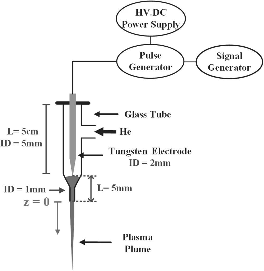
Figure 2.Schematic of the plasma jet device.Position at the nozzle is labeled z=0 mm.
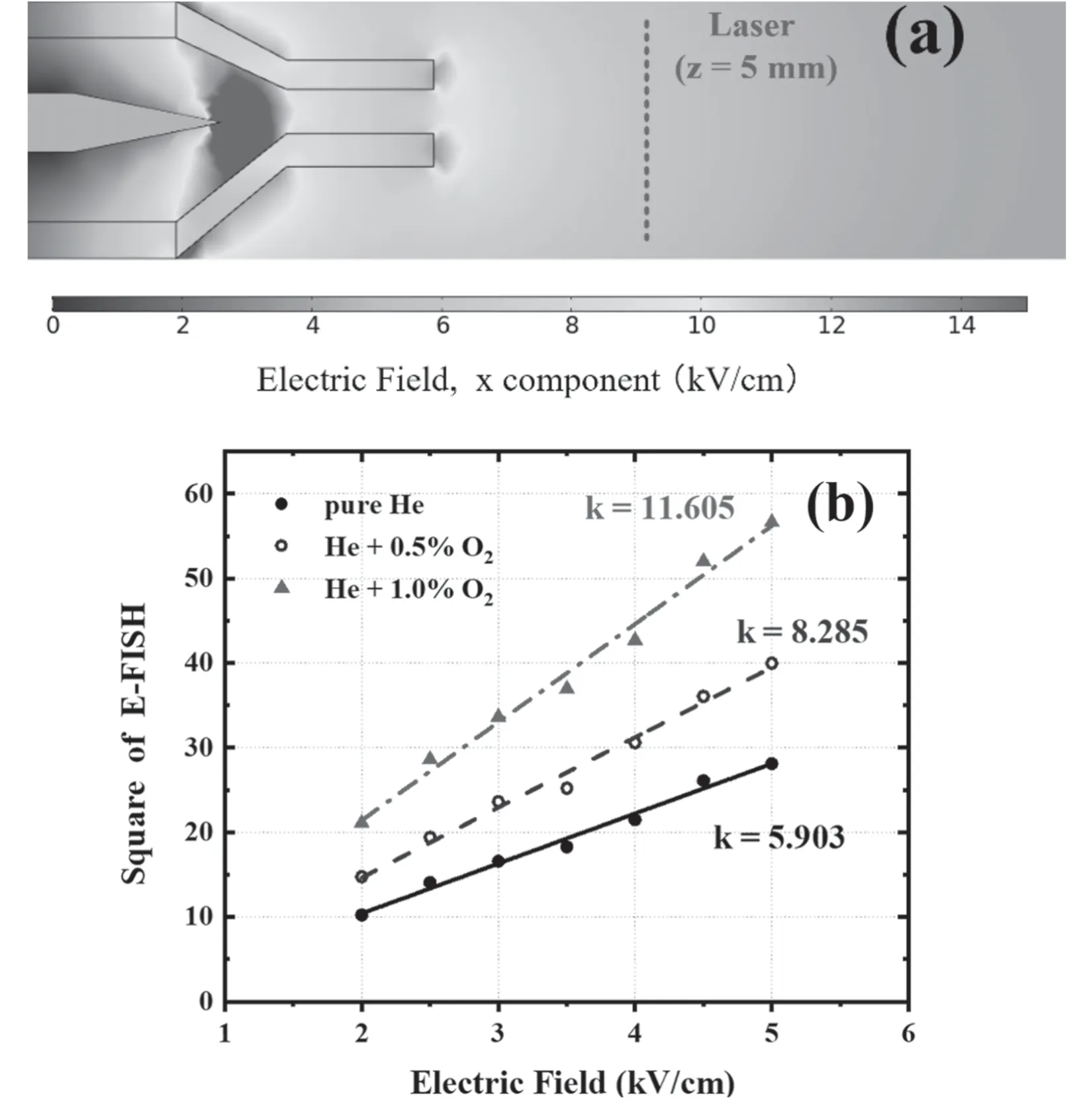
Figure 4.(a)Simulation results of the electric field when no plasma is generated.The applied voltage is 8 kV and the dotted red line indicates the laser position where it is 5 mm away from the nozzle(z=5 mm).(b)Calibration results by plasma jet(no plasma generated).E-FISH signal is measured at 5 mm away from the nozzle(z=5 mm).Total flow rate is 2 l min−1 and k is the slope of the fitting line.
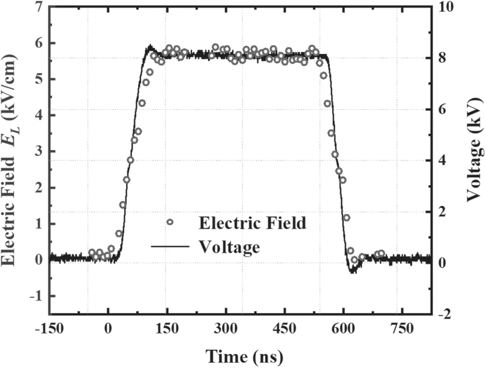
Figure 5.Applied voltage and measured electric field by E-FISH at 5 mm away from the nozzle(z=5 mm)when no plasma is generated.The applied voltage is 8 kV,pulsed frequency is 5 kHz and pulse width is 500 ns.
Helium or helium mixed with a small amount of oxygen or nitrogen is used as the working gas.The total gas flow rate is 2 l min−1.A schematic of the plasma jet device is shown in figure 2.The high-voltage electrode is made of a tungsten needle,which is placed in a glass tube.The tip of the tungsten needle is 5 mm away from the nozzle of the glass tube.The inner diameter of the glass tube is 5 mm,the inner diameter of the nozzle is 1 mm,and there is no extra electrical ground during the measurements.The position of the nozzle is labelled asz=0 mm.The high-voltage electrode is connected to a nanosecond pulsed high-voltage power supply with peak voltage up to 10 kV,frequency up to 10 kHz,and pulse width adjustable from 200 ns to DC.The voltage is measured by a voltage probe(Tektronix P6015)and recorded by an oscilloscope(Tektronix DPO7104).The dynamics of the plasma are captured by an ICCD camera(Andor DH-334).The plasma jet device is placed on a movable station adjusted by a micrometer to change the laser focusing position.The time-resolved electric field of the plasma can be obtained by changing the delay time of the power supply,the laser and the ICCD camera through the digital delay generator(DG645).
The E-FISH signal intensity is related to several factors,including the electric field,fundamental frequency laser intensity,interaction length between laser and the electric field,particle number density,etc.Therefore,the system needs to be calibrated to establish the relationship between the E-FISH signal and the electric field.During the calibration,the factors affecting the E-FISH signal intensity should be kept the same as the measurement conditions.
3.Experiment results
To calibrate the E-FISH system,two parallel plate electrodes with a diameter of 3 cm are used.In order to avoid the influence of different gases on the third-order nonlinear polarizabilitythe plate electrodes are placed in a chamber filled with helium at atmospheric pressure.The gap distance between the two plate electrodes is fixed at 1 cm.The laser passes through the center of the two plate electrodes.Different voltages(2–10 kV)are applied to the two electrodes,the corresponding E-FISH signals are measured and the calibration curve is obtained as shown in figure 3(a).The electric field and the square root of the E-FISH signal are shown in figure 3(b),which has a good linear relationship.According to figure 3(b),the slope of the line is the calibration coefficientAof equation(6),which is about 5.624.Then,the equation(6)can be expressed as:
However,the different working gases or electrode structures have an effect on generation of E-FISH;further calibration is needed[33].In figure 4(a),when the applied voltage is 8 kV and no plasma is generated,the electric field at 5 mm away from the nozzle(z=5 mm)of the plasma jet device is simulated by COMSOL.Then,we obtain the electric field gradient by setting different voltages and the corresponding E-FISH signal is measured.The calibration result is shown in figure 4(b);it can be found that mixing with oxygen has some influence on the intensity of E-FISH,but it still has a good linearity between the electric field and square of E-FISH,and the slope of the line indicates the calibration coefficientAin different situations.Note that when pure He is used for calibration,the calibration coefficient of jetA′=5.903 is very close to that of parallel plateA=5.624,which indicates that only negligible air is mixed into the interaction length.
In the next part,the temporal electric field at 5 mm away from the nozzle(z=5 mm)of the plasma jet device is measured when no plasma is generated.It can be seen from figure 5 that the waveform of the electric field has a similar shape to the applied voltage,which indicates that the measurement of the electric field has a good time resolution.Meanwhile,according to figure 4(a),when the applied voltage is 8 kV,the electric field is about 6 kV cm−1at 5 mm away from the nozzle(z=5 mm),and the calibration results are consistent with the simulation results.Note that the E-FISH signal after calibration obtains a line-integrated electric field along the laser path,and we useELto indicate the line-integrated electric field.
Then,helium(99.999%)flows through the plasma jet device with a gas flow rate of 2 l min−1.It can be seen from figure 6 that the plasma propagates out of the nozzle at 60 ns,reaches the laser position at 90 ns,and the plasma bullet keeps propagating,leaving a dark channel behind after 130 ns.After 1000 ns,the falling edge of the applied voltage appears and a secondary discharge is ignited.At about 1085 ns,the plasma reaches the laser position.Then,the luminous region becomes weaker and eventually disappears.
Furthermore,the electric field at the position of 1 cm away from the nozzle(z=1 cm)is measured.The exposure time of the ICCD is set at 10 ns,which is slightly larger than the laser pulse width of 8 ns.Figure 7 shows the electric field obtained through the E-FISH method.It is shown that the electric field reaches its peak of about 25 kV cm−1att1=85 ns.Then the plasma keeps propagating and the electric field atz=1 cm decreases gradually to 5 kV cm−1at about 450 ns and stays at about 5 kV cm−1until the falling edge of the voltage pulse at 1000 ns.Then the electric field drops quickly and increases reversely to a peak of−14 kV cm−1att2=1085 ns.The results of electric field measurement are consistent with the dynamics of the plasma bullet.For a given position,the electric field is the highest at the moment when the head of the plasma bullet reaches the position.With the propagation of the plasma bullet,a dark channel appears;the electric field in the dark channel is about 5 kV cm−1.Note that the E-FISH method only obtains the intensity of the electric field;the polarity of the electric field needs additional judgment.According to the measured results and the dynamics of the plasma,there is no sudden change in electric field.Therefore,we define the positive direction of thez-axis as the positive polarity of the electric field;when the electric field drops to zero,the polarity of electric field changes to negative polarity.
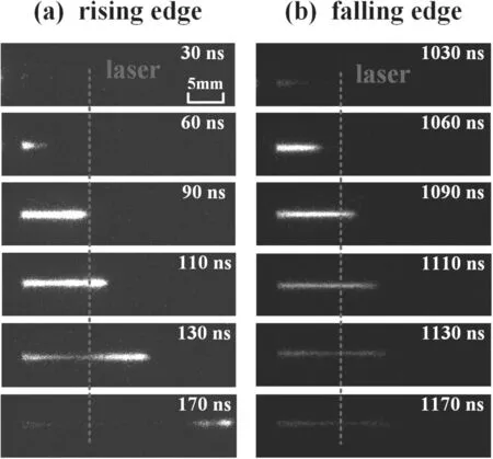
Figure 6.Dynamics of the plasma jet at the(a)rising edge and(b)falling edge of the applied voltage.The dotted red line indicates the position where the laser passes through(z=1 cm).The applied voltage is 8 kV,pulse repetition rate is 5 kHz,pulse width is 1 μs,helium flow rate is 2 l min−1 and exposure time of the ICCD camera is 5 ns.
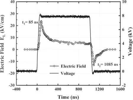
Figure 7.Time-resolved electric field at 1 cm away from the nozzle(z=1 cm)obtained by E-FISH method. t1 and t2 indicate the moments of the electric field reaching its positive and negative peaks,respectively.The applied voltage is 8 kV,pulse repetition rate is 5 kHz,pulse width is 1 μs and pulse rising time is 60 ns.
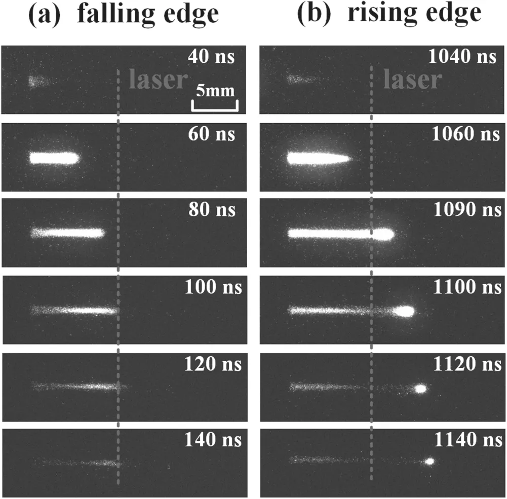
Figure 8.Dynamics of the plasma bullet behavior at the(a)falling edge and(b)rising edge of the negative voltage pulse.Applied voltage is −8 kV,pulse repetition rate is 5 kHz,pulse width is 1 μs,helium gas flow rate is 2 l min−1 and exposure time of the ICCD camera is 5 ns.The dotted line indicates where the laser passes through(z=1 cm).
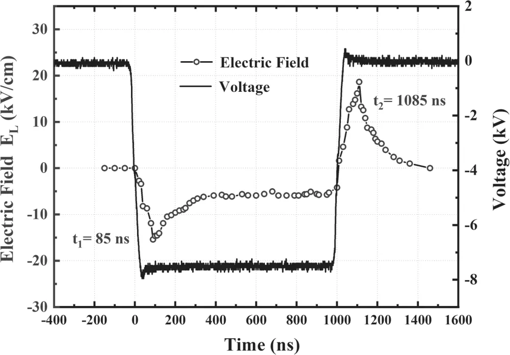
Figure 9.Time-resolved electric field at 1 cm away from the nozzle(z=1 cm)obtained by E-FISH method. t1 and t2 indicate the moments of the electric field reaching its negative and positive peaks respectively.Applied voltage is −8 kV,pulse repetition rate is 5 kHz and pulse width is 1 μs.
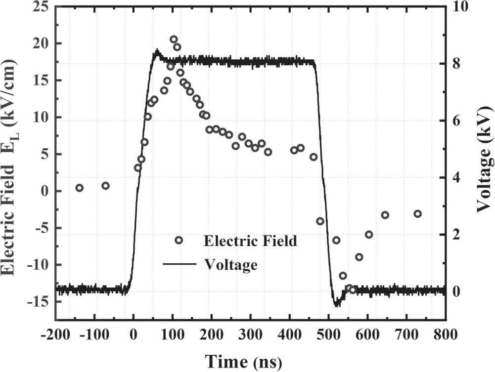
Figure 10.Time-resolved electric field at 1 cm away from the nozzle(z=1 cm)obtained by E-FISH method.Applied voltage is 8 kV,pulse repetition rate is 5 kHz,pulse width is 500 ns and pulse rising time is 60 ns.
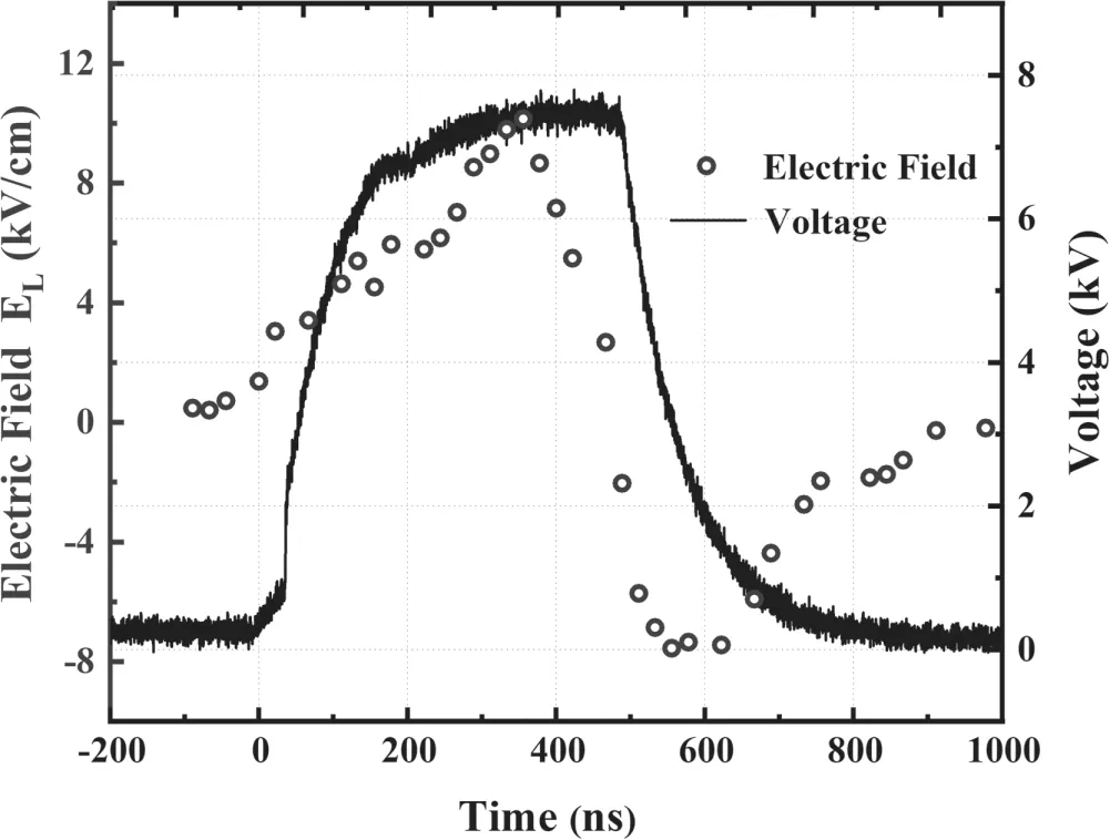
Figure 11.Time-resolved electric field at 1 cm away from the nozzle(z=1 cm)obtained by E-FISH method.Applied voltage is 8 kV,pulse repetition rate is 5 kHz,pulse width is 500 ns and pulse rising time is 200 ns.
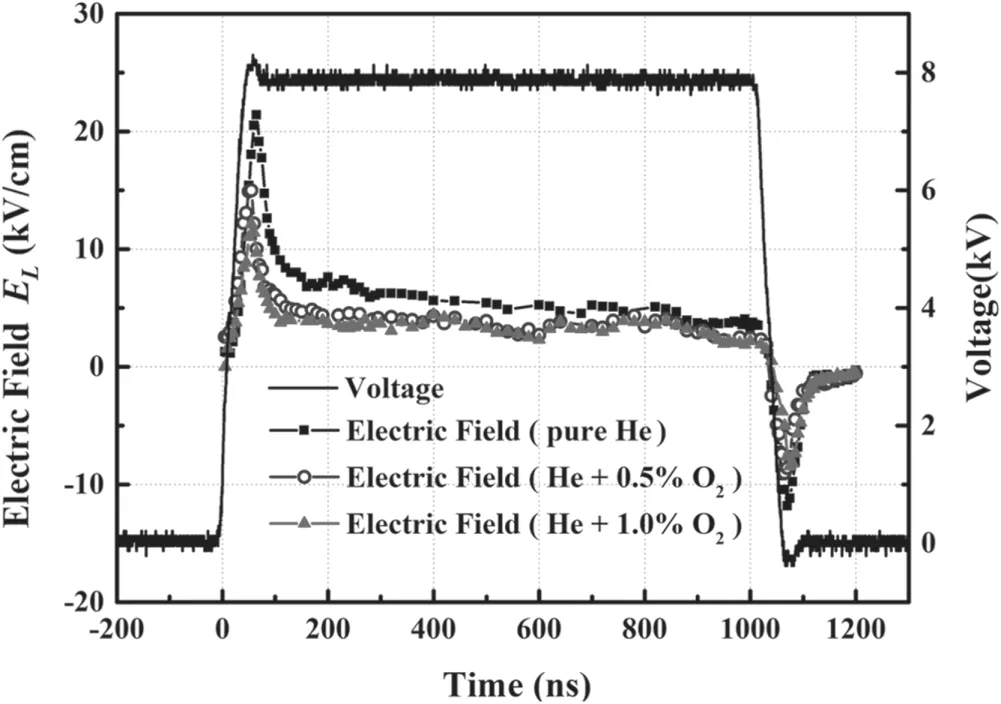
Figure 12.Time-resolved electric field at 5 mm away from the nozzle(z=5 mm)obtained by E-FISH method when different amounts of oxygen are added to the working gas.Applied voltage is 8 kV,pulse repetition rate is 5 kHz,pulse width is 500 ns and pulse rising time is 60 ns.
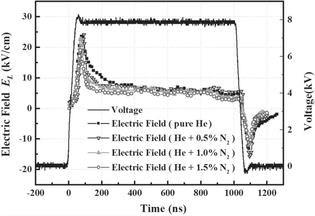
Figure 13.Time-resolved electric field at 5 mm away from the nozzle(z=5 mm)obtained by E-FISH method when different amount of nitrogen is added to the working gas.Applied voltage is 8 kV,pulse repetition rate is 5 kHz,pulse width is 500 ns and pulse rising time is 60 ns.
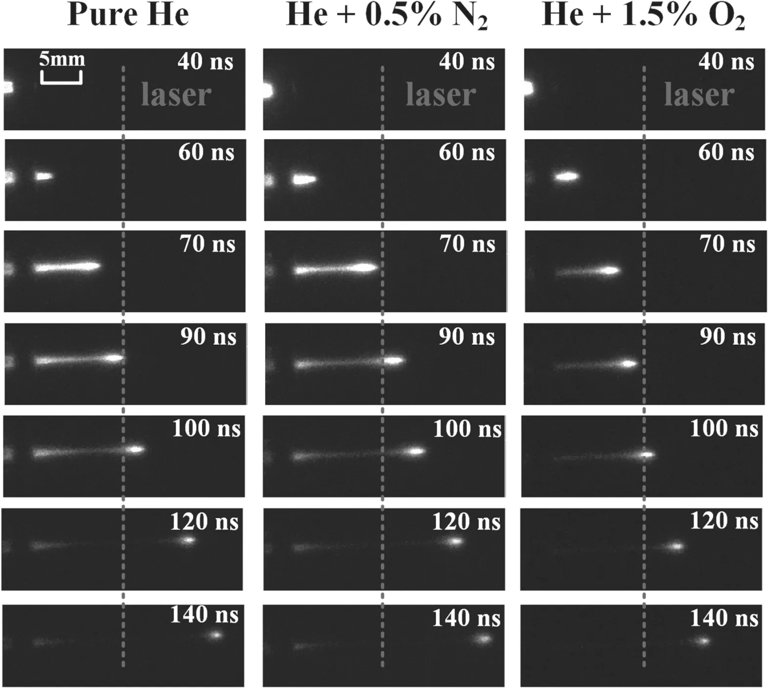
Figure 14.Dynamics of the plasma jet for working gas of He,He+0.5%N2,and He+1.5%O2.The dotted red line indicates the position of 1.5 cm away from the nozzle(z=1.5 cm).The applied voltage is 8 kV,pulse repetition rate is 5 kHz,pulse width is 1 μs,total gas flow rate is 2 l min−1 and exposure time of the ICCD camera is 5 ns.
As we know,the polarity of the applied voltage affects the dynamics of the APPJs,which is related to the difference in the electric field of the plasma channel[34–37].In the next part,a negative polarity of the nanosecond pulsed power supply is used.The applied voltage is adjusted to −8 kV.All of the other parameters are the same as above,i.e.the pulse repetition rate is fixed at 5 kHz,and the pulse width is 1 μs.The dynamics of the plasma bullet behavior are captured by the ICCD camera,as shown in figure 8.When the applied voltage changes from 0 to −8 kV,the plasma propagates with a long tail.The maximum propagation distance of the plasma during the increase in the voltage is shorter than the case of 8 kV.On the other hand,the propagation of the plasma is more like a plasma bullet at the rising edge of the applied voltage.
For the applied voltage of −8 kV,the time-resolved electric field at 1 cm away from the nozzle(z=1 cm)obtained by E-FISH method is shown in figure 9.The electric field increases quickly when the applied voltage changed from 0 to −8 kV.The electric field reaches its peak of−16 kV cm−1att1=85 ns.Then it decreases slowly to about−6 kV cm−1and stays as a constant until 1000 ns.Afterwards,with the drop of the applied voltage from −8 kV to zero,the electric field quickly increases to a peak of about 20 kV cm−1.Subsequently it decreases to zero after about 500 ns.It is worthy to point out that the peak electric field att2during the secondary discharge is significantly higher than that att1during the first discharge.
According to figures 7 and 9,it is found that the peak electric field is about 20–25 kV cm−1at the edge when the applied voltage changes from 0 to 8 kV or −8 to 0 kV.In addition,the plasma appears like a bullet during these periods.On the other hand,at the edge when the applied voltage changes from 8 to 0 kV or 0 to −8 kV,the peak electric field is about −14 to −16 kV cm−1.The plasma propagates much shorter distance and it has a relatively bright long tail.
In the next part,the effects of the pulse width and the pulse rising time on the electric field of the plasma bullet are measured.Firstly,the pulse width is reduced to 500 ns.All of the other parameters remain unchanged.The applied voltage waveform along with the measured electric field is shown in figure 10,which is similar to the results shown in figure 7.It reaches a peak value of about 21 kV cm−1at 85 ns,and there is also a secondary discharge at the falling edge with a peak value of about −15 kV cm−1.
Secondly,the pulse rising time is increased from 60 to 200 ns.The applied voltage waveform and the obtained electric field at 1 cm away from the nozzle(z=1 cm)by E-FISH method are shown in figure 11.It can be seen that the electric field increases slowly and reaches a peak of about 10.5 kV cm−1at about 350 ns,which is much weaker than the case of 60 ns pulse rising time.Accordingly,the electric field induced by the secondary discharge at the falling edge is also much weaker,which is about −8 kV cm−1.Compared to the rapid falling edge of the voltage,the longer falling time makes discharge occur in the process of the voltage drop.This phenomenon also happens at the rising edge of the voltage.However,in figure 11,due to the imperfect rising edge of the voltage,the voltage still slowly rises after 200 ns,which causes the time of the electric field reaching its peak to be delayed to about 350 ns.
When APPJs are used for various applications,a trace amount of nitrogen or oxygen is often added to the working gas,which can increase the concentration of reactive nitrogen species(RNS)or reactive oxygen species(ROS)[38–41].However,how the trace amount of nitrogen or oxygen affects the electric field and thus the propagation of the plasma jets has not been investigated.Note that the hyperpolarizability between helium and oxygen(or nitrogen)is significantly different;only a tiny amount of oxygen or nitrogen can be mixed into helium in this experiment.Moreover,in order to reduce the mixing of ambient air,sufficient helium flow rate is required and the measurement position should be close to the nozzle.Corresponding calibration is carried out under the same experimental conditions,which can be found in figure 4.Although the hyperpolarizability of argon is much closer to that of air,the helium jets are more widely used in applications,and the propagation of the helium plasma is like a bullet but that of argon plasma is like filaments;a more regular shape is convenient for simulation and correction[42].
Firstly,0%,0.5% and 1.0% oxygen are added into helium with a total gas flow rate of 2 l min−1.All the other parameters are kept the same.The electric field at 5 mm away from the nozzle(z=5 mm)is measured by the E-FISH method as shown in figure 12.It is clearly shown that,when 0.5% of oxygen is added,the peak electric field at the rising edge reduced from 22 to 15 kV cm−1.Moreover,the electric field decreases much faster and it stays at a value of about 2 kV cm−1lower than in the case of pure helium before the falling edge of the applied voltage.When 1% of oxygen is added,the peak electric field becomes even weaker.
Secondly,0%,0.5%,1.0% and 1.5% nitrogen are added to the working gas and the corresponding electric field is measured by the E-FISH method as shown in figure 13.It can be seen that,when 0.5% nitrogen is added,the peak electric field actually slightly increases,especially at the falling edge of the voltage pulse,and it increases reversely from −12 to−16 kV cm−1.However,when 1.5% nitrogen is added,the peak electric field decreases from 24 to 19 kV cm−1at the rising edge of the voltage pulse.Moreover,it is found that the electric field decreases much faster when a trace amount of nitrogen is added compared with the pure helium case.
We know that the higher the electric field is,the faster the plasma bullet propagates.To see if this is true,high-speed photographs of the plasma for He only,He+0.5%N2,and He+1.5%O2are captured by an ICCD camera with exposure time of 5 ns.The obtained results are shown in figure 14.For the case of He only,the plasma already reaches 1.5 cm(red dotted line)out of the nozzle at 90 ns.For the case of He+0.5%N2,the plasma propagates faster and reaches 1.5 cm at about 70 ns.When the working gas is changed to He+1.5%O2,it does not reach 1.5 cm at 90 ns and it propagates even more slowly later.
4.Discussion and conclusion
In this work,the electric field induced second harmonic(E-FISH)method is applied to diagnose the electric field of a helium plasma jet.Time-resolved electric fields under different conditions are investigated,including the effects of the applied voltage polarity,voltage pulse rising time and working gases percentage on the electric field of the plasma jet and its dark channel.
When positive pulse voltage is applied,the electric field has a peak of about 25 kV cm−1at the rising edge of the voltage pulse.A dark channel is left behind the plasma bullet and the electric field in the dark channel is about 5 kV cm−1.At the falling edge of the voltage pulse,the electric field increases reversely to a peak of −14 kV cm−1.On the other hand,when negative pulse voltage is applied,the electric field has a peak of −16 kV cm−1when the voltage is increased to−8 kV.A relatively bright channel is left behind the plasma head and the electric field in this relatively bright channel is about −6 kV cm−1.When the applied voltage changed from−8 kV to zero,the electric field reaches a peak of about 20 kV cm−1,which is higher than that of the primary discharge.It is worth emphasizing that the electric field in the dark channel when positive voltage pulse is used is lower than that in the relatively bright channel when negative voltage pulse is used,which is the reason why one is dark and the other one is relatively bright.Because low electric field indicates low electron temperature,a high-energy electron is not enough to excite adequate species,which leads to a relatively dark channel.
When the pulse width is reduced from 1 μs to 500 ns,it does not affect the peak electric field of the plasma bullet.On the other hand,when the pulse rising time increases from 60 to 200 ns,the peak electric fields at both the rising edge and the falling edge of the voltage decrease significantly to about 10.5 kV cm−1and −8 kV cm−1,respectively.
The percentage of gas mixture also affects the electric field of the plasma bullet.When 0.5% of oxygen is added to the main working gas helium,the peak electric field at the rising edge is only about 15 kV cm−1.Moreover,the electric field decreases much faster and stays at a value of about 2 kV cm−1lower than the case of pure helium before the falling edge of the applied voltage.On the other hand,when 0.5% nitrogen is added,the peak electric field actually increases,especially at the falling edge of the voltage pulse,where it increases reversely from −12 to −16 kV cm−1.However,when 1.5%nitrogen is added,the peak electric field decreases from 24 to 19 kV cm−1at the rising edge of the voltage pulse.Note that the influence of the temporal electric field profile is not considered in this work;more modification can be carried out for future diagnostics[42].
Acknowledgments
This work was supported by National Key Research and Development Program of China(No.2021YFE0114700)and National Natural Science Foundation of China(Nos.52130701 and 51977096).
猜你喜欢
Plasma Science and Technology(2022年5期)2022-06-01
Plasma Science and Technology(2021年6期)2021-06-21
戏剧之家(2019年4期)2019-03-28
小学生学习指导(低年级)(2017年12期)2017-11-22
小说林(2017年6期)2017-11-08
今古传奇·故事版(2017年8期)2017-05-19
故事作文·低年级(2009年9期)2009-12-10
故事作文·低年级(2009年8期)2009-11-25
故事作文·低年级(2009年7期)2009-11-23
 Plasma Science and Technology2023年1期
- Plasma Science and Technology的其它文章
- Development of miniaturized SAF-LIBS with high repetition rate acousto-optic gating for quantitative analysis
- Rotor performance enhancement by alternating current dielectric barrier discharge plasma actuation
- A nanoparticle formation model considering layered motion based on an electrical explosion experiment with Al wires
- Focused electron beam transport through a long narrow metal tube at elevated pressures in the forevacuum range
- A study of the influence of different grid structures on plasma characteristics in the discharge chamber of an ion thruster
- High-resolution x-ray monochromatic imaging for laser plasma diagnostics based on toroidal crystal