
Focused electron beam transport through a long narrow metal tube at elevated pressures in the forevacuum range
2023-03-09 05:45IlyaBAKEEVKirillKARPOVAleksandrKLIMOVEfimOKSandAlekseyZENIN
Plasma Science and Technology 2023年1期
Ilya BAKEEV,Kirill KARPOV,Aleksandr KLIMOV,Efim OKS,2 and Aleksey ZENIN
1 Tomsk State University of Control Systems and Radioelectronics,Tomskaâ 634050,Russia
2 Institute of High Current Electronics,Siberian Branch,Russian Academy of Sciences,Tomskaâ 634055,Russia
Abstract We present here our investigations of the features of focused electron beam transport in free space at elevated pressures of a few pascals.We have explored the effect of the beam accelerating voltage,operating gas pressure,and magnetic focusing upon the trajectory of beam electrons in the crossover region,in particular on the beam convergence and divergence angles.It is shown that for the forevacuum pressure range of 2–5 Pa explored,a distinctive feature of the propagation of a focused electron beam with a current of up to 20 mA at an accelerating voltage of 10–20 kV is the difference in the angles of convergence(before the focus)and divergence(after the focus).Whereas at a low pressure of 2 Pa the divergence angle is smaller than the convergence angle,as the pressure increases the divergence angle increases and for pressures greater than 5 Pa the divergence angle is greater than the convergence angle.The results obtained were used in experiments on electron beam transport through a long narrow metal tube with a diameter of 5.8–9.2 mm and length of 10–30 cm.We show that for a 30 cm long tube of 7.5 mm diameter,the focused beam transmission can exceed 70%.
Keywords:focused electron beam,plasma electron source,forevacuum pressure range,long metal tube
1.Introduction
Ion-plasma processing methods find application in material surface cleaning,coating deposition,and surface modification of metal and dielectric materials for various purposes[1–3].For example,ion-plasma nitriding is a well-established industrial process for surface hardening,producing surfaces that have high wear resistance,and fatigue and corrosion resistance for a wide range of metals and alloys[4,5].Many different gas-discharge systems have been developed in recent years for generating the low-temperature plasma used for surface processing.These systems differ in their operating gas pressure and processing regime(continuous or high frequency),as well as in the means employed for plasma generation and heating[6–9].Most of these systems,however,are appropriate for the modification of external surfaces only.
Ion-plasma treatment of the inner surfaces of narrow tubes with transverse dimensions of a few millimeters necessitates addressing the challenge of plasma penetration into the tube and the issue of plasma uniformity along its length.These two problems are yet further complicated because a gas discharge plasma generated outside the tube is separated from it by a space charge layer,since the tube is typically held at negative potential relative to the plasma[10].For these reasons,filling a long narrow tube with plasma that is uniform over the entire length is possible only by additional gas ionization inside the tube.Several different methods have been used to achieve this goal.One approach is to install auxiliary electrodes inside the tube for plasma production[11,12].An obvious shortcoming of this approach is the limitation of the minimum diameter of the workpiece to a few centimeters,due to the need for installing and positioning the electrodes themselves.
Use of an anomalous glow discharge[13,14]at high operating gas pressure(a few hundred pascals)provides another approach,and for a metal cavity,plasma production is enhanced by the hollow cathode effect.In one application of this approach[14],the minimum diameter of the cavity used was limited to 6 mm and to aspect ratio(ratio of cavity length to diameter)less than 50.At a high pressure of a few hundred pascals,however,the high ion-neutral collision frequency results in plasma ions reaching the tube(or cavity)surface with energies of only a few tens of eV,regardless of the applied plasma potential.These low-energy ions have very low etching capability,which,for the case of ion-plasma nitriding,does not allow the surface to be cleaned of its surface oxide layer that prevents the penetration of nitrogen deep into the metal.
A more efficient approach to ion-plasma treatment inside a tube or cavity utilizes a low-pressure discharge(less than 1 Pa)formed within the tube[15,16].The improved efficiency of this kind of system is related to the passage of ions through the near-cathode sheath with low collision probability because of the low pressure,and hence the availability of high energy ions.Also,in plasma nitriding there is an increased efficiency of surface saturation with nitrogen compared to the higher pressure situation,due to more intense production of active atomic nitrogen in the low-pressure discharge near the processed surface.A strategy has been demonstrated[10]in which a long tube is filled with plasma at low pressure by igniting a non-self-sustained discharge with the tube used as a hollow cathode and with electron injection into the cavity from an auxiliary plasma generator;the inner surfaces of AISI 321 steel tubes with inner diameter of 25 mm and length of 300 mm were in this way nitrided.
The advantages of low pressure ion-plasma treatment for smaller diameter tubes and higher gas pressure than in[10]can be preserved by injecting a focused electron beam into the tube.This can be achieved by using a forevacuum-pressure plasma-cathode electron source[17,18].These sources generate electron beams at elevated pressures of a few to a few tens of pascals,in which the pressure range the operating gas is effectively ionized by energetic electrons.It is possible to focus the electron beam to a focal spot,or crossover,with diameter less than 1 mm,convergence angle 0.1°,and power density at crossover of up to 106W cm−2,despite the scattering of beam electrons by gas molecules[18–20].The electron beam generated by a forevacuum plasma source can be used to form an auxiliary glow discharge in a long narrow metal tube for ion-plasma modification of its inner surface.In this case,the high current density of the focused electron beam provides the conditions for efficient ionization and initiation of a discharge in a tube of diameter several millimeters.Furthermore,the electron beam provides additional control of the discharge distribution in the tube.All previous studies of focused electron beams generated by a forevacuum source have been devoted to measuring the beam parameters at crossover.However,the application of a focused electron beam to transport through a tube requires an understanding of how the beam propagates along its entire path.Here we describe our exploration of some specific features of the propagation of a focused electron beam generated by a forevacuum-pressure plasma-cathode electron source(‘forevacuum plasma electron source’)in long narrow tubes.
2.Experimental setup and technique
A simplified schematic of the experimental setup is shown in figure 1.
Forevacuum plasma electron source(1)of focused electron beam(2)is mounted on a vacuum chamber equipped with a single-stage mechanical BocEdwards pump,which evacuates the chamber to a base pressure of 1 Pa.Nitrogen is then admitted to a working pressurep=2–5 Pa.A detailed description of the forevacuum electron source and its working principles has been presented elsewhere[19,20].The source is based on the emission of electrons from plasma(3),formed by a steady-state hollow-cathode(4)glow discharge through a single emission channel of diameterDemand lengthHemin the center of anode(5);the hollow cathode glow discharge is maintained by power supply(9),with discharge currentId=1 A.Electrons are accelerated by the electric field of the accelerating gap formed by anode(5)and extractor(6);the accelerating voltageUa=10–20 kV.The beam is focused by magnetic lens(7),and steered by magnetic deflection system(8).
The specific design and dimensions of the source,so as to deliver maximum beam brightness,were selected based on prior work[20].In particular,the dimensions of the anode emission channel wereDem=1.2 mm andHem=2 mm.For our experimental parameters and source geometry,the beam current was up toIb=20 mA.
The electron beam diameterdbis measured using the standard ‘deviation’ method[21],whose principle lies in deflecting,or steering,the beam across two extended narrow slits(11)in the upper plate of analyzer(12).The current signal to the collector plate(14)is monitored by an oscilloscope,and transformed to a radial distribution of beam current;the beam diameter is taken as the full width at half maximum(FWHM)of the radial distribution.Details of the beam diameter measuring principle and the conversion algorithm of current signal to radial current density distribution have been described in full elsewhere[18].
The analyzer can be moved along the verticalz-axis(thez-axis and the direction of movement of analyzer(15)are shown in figure 1(a))by a manipulator system installed in the vacuum chamber.The origin of the coordinatezis set at the extractor(6)of the electron beam source.The probe can be moved over a range of 30–60 cm from extractor(6)(limited by the size of the vacuum chamber).The beam is focused by magnetic lens(8)so that the beam focus,or crossover,occurs at the location of the analyzer.
The total electron beam currentIbis measured by deflecting the beam to stand-alone Faraday cup(16).The total beam current and the distribution of diameterdbalong thezcoordinate,db(z),were measured with the beam propagating in free space(figure 1(a)).
Propagation of the focused electron beam in stainless steel metal tube(17)with inner diameterDtand lengthLtwas investigated using the setup shown in figure 1(b).We explored tubes with an inner diameter that varied over the rangeDt=5.8–15 mm and lengthLt=10–30 cm.The metal tube was oriented vertically along the focused beam propagation direction(2).Coaxiality of the electron beam and the tube was attained by shifting the tube horizontally and adjusting the electron beam deflection by deflection system(8).A beam collector,in the form of Faraday cup(16),was placed behind the lower end of the tube.The currentItin tube circuit(17)as well as the currentIcto collector(16)was measured.The tube currentItin this case is determined by the loss of beam electrons to the inner wall and upper(entrance)end of the tube.The total beam currentIbwas determined as the sum of the currents running through the tube and to the collector,Ib=(Ic+It).The relationIb=(Ic+It)was confirmed experimentally by sequential measurements of the currentsIcandItwith the tube and of the currentIb,to collector(16)with the tube removed.The fraction of electron beam current passing through the tube(hereinafter the current transmission coefficientIc/Ib)was determined asIc/(Ic+It).By controlling the magnetic lens current we could ensure focusing conditions that yield a maximum current transmission coefficientIc/Ibfor given electron beam parameters and tube dimensions.
3.Results and discussion
Spatial focusing of the electron beam is characterized by the axial(z)distribution of beam radiusrb(figure 2).
As can be seen,the character of the focused electron beam propagation changes significantly when the beam passes the crossover plane;there is a significant difference between angles of propagation of the focused electron beam to the vertical axisz—the beam convergence angle α and divergence angle β(figure 2).
The beam accelerating voltage(electron energy),gas pressure,and magnetic focusing parameters all have different effects on beam convergence and divergence.Figure 3(a)shows that for pressurep=2.5 Pa,the beam convergence angle α exceeds the divergence angle β for all crossover positionszc.The angles α and β decrease monotonically as the crossover positionzcincreases,but the divergence angle β decreases to a greater extent.At an accelerating voltageUa=10 kV and a crossover distancezc=35 cm,the difference between the angles α and β is less than 20%(figure 3(a),graph 1).For greater distanceszc,the difference between these angles grows considerably,and forzc=55 cm the convergence angle α exceeds the divergence angle β by a factor of 4.At high beam accelerating voltageUa=20 kV(figure 3(a),graph 2),the behaviors of the α(zc)and β(zc)dependencies are preserved.Increasing the accelerating voltage in this case decreases the angles α and β and decreases the steepness of the dependencies α(zc)and β(zc).In this case,the influence of accelerating voltage on the behavior of the beam propagation angles(before the focus and after the focus)is due to the processes of beam formation in the region of electron emission and acceleration.Thus,at higher accelerating voltage,the initial divergence of the electron beam in the beam acceleration region decreases significantly.This leads to the electron beam having a smaller transverse dimension,and for focusing at the same distance from the magnetic lens,it propagates with a smaller convergence angle.
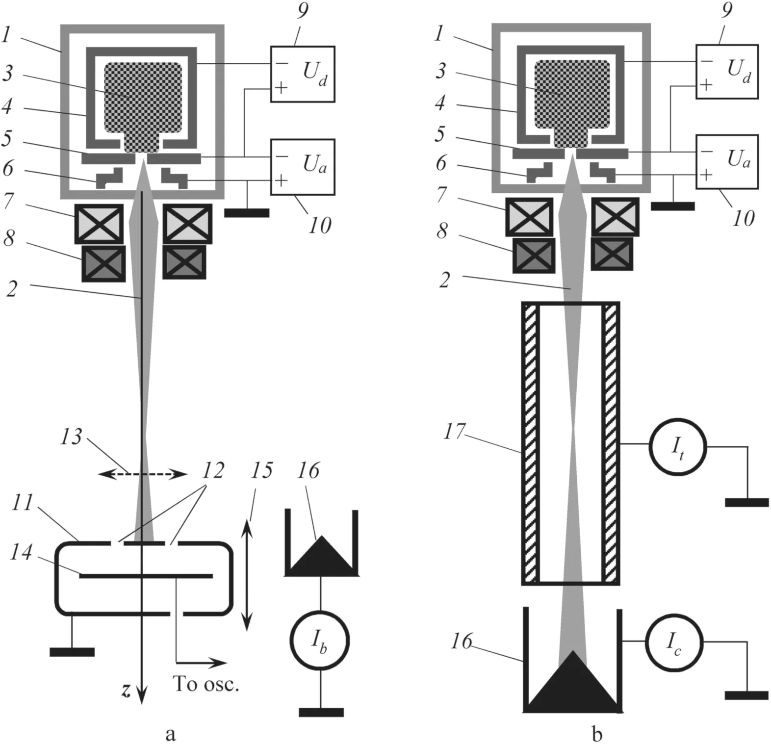
Figure 1.Schematic diagram of the experimental setup and technique,(a)as configured for the measurement of electron beam parameters in free propagation,and(b)as configured for the measurement of beam propagation in the metal tube.(1)forevacuum plasma electron source;(2)focused electron beam;(3)emission plasma;(4)hollow cathode;(5)anode with central emission channel;(6)extractor;(7)magnetic focusing lens;(8)magnetic deflection system;(9)discharge power supply;(10)accelerating voltage source;(11)analyzer slits;(12)analyzer;(13)beam sweep direction for beam diameter measurements;(14)current collector plate;(15)direction of analyzer movements;(16)Faraday cup;(17)metal tube.
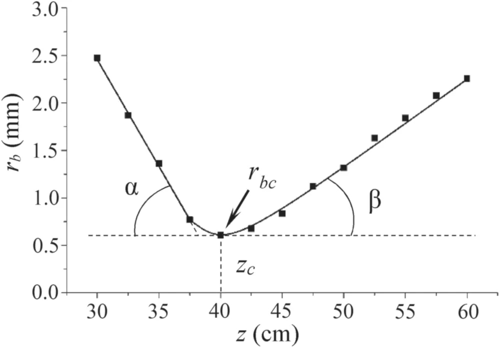
Figure 2.Measured rb(z)distribution is the beam radius versus propagation distance z for focused electron beam.α is the beam convergence angle,β is the beam divergence angle, rbc is the beam radius at crossover and zc is the crossover position.Operating gas pressure p=2.5 Pa,accelerating voltage Ua=10 kV,beam current Ib=20 mA.
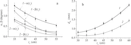
Figure 3.Dependencies of(a)focused beam convergence angle α and divergence angle β,and(b)beam crossover diameter dbc as a function of crossover position zc for different accelerating voltages Ua:1 – Ua=10 kV,2 – Ua=20 kV.Operating gas pressure p=2.5 Pa,beam current Ib=20 mA.
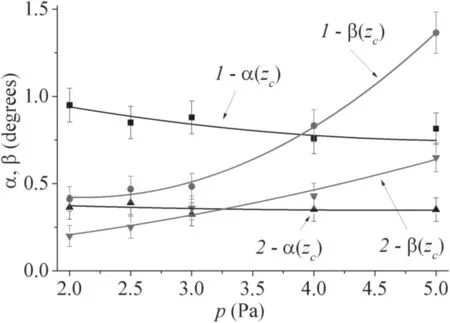
Figure 4.Dependence of the focused beam convergence angle α and divergence angle β on gas(argon)pressure p for different beam accelerating voltages Ua:1 – Ua=10 kV,2 – Ua=20 kV.Beam current Ib=20 mA,beam crossover position zc=45 cm.
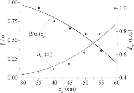
Figure 5.Ratio of divergence angle to convergence angle β/α of the focused electron beam,and beam crossover diameter dbc as a function of crossover position zc.Dots show the experimental data;solid lines show the calculated dependences.Accelerating voltage Ua=20 kV,pressure p=2.5 Pa.

Figure 6.Dependencies of the current transmission coefficient Ic/Ib of the focused electron beam on tube length Lt for different tube diameters Dt:1–Dt=9.2 mm,2–Dt=7.5 mm,3–Dt=5.8 mm.Beam accelerating voltage Ua=20 kV,pressure p=2.5 Pa,beam current Ib=20 mA.
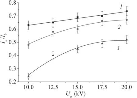
Figure 7.Dependencies of current transmission coefficient Ic/Ib of focused electron beam on accelerating voltage Ua for different operating gas pressures p:1 – p=2.5 Pa,2 – p=3 Pa,3 –p=5 Pa.Beam current Ib=20 mA,tube inner diameter Dt=7.5 mm,tube length Lt=30 cm.
In addition,as the distance from the extractor increases,the beam crossover diameter increases significantly(figure 3(b)).However,greater accelerating voltage(graph 2)results in a smaller beam crossover diameterdbc,and to a smaller growth in the dependencedbc(zc).
Gas pressure is an important factor in the formation and transport of electron beams.As described elsewhere[17],an increase in gas pressure results in the greater scattering of beam electrons on gas molecules,which increases the beam crossover diameter.Our studies have shown that gas pressure also has an effect on the divergence angle β,while the convergence angle does not change significantly(figure 4).Pressure affects the beam divergence angle to a greater degree at lower accelerating voltage(figure 4,graph 1).
Importantly,note that it is at elevated operating gas pressure that the observed difference between the angles α and β manifests itself.Scattering of beam electrons on gas molecules causes a significant broadening of the electron beam energy distribution and increased scatter in the angles of electron propagation when the beam is formed in the accelerating gap.This leads to increased aberration during magnetic focusing of the beam.
To evaluate these processes,numerical modelling of the focused beam transport at elevated pressures was carried out using a model we have developed previously.A detailed description of the model is given in[22].This model allows the calculation of electron trajectories in the beam generated by a forevacuum electron source at elevated pressure,when the beam space charge is compensated by ions from the beam-plasma,but ignition of the beam-plasma discharge does not yet appear.The model electrode geometry for the accelerating gap and focusing lens was taken to be the actual dimensions of our electron source.The electric field in the accelerating gap and the magnetic field of the focusing system were numerically calculated according to the Poisson and Maxwell equations.Electrons initially emitted from the plasma were located in the lower plane of the anode emission channel,and the distribution of initial electron radial velocities was taken to be Maxwellian with electron temperature 1 eV.The scattering of electrons on gas molecules was accounted for using the Rutherford formula.The result of our calculations was a set of trajectories for individual electrons emitted from the emission channel,transported through the accelerating gap,and further focused by the lens magnetic field.Modelling with the three-dimensional electrode geometry and field configuration close to the physical source allows one to take into account spherical and chromatic aberrations typical of magnetic lenses.The radial distribution of electron density as a function of distancezfrom the extractor was constructed from the calculated set of electron trajectories.As in our experiment,the electron beam diameter at cross-over was taken as the width of the electron current density distribution at half height(FWHM).Based on the calculated dependencies of beam radius on the axial coordinate,rb(z),theoretical values of the beam convergence α and divergence β angles and the beam crossover diameterdbcwere determined.
Numerical modelling showed that without accounting for the scattering of electrons on gas molecules,the initial distribution of electron velocities corresponding to their temperature of 1 eV is not sufficient to produce a significant difference between beam convergence and divergence angles.The calculated dependencies of the angle ratio β/α and the beam crossover diameterdbcon crossover positionzcobtained in modelling with beam scattering taken into account are shown in figure 5 together with the experimental data.In this case,the ratio β/α in figure 5 describes the difference between the angle of divergence β and the angle of convergence α.
The experimental and calculated dependencies are in good agreement,indicating that the key factor that causes the difference between beam convergence and divergence angles near the crossover is spherical aberration during magnetic focusing.Longitudinal spherical aberration is known to be greater the further the focal plane is from the focusing lens[23].Thus,the closer the crossover to the focusing lens,the smaller the spherical aberrations;or the closer the foci of all electrons so that the angle ratio β/α is close to 1,and the beam crossover diameter has a minimal value.The longitudinal spherical aberration increases with increasing distance from the lens to the focal plane.Electron trajectories near the lens periphery begin to converge before the crossover plane.Having passed the crossover plane,these electrons diverge at significant radial distances from the beam axis.Thus,after the beam passes the crossover plane,the main contribution to beam current density is from electrons propagating closer to the axis,i.e.,at smaller angles to the axis,which is the cause of the decrease in beam divergence angle compared to convergence angle.Increase inzcalso leads to an increase in transverse spherical aberration,i.e.,the transverse size of the intersection at the narrowest part of the beam also increases due to the foci separation of electrons entering the focusing lens at different distances from its axis.Shown in figure 4,the increase in angle of divergence of the beam is apparently associated with increase in the intensity of electron scattering on gas molecules during beam propagation.The initial excess of the angle of convergence over the angle of divergence(β/α<1)for pressurep=2.5 Pa,as confirmed by calculations,changes to the opposite ratio(β/α>1)as the pressure increases(figure 4),because the electron scattering increases with pressure,causing them to be deflected through large angles.
The characteristics of the focused electron beam propagating in free space allow one to predict conditions that provide propagation of the beam in a long tube with minimal loss to the tube wall.Minimum transverse size of the focused beam over the entire length of the tube will be achieved at minimum beam propagation angle.This is expected to occur at maximum accelerating voltage and minimum working gas pressure(figure 4).Note that to ensure passage of the beam with minimal loss through the tube,one should take into account the difference in the convergence and divergence angles when selecting the crossover position.Due to the difference in these angles,minimum beam loss inside the tube is obtained at a crossover position closer to the tube entrance for pressurep=2.5 Pa(this is most clearly seen at the lower accelerating voltage of 10 kV in figure 2).The lower the accelerating voltage,and accordingly the greater difference in angles(figure 3(a)),the closer to the tube entrance the beam crossover plane is located.On the other hand,as can be seen from figure 4,due to the scattering of electrons on the working gas with increasing pressure,the ratio between the angles of convergence and divergence changes from β/α<1 to β/α>1.All of these factors must be taken into account when a focused electron beam is transported through a narrow extended tube.
The fraction of total beam current that is transmitted through a long narrow tube—the current transmission coefficientIc/Ib—for different tube lengths and diameters is shown in figure 6.For all further results,the position of the electron beam crossover plane in the tube was chosen so as to maximize beam transmission through the tube.
As expected,the beam loss increases monotonically with tube length and with decrease in diameter.The rate of decrease in the dependenceIc/Ib(Lt)decreases for the largest tube diameter(figure 6,graph 1).To generate a uniform plasma over the entire length of the tube,minimal beam loss during propagation through the cavity is needed.Thus,for the beam parameters and gas pressure of figure 6,the minimal diameter of a tube of length 30 cm for which beam loss is acceptable(current transmission coefficient more than 70%)isDt=7.5 mm(figure 6,graph 2).ForDt=5.8 mm(figure 6,graph 3)for long tubes,the current transmission coefficient falls to less than 50%.
Figure 7 shows the effect of beam accelerating voltage and gas pressure on beam transmission through a tube of diameterDt=7.5 mm and lengthLt=30 cm.As can be seen,decrease in accelerating voltage leads to decrease in the current transmission coefficient.However,while at low operating gas pressurep=2.5 Pa(figure 7,graph 1)the decrease is about 10%,beam losses increase considerably for greater pressures(graphs 2 and 3).These results fully agree with the beam convergence angle dependencies shown in figure 3,since the decrease in current transmission coefficient is directly caused by increase in focused beam propagation angle with decreasing accelerating voltage.The effect of pressure in this case is related to the increase in crossover beam diameter and beam divergence angle(figure 4).The character of the effect of accelerating voltage and operating gas pressure on the current transmission coefficient of the focused beam remains valid for all tube sizes shown in figure 6.The greater the current transmission coefficient in figure 6,the less prominent is the effect of decrease in current transmission with change in accelerating voltage and pressure shown in figure 7.
4.Conclusion
We have explored some specific features of focused electron beam transport in free space at elevated pressures,namely the effects of beam accelerating voltage,operating gas pressure,and magnetic focusing on the propagation of accelerated electrons in the crossover region,in particular,on the electron beam convergence and divergence angles.For pressures in the forevacuum range of 2–5 Pa,a distinctive feature of the propagation of a focused beam with a current of up to 20 mA at an accelerating voltage of 10–20 kV is the difference in the angles of convergence(pre-focus)and divergence(postfocus).Whereas for a low pressure of 2 Pa the divergence angle is smaller than the convergence angle,as the pressure increases,the divergence angle increases,and for pressure greater than 5 Pa the divergence angle is greater than the convergence angle.The reason for the smaller value of divergence angle compared to convergence angle is spherical aberration in the magnetic focusing of the beam,as is confirmed by calculation estimates.The reason for the increase in beam divergence angle with increasing pressure is the increased scattering of beam electrons from gas molecules.These results were used in our experiments on electron beam transport through a long narrow metal tubes with diameter 5.8–9.2 mm and length 10–30 cm.The beam loss in the tube increases for longer and narrower tubes,as well as with decreasing accelerating voltage and increasing gas pressure.We show that for a 30 cm long tube of 7.5 mm diameter,the focused beam current transmission can exceed 70%.These results serve as a basis for using electron beams to generate dense uniform plasma in elongated cavities and for the ionplasma modification of internal surfaces of tubular products.
Acknowledgments
These studies were supported by the Russian Science Foundation(No.21-79-10217),https://rscf.ru/project/21-79-10217/.Special thanks to Dr Ian Brown(Berkeley Lab)for English corrections and helpful discussion.
ORCID iDs
 Plasma Science and Technology2023年1期
- Plasma Science and Technology的其它文章
- Development of miniaturized SAF-LIBS with high repetition rate acousto-optic gating for quantitative analysis
- Improving plasma sterilization by constructing a plasma photocatalytic system with a needle array corona discharge and Au plasmonic nanocatalyst
- Rotor performance enhancement by alternating current dielectric barrier discharge plasma actuation
- A nanoparticle formation model considering layered motion based on an electrical explosion experiment with Al wires
- A study of the influence of different grid structures on plasma characteristics in the discharge chamber of an ion thruster
- High-resolution x-ray monochromatic imaging for laser plasma diagnostics based on toroidal crystal