
Underconstrained Cable-Driven Parallel Suspension System of Virtual Flight Test Model in Wind Tunnel
2023-03-12 09:00HuisongWuKaichunZengLiYuYanLiandXipingKou
Huisong Wu,Kaichun Zeng,Li Yu,Yan Li and Xiping Kou
Institute of High Speed Aerodynamics,China Aerodynamics Research and Development Center,Mianyang,621000,China
ABSTRACT An underconstrained cable-driven parallel robot (CDPR) suspension system was designed for a virtual flight testing (VFT) model.This mechanism includes two identical upper and lower kinematic chains, each of which comprises a cylindrical pair,rotating pair,and cable parallelogram.The model is pulled via two cables at the top and bottom and fixed by a yaw turntable, which can realize free coupling and decoupling with three rotational degrees of freedom of the model.First, the underconstrained CDPR suspension system of the VFT model was designed according to the mechanics theory,the degrees of freedom were verified,and the support platform was optimized to realize the coincidence between the model’s center of mass and the rotation center of the mechanism during the motion to ensure the stability of the support system.Finally, kinematic and dynamical modeling of the underconstrained CDPR suspension system was conducted; the system stiffness and stability criteria were deduced.Thus, the modeling of an underconstrained, reconfigurable, passively driven CDPR was understood comprehensively.Furthermore,dynamic simulations and experiments were used to verify that the proposed system meets the support requirements of the wind tunnel-based VFT model.This study serves as the foundation for subsequent wind tunnel test research on identifying the aerodynamic parameters of aircraftmodels, and also provides new avenues for the development of novel support methods for the wind tunnel test model.
KEYWORDS Virtual flight;underconstrained cable-driven; dynamic modeling;stiffness and stability;simulation analysis and experiment
1 Introduction
Wind tunnel-based virtual flight testing (WTB-VFT) was recently developed to combine traditional wind tunnel testing and flight testing[1].In this technology,a support device is used to support the model in the wind tunnel test section for blowing testing, the three linear displacements of the model are constrained, and the three rotational angular displacements of the model are provided.The flight control law was designed based on the simulation similarity criterion.Control surfaces can be manipulated to control the model deflection and to examine the maneuvering response characteristics, from which the aerodynamic-motion coupling mechanism [2] can be studied and an integrated aerodynamic-motion control testing platform can be established.However, the support device must meet the requirements of a large corner range and small support interference, as well as perform the function of free coupling and decoupling with three rotational degrees of freedom.
Therefore,scholars from several countries have conducted various studies on VFT in wind tunnels.To understand the pitch, roll, and yaw motions of a missile, Gebert et al.[3–5] in the United States performed VFT using multiple steel cables to suspend and support a missile model in a wind tunnel through the external bearing ring of the model.
Lowenberg et al.[6] designed a pendulum-type support mechanism to investigate the passivedriven motion of the vehicle,including the single degree of freedom of pitch and two degrees of freedom of pitch and lift;Davison[7]and Gatto et al.[8]designed a rigid support mechanism with three degrees of freedom,and performed system modeling and stability derivative tests;Pattinson et al.[9]realized a support mechanism with five degrees of freedom,performed dynamic modeling of the mechanism,and conducted experiments including pitch limit oscillation[10,11].
The Russian Central Aerodynamics Research Institute has developed a back-supported VFT support mechanism with three degrees of freedom and performed research on issues such as high angle of attack stall/deviation[12]and flight control law algorithm verification[13].
Zhao et al.[2]of the China Aerodynamics Research and Development Center used a hanger model support system in a transonic wind tunnel with the length of 2.4 m to realize model pitch and roll free motion as well as yaw-driven control motion, and examined the aerodynamic/motion coupling mechanism;Hao studied the criterion and simulation method similar to WTB-VFT[14];Guo et al.[15]used a contacted ball hinge support mechanism with three degrees of freedom,a support mechanism with three degrees of freedom that includes a universal hinge of two degrees of freedom,and a rotating curved rod to study the dynamics[16,17];Cen et al.[18–20]also conducted research on technologies related to model free-flight tests and VFT.Additionally,the Nanjing University of Aeronautics and Astronautics[21,22],AVIC Aerodynamics Research Institute[23],and China Academy of Aerospace Aerodynamics[23]have conducted related research.
Traditional forms of support devices for WTB-VFT models mainly include an inherent ball joint support,an inherent decoupled support with multiple kinematic joints,and a series of support with multiple kinematic joints outside the model,which require hard support rods or bearing rings to be connected with the model.Large support mounting holes need to be set on the surface of the aircraft model,such that the model can have a large range of motion;the support mounting hole and bearing ring significantly impact the aerodynamic shape of the model.Further,the hard support rod affects the quality of the flow field.These support devices may not fully release the three rotational degrees of freedom of the model nor realize free coupling or decoupling of the three rotational degrees of freedom.
As the hinge points at both ends of the cable function as ball pairs, the cable in this study has little interference with the airflow.Moreover, the developed underconstrained cable-driven parallel robot suspension system of a VFT model(CDPR-VFT),which can release the three rotational degrees of freedom of the aircraft model and maximally restrict the three translational degrees of freedom,has little interference with the flow field, and can realize the free coupling and decoupling motion of the three rotational degrees of freedom of the model.In this study,structural optimization design and stability analysis of the mechanism were performed,and kinematic and dynamic modeling were realized.Finally,corresponding simulation analysis and experiments were performed.
2 Mechanism Design and Degree of Freedom Analysis
2.1 Mechanism Design
According to the requirements of the WTB-VFT model support, three rotational degrees of freedom of the model should be released and three translational degrees of freedom should be constrained.Therefore,an underconstrained mechanism support model is required.Currently,redundantly constrained supports are used in most cable-driven parallel support wind tunnel testing models[24,25],and fewer are used for underconstrained support[26–28].This is because the position of the underconstrained support model is influenced by the kinematics of the cable and also related to the dynamic characteristics of the mechanism[29].
In this study,according to the mechanism-related theory[30,31],an underconstrained cable-driven VFT model was designed to support the aircraft model(the red cross in Fig.1 represents the aircraft).The mechanism comprises two identical kinematic chains,PRR-4S(top and bottom chains),each of which is composed of a cylindrical pair PR,rotating pair R,and cable parallelogram mechanism 4S,as shown in Fig.1.The mechanism can support the aircraft model in the wind tunnel.Moreover,under the action of the incoming flow,the aircraft model can perform pitch,yaw,and roll motions by turning the control surface(i.e.,VFT).
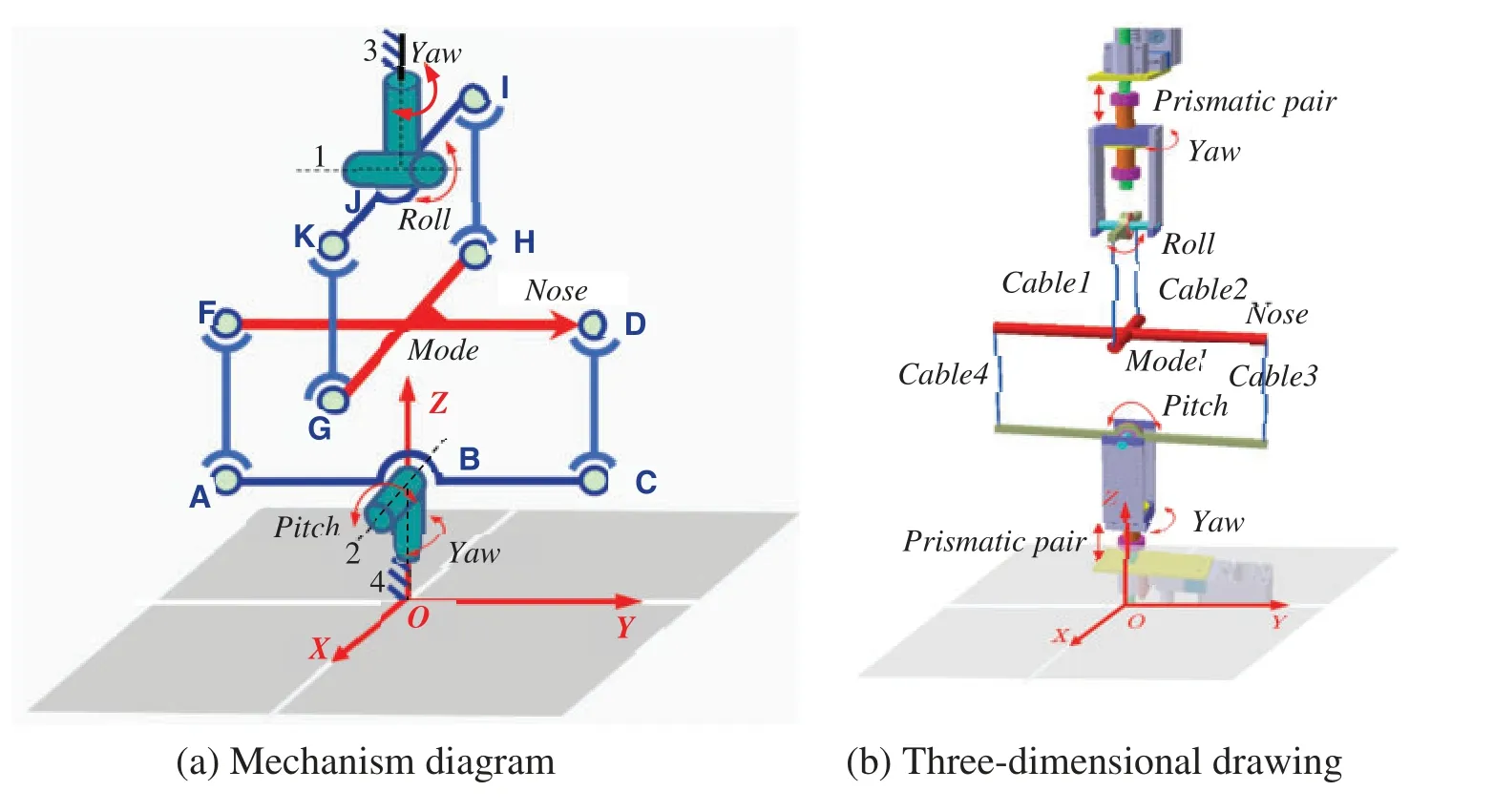
Figure 1:Underconstrained cable-driven VFT model support mechanism in wind tunnel
2.2 Degree of Freedom Analysis
With regard to Fig.1a,if a rigid rod is used to connect the cross model,the model cannot rotate around the OX and OY axis directions nor can it move along the OX,OY,and OZ directions.It can only rotate around the OZ axis, and the three degrees of freedom can rotate around the center of rotation on the corresponding parallelogram mechanism plane where the center of mass of the cross model is located.
To verify the number of degrees of freedom of the above mechanism,the modified G-K degrees of freedom formula[30]was used,as follows:
wheren,g,fi,μ, andζdenote the number containing the frame, motion pair, number of degrees of freedom of thei-th motion pair,number of overconstraints,and number of local degrees of freedom,respectively.
There were eight local degrees of freedom.The AF,CD,GK,and HI rods all have one local degree of freedom:the local degrees of freedom generated by the combination of the yaw rotation pair and the corresponding branch,and the two local degrees of freedom generated by the rotation of the cross model around its own rod,that is,the rotation of another parallelogram mechanism.Therefore,if a rigid rod is used, the total number of degrees of freedom of this VFT model support mechanism is three;specifically,the cross model has the degrees of freedom of pitch,roll,and yaw,indicating that the mechanism satisfies the support requirements of the VFT model.
Because of the low interference of the cable with the airflow and the function of the spherical pairs performed by the cable hinge point, as in Fig.1b, four cables with fixed initial lengths were used to replace the rigid rod connection model with moving pairs in the top and bottom chains, which can be controlled to tension the cables in real time.The effect of cable elasticity on dynamic modeling is considered in Section 4.
3 Structural Optimization Design and Stability Analysis
3.1 Structural Optimization Design
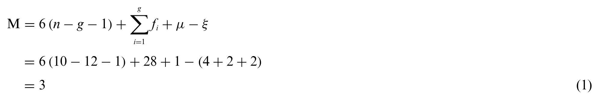
In this study,a standard dynamic test model[32],shown in Fig.2,was used for installation and commissioning.Considering the size of the wind tunnel and blocking ratio,the model was designed and processed with the scale ratio of 0.591 based on the domestic dynamic standard model,and the total mass was 2.476 kg.
Figure 2:Internal connecting mechanism of the model
Because of the complex aerodynamic shape of the aircraft model,if the cable is directly attached to the fuselage shell, it is difficult to form a complete parallelogram mechanism by combining the support rod,cable,and model,as shown in Fig.1b.Consequently,during the rotation of the model,the center of mass of the model before and after rotation do not coincide with the rotation center of the mechanism,resulting in instability.
Thus, a connection mechanism was designed inside the aircraft model, as shown in Fig.2;specifically, bearing sleeve rockers of different lengths were installed at each end of the vertical and horizontal axes for the cable connection.
The support rod for rotation around the bearing center was optimized as shown in Fig.3; the support rod can be moved along the yaw turntable direction by a distance equal to the vertical distance from the center of mass of the model to the original rotation center(as shown with the crimson bearing sleeve in Fig.3).This support platform can release different degrees of freedom of rotation in the model,and the amplitude of rotation can be adjusted.Fig.4 displays the principle of the prototype.
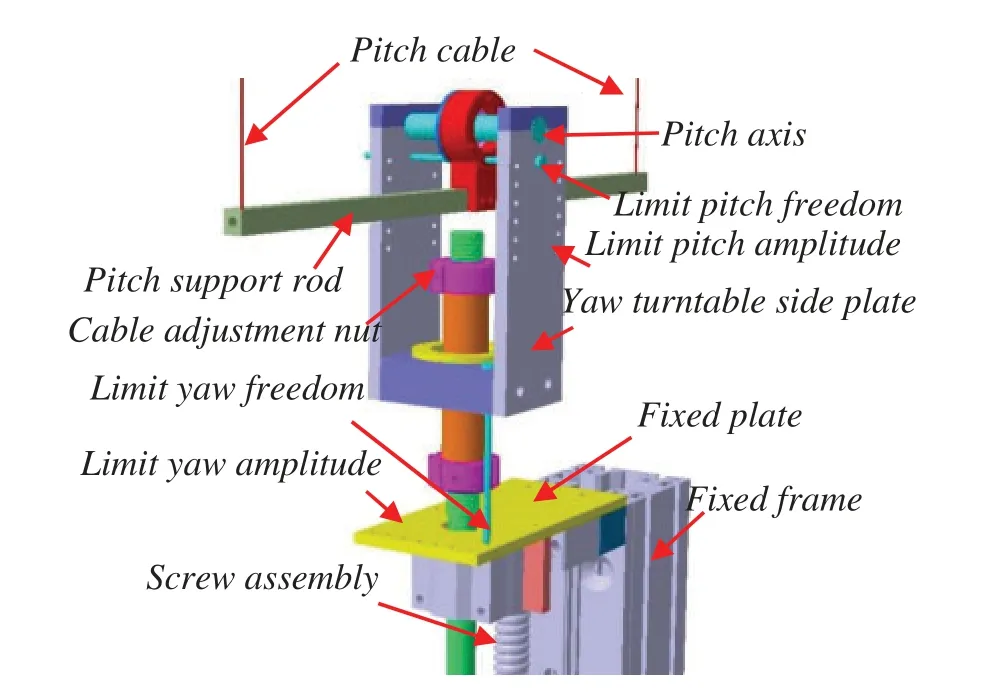
Figure 3:Optimized support platform
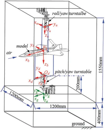
Figure 4:Principal prototype of CDPR-VFT
3.2 Stability Analysis
To verify the stability of the above CDPR-VFT,motion simulation analysis was performed using Adams software.The dynamic model in Fig.4 was assumed to be subject to control surface deflection,which is equivalent to a pitching moment of 100 N.m acting at the center of mass of the model,and the initial pretensions of the two pull-up and two pull-down cables were 32.13 and 20 N,respectively.One of the parallelogram mechanisms (with pitch as an example) was used for the analysis.For the convenience of analysis, the symmetry plane of the standard model was simplified to a straight line and stepped rectangle,and computer-aided design was used to analyze whether the center of mass and the center of rotation coincided before and after the rotation of the standard model.
When the longitudinal vertical symmetry plane of the model is simplified to a straight line,that is,the cable is connected to the longitudinal axis,the support rod,two cables,and model jointly form a parallelogram mechanism,as shown in Fig.5a.When the model is turned around the bearing center at an angleθunder the pitch moment(the elevator is given a control surface deflection angle),the center of mass of the model is coincident with the center of rotation of the support mechanism before and after the rotation of the parallelogram mechanism,and no oscillation occurs.Owing to the frictionless dissipation,the pitch angle increased linearly,as shown in Fig.5b.
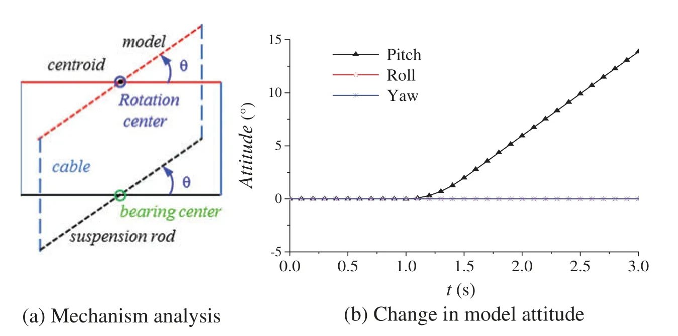
Figure 5:Model simplified as a straight line
When the symmetry plane of the model is simplified to a stepped rectangle, that is, the cable is attached to the bearing sleeve rocker,the support rod(which can be a straight rod or a stepped rod),two cables,the model,and two bearing sleeve rockers cannot form a complete parallelogram mechanism,as shown in Fig.6a.If the model rotates around the bearing center(green circle in Fig.6a)at an angleθunder the action of the pitching moment,the center of mass of the model(solid black and red dots in Fig.6a) is not coincident with the rotation center of the support mechanism before and after the rotation of the parallelogram mechanism(blue circle in Fig.6a),and a counter moment restores the model to a balanced state.The pitch angle moves back and forth,as shown in Fig.6b.
The structure was optimized, as depicted in Fig.3; that is, the support rod rotating around the bearing center was moved in the direction of the yaw turntable,the moving distance was equal to the vertical distance from the model center of mass (solid black dots in Fig.7a) to the original rotation center(blue circle center in Fig.7a),and the cable length was increased accordingly.Specifically,the bearing seat on the pitching axis of the yaw turntable of the CDPR-VFT mechanism was lengthened such that the pitching support rod moved down, as shown by the dark red bearing seat in Fig.3.Thus, the rotation center (red circle center in Fig.7a) of the support mechanism coincided with the mass center(solid black spot in Fig.7a)of the model,and the reaction moment was eliminated.The mechanism was in a stable state,and the model attitude angle changes are shown in Fig.7b.No backand-forth oscillation was observed.
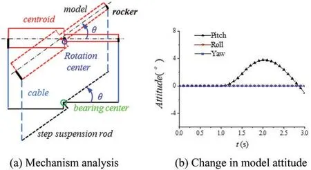
Figure 6:Model simplified as a step rectangle(before)
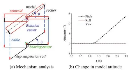
Figure 7:Model simplified as a step rectangle(after)
4 Kinematic and Dynamic Modeling
To verify the feasibility of the above model support mechanism and predict the motion of the model during VFT,kinematic and dynamic modeling were performed for this mechanism.
4.1 Kinematic Modeling
First, the kinematic relationship between the length of the tow cable and position of the model was determined.
As shown in Fig.8,three coordinate systems were established:the ground static coordinate systemOgxgygzg, airframe coordinate systemPbxbybzb(the airframe axis is along the direction ofPbxb, andPbzbpoints vertically downward to the center of the earth),and rod coordinate systemOuxuyuzu(the subscriptsuanddrepresent the upper and lower support rod,respectively).
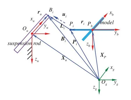
Figure 8:Kinematic modeling of CDPR-VFT
In the ground coordinate systemOgxgygzg,the cable length vector of thei-th cable is given by

whereBiis the connection point between the cable and the upper support rod.Piis the driving point of the cable in this model,XP=→OgPis the position vector of pointP(center of mass of the model)in the ground coordinate systemOgxgygzg,ri=is the position vector ofPiin the airframe coordinate systemPbxbybzb,Xu=s the position vector ofOuin the ground coordinate systemOgxgygzg,ru=is the position vector ofBiin the rod coordinate systemOuxuyuzu,RPandRuare the transformation matrices from the airframe to the ground coordinate system and from the rod to the ground coordinate system,respectively.
By further deriving Eq.(2),the relationship between the cable length change rateand the model positionXPcan be obtained as follows:

whereωbandωudenote the three-axis angular rate of the model and of the upper support rod,respectively.The model positionXPis related to ˙Liand also to the angular rates of the upper and lower support rods in the proposed mechanism.This indicates that the mechanism is an underconstrained,reconfigurable(driven point Bi time-varying),passively driven system.
4.2 Dynamic Modeling
The system dynamics analysis of multiple flexible bodies considering multiple rigid bodies and elastic deformations simultaneously is generally solved by establishing a rigid-flexible coupled dynamic model of the mechanical system (Eulerian–Lagrange differential equations); specifically,based on the first type of Lagrange equation,the Lagrange multiplier method is used to consider the system constraints and solve them simultaneously.To simplify the analysis,according to the Newton–Euler equation, and based on the unconstrained motion equation of the model with six degrees of freedom,the restraining force and restraining moment applied by four cables on the model were added.The frictional dynamic forces of key components in a multibody system should be considered when building dynamic models.For example, Ahmadizadeh et al.[33–35] used different friction models for multibody systems.Considering the elastic damping of the cables and the frictional moment of the rotating bearing of the support rod,the motion equation of the support rod rotating around the center of mass of the rod and the dynamics equations of the model under the constraint of the cable support can be established.
4.2.1 Unconstrained Motion Equation with Six Degrees of Freedom of the Model
The aircraft model is a six-degree-of-freedom motion body and its general nonlinear mathematical model can be described by the following differential equation:

where the control inputsu=denote the model elevator,aileron,rudder deflection,and throttle, respectively; the variables in the state quantitiesx= [U,V,W;P,Q,R;φ,θ,ψ;PN,PE,H]Tdenote forward, lateral, and ground velocities; roll angle, pitch angle, and yaw angle rates on the airframe coordinate system;roll,pitch,and yaw angles;and northward position,eastward position,and altitude,respectively;trepresents time;andyis the sensor measurement output.
According to the momentum theorem, momentum moment theorem, and Gothic theorem, we obtained
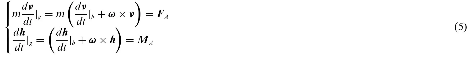
wheremdenotes the mass of the model;denote the acceleration of the model center of mass in the ground coordinate system and the airframe coordinate system, respectively;is the rate of change of momentum momenthin the ground coordinate system;is the angular acceleration in the airframe coordinate system;h=Iω,whereIis the inertia of the model,and the three components of the velocityvalong the body axis are[U,V,W]T;ωis the angular velocity of rotation in the airframe coordinate system with respect to the ground coordinate system,and its three components in the airframe body axis are[P,Q,R]T;FAis the aerodynamic force,andMAis the aerodynamic moment.
Through further calculations,the unconstrained six-degree-of-freedom dynamic equations for the model were determined as[36]
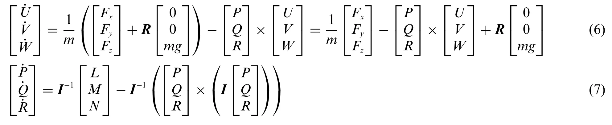
In Eqs.(6)–(7),Fx,Fy, andFzdenote the three components of the aerodynamic combined forceFAacting on the model in the airframe coordinate system,respectively;L,M,andNdenote the roll,pitch,and yaw moments acting on the model,respectively,andRis the transformation matrix from the ground static coordinate system to the airframe coordinate system.
Based on the Euler relation,the unconstrained kinematic equations of the aircraft were established as follows:
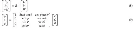
Eqs.(6)–(9)constitute the 12 underconstrained differential equations with six degrees of freedom of motion of the model.
4.2.2 Kinematics/Dynamics Equation of a Support Rod Rotating about Its Centroid
The coordinate system shown in Fig.9 was established.For the convenience of modeling, the initial position of the center of gravity of the airframePbwas set at[0,0,-1.175](unit:m)under the ground coordinate systemOgxgygzg.TheOuxuaxis of the upper rod coordinate systemOuxuyuzuand thePbxbaxis of the airframe coordinate systemPbxbybzbwere perpendicular to each other,whereas theOdxdaxes of the lower rod coordinate systemOdxdydzdand thePbxbaxis of the airframe coordinate systemPbxbybzbwere in the same direction.
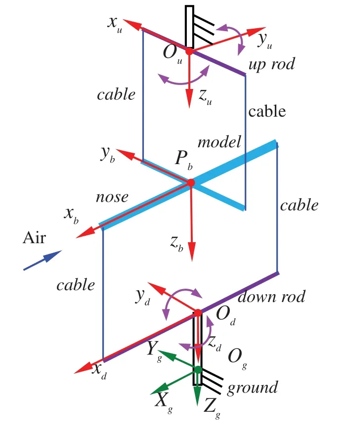
Figure 9:Dynamic modeling coordinate system definition of CDPR-VFT
The rigid body was rotated around thex,y,andzaxes with rotation angle(assumed asη),and the corresponding transformation matrices can be written as

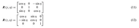
The Euler coordinate system transformation was performed in this study as follows:the ground coordinate system was rotated and transformed in the order ofR=R(x,φ)R(y,θ)R(z,ψ)to obtain the body coordinate system,andR-1=RT.The rotation matrix from the body axis system coordinate to the ground axis system coordinate isRT.Similarly,the ground coordinate system was rotated and transformed in the order ofR=R(x,0)R(y,θ)R(z,ψ)to obtain the rod coordinate system.The rotation matrix from the body coordinate system to the speed coordinate system isS,αandβare the angles of attack and sideslip angle,respectively,andS-1=ST,whereSis given by

The cable produces elastic deformation under tension, and the cross model may exhibit small oscillations in movement,which influences the stability of the mechanism.Therefore,elastic damping of the cable was considered in the dynamic modeling,the cable was simplified as a spring model,and its tension equation[29]is given by

whereTdenotes the cable tension vector,kadenotes the cable stiffness,cdenotes the damping coefficient of the cable,Ldenotes the real-time cable length vector, andLadenotes the undeformed cable length vector.In this study,a Kevlar cable with the diameter of 1.2 mm was used as the driving cable, with the elastic modulusE= 43.9 GPa, andka=EA/La= 1.323 × 10⁵N.m, whereAis the cross-sectional area of the cable.
The frictional moment model for the upper support rod rotating bearing[10,16]is expressed as

whereTcandTsare the Coulomb and static frictional moments [N.m].The parameterαf[s/m]was introduced such that the model conforms to the Stribeck effect;α2is the viscosity coefficient[N.m s/rad].
The resultant forceTband resultant momentMbgenerated by the four cables in the model are expressed as follows:

whereTigis the tension of thei-th cable in the ground coordinate system,Ris the transformation matrix from the ground coordinate system to the airframe coordinate system,ribis the position vector of pointPion the aircraft model corresponding to thei-th cable in the body axis system,i=1,2,3,4 denote the upper-left,upper-right,lower-front,and lower-rear cables in Fig.9,respectively.
The acting moment of a single cable on the support rod in the rod system coordinates is given by

whereriu(d)is the position vector of pointBion the upper rod(lower rod)corresponding to thei-th cable in the rod system,andTiu(d)is the cable tension of thei-th cable in the upper rod(lower rod)coordinate system.
The resultant momentsMuandMdof the upper and lower support rods,respectively,are

The kinematic and dynamic differential equations for the upper(or lower)support rod rotating around its center of mass are as follows:
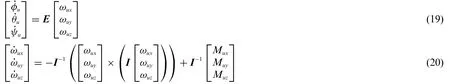
whereφu,θu, andψudenote the three-axis attitude angles of the upper support rod;ωxy,ωuy, andωuzdenote the components of the angular rate of the upper support rod along the three coordinate axes;Mux,Muy,andMuzdenote the components of the resultant moment of the upper support rod along the three coordinate axes;Eis the Eulerian transformation matrix;andIis the rotational inertia matrix of the upper support rod.
Eqs.(19) and (20) constitute the kinematic and dynamic differential equations of the upper support rod rotating around its own centroid.These equations together with those for the lower support rod form 12 differential equations for the motions of the upper and lower support rods.
4.2.3 Constrained Cable-Driven Equations of Motion of the Model
In this study,a simulation of the cable-driven VFT model was conducted,and the model shown in Fig.2 was adopted.Its aerodynamic model(aerodynamic forceFAand aerodynamic momentMA)was obtained by calculating the interpolation,and collecting the wind tunnel test aerodynamic database[37]and related information.
The resultant forceFand the resultant momentMapplied to the model are given by

The constrained cable-driven kinematic and dynamic equations of the model were obtained by substituting the resultant force and resultant moment applied to the model into the unconstrained six-degree-of-freedom equations of motion of the model.
From the above equations, the nonlinear functional relationship between the state quantitiesx= [U,V,W;P,Q,R;φ,θ,ψ;PN,PE,H]Tof the constrained cable-driven model and the control quantitiesu=[δe,δa,δr,δeng]Tcan be established,as well as the relationship between the state quantitiesandof the upper and lower rods,and the cable tension and frictional moment.Equations are closed.
The position of the aircraft model is intrinsically related to the cable length and tension;that is,for the underconstrained,reconfigurable(driven pointBitime-varying),passively driven cable-driven mechanism designed in this study,the geometric equations of motion and force balance equations are coupled with each other,and their relevant parameters can be determined from the joint solution.
5 System Stiffness and Stability Criteria
For further derivation of the relationship between the change rate of cable length obtained using Eq.(3)and the pose of the aircraft model,we obtained

Eq.(22) represents the relationship between the speed vector of the cable and motion speed vector of the moving platform,whereJAis the Jacobian matrix of the mechanism.The helical balance equation of the force on the aircraft model and support rod can be expressed as

whereWRis the force helix acting on the model and the support rod,andTis the cable tension matrix.WhenWRexhibits a small change inδWR, the aircraft model corresponds to a small change inδX.Based on the differential transformation principle,the stiffness of the cable-driven parallel mechanism satisfies

WhenWRis applied to the aircraft model,the cable length vectorLexhibits a corresponding small changeδL.According to the virtual work principle,δLandδXsatisfy

Through the derivation of Eqs.(22)–(25),the total stiffness matrix of the system could be obtained as follows:

whereK1is related to the cable tension,K2is related to the cable-driven arrangement point and pose of the model,andK3is related to the rotation angular velocity of the model,upper and lower support rods,and cable tension.
In this study,the CDPR-VFT mechanism is an underconstrained parallel support mechanism,and the necessary and sufficient condition for the stability of the system is that the Hessian matrix based on the total stiffness of the system is positive definite[38].The Hessian matrix equation is written as follows:

whereN= null(J)is the zero-space matrix andHis the stiffness matrix of the under-constrained,reconfigurable cable-driven parallel support mechanism constructed using Eq.(26).This support mechanism is stable if and only ifHris positive;specifically,when all eigenvalues ofHrare positive,the mechanism is stable.
To verify the stability of the aforementioned underconstrained mechanism, when the support mechanism is locked, the aircraft model attitude angle, cable preload, and other parameters are substituted into Eq.(27), theHrmatrix can be obtained, and the stability of the mechanism can be judged by the eigenvalues ofHr.
Example 1:pitch angle of aircraft modelθ=10°.When the initial preloads of two pull-up and two pull-down cables are 32.14 and 20 N,respectively,all eigenvalues of theHrmatrix form a diagonal matrixdiag(Dr),whereDris

Example 2:pitch angle of aircraft modelθ=20°.When the initial preloads of two pull-up and two pull-down cables are 32.14 and 20 N,respectively,all eigenvalues of theHrmatrix form a diagonal matrixdiag(Dr),whereDris

From Eqs.(28)and(29),it can be seen that all eigenvaluesDrofHrare greater than zero;thus,the support mechanism is locked in this configuration,and the aircraft model is stable under the condition of maintaining static balance.
6 Simulation Analysis
To verify the correctness of the above flight dynamics model and the feasibility of the support mechanism, the Simulink module in MATLAB was used to perform a simulation analysis.To analyze the influence of friction torque on the support mechanism and that of the constraints of the support mechanism on the motion of the model,the stability of the support mechanism was first investigated,and then three different working conditions were used for comparison:the model without friction torque (CDPR-VFT), the motion with friction torque (CDPR-VFT+F friction) under the support constraint, and the unconstrained motion of the model (three degrees of freedom (3DOF)unconstrained).The main parameters of the aircraft model,support rods,and cables are presented in Table 1.
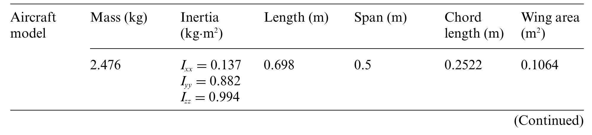
Table 1: Main parameters of aircraft model,support rod,and cable
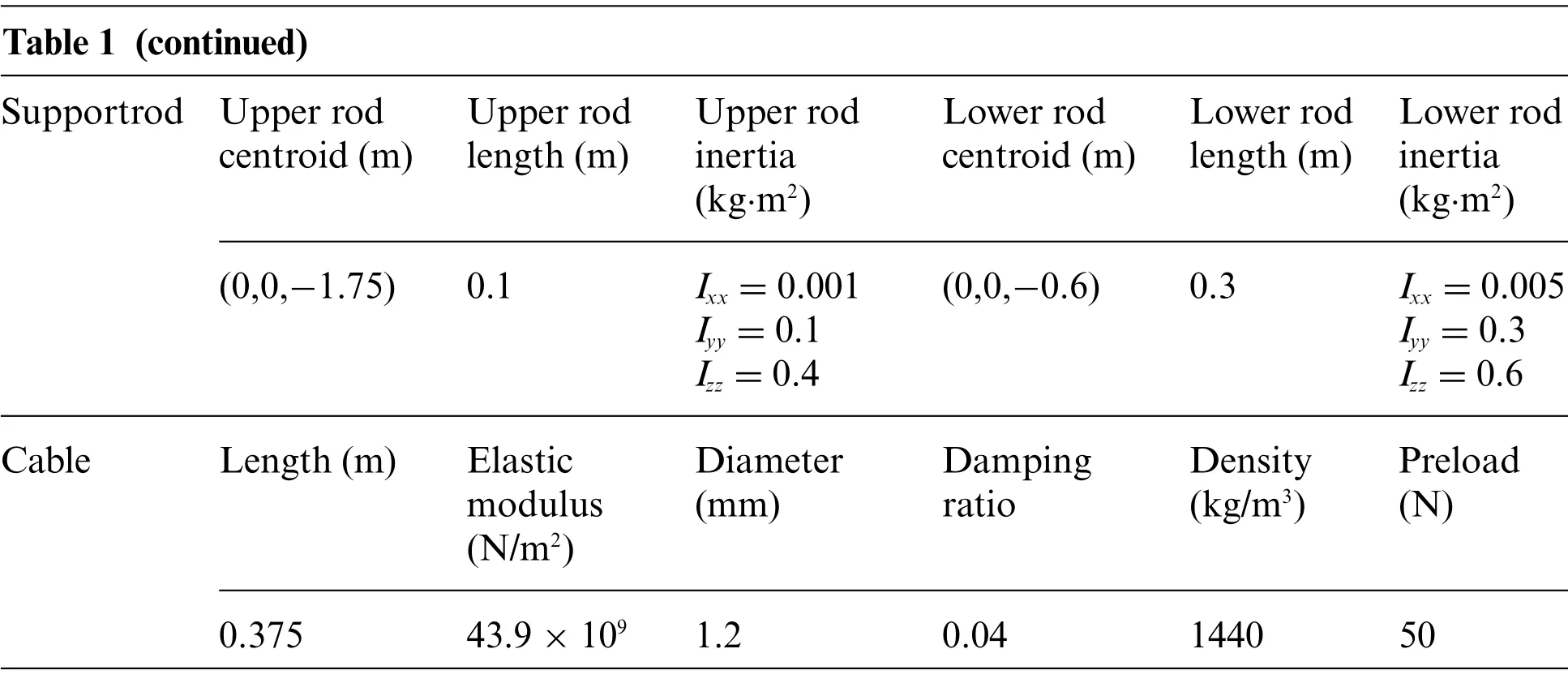
Table 1 (continued)Supportrod Upper rod centroid(m)Upper rod length(m)Upper rod inertia(kg·m2)Lower rod centroid(m)Lower rod length(m)Lower rod inertia(kg·m2)(0,0,-1.75) 0.1 Ixx=0.001 Iyy=0.1 Izz=0.4(0,0,-0.6) 0.3 Ixx=0.005 Iyy=0.3 Izz=0.6 Cable Length(m) Elastic modulus(N/m2)Diameter(mm)Damping ratio Density(kg/m3)Preload(N)0.375 43.9×10⁹ 1.2 0.04 1440 50
6.1 Stability Analysis of Mathematical Models
First, the simulation was performed after initial trimming (trimming angle of 2.1°).Without controlling surface deflection and wind speed,the head-up pitch angle of the model was considered as 1°,and the initial preload force of the cable was 40 N to examine the variation of the model and the pitch support rod.
As shown in Fig.10,the initial negative moment applied to the model decreased the pitch angle,the model headed downward, and the lower crossbar was subjected to a positive pitching moment,which increased the pitch angle.They oscillated back and forth in the equilibrium position,and their amplitude decayed continuously.The pitch angle of the model finally stabilized at 0.96°, indicating that the curve tendency is reasonable, and the mechanism is stable.The amplitude of the crossbar oscillation is large and is related to the cable preload force and rotational inertia.
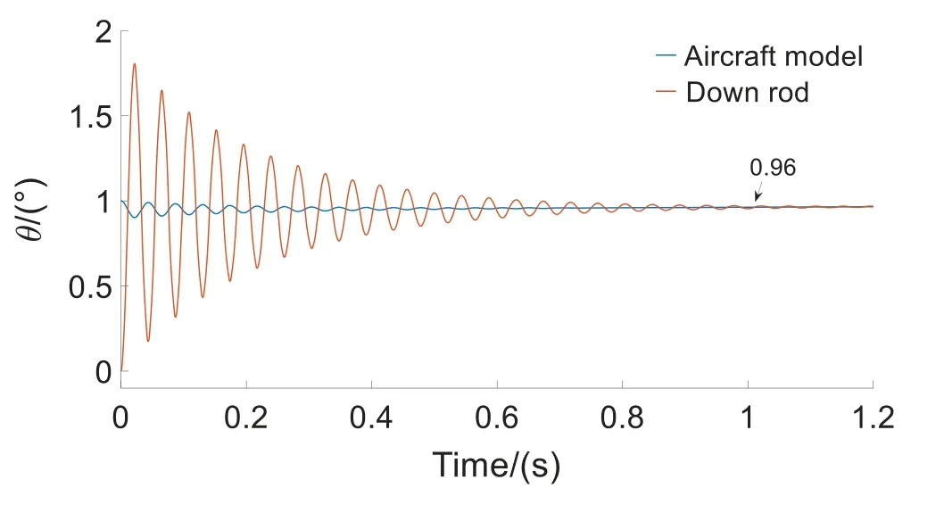
Figure 10:CDPR-VFT mechanism oscillation simulation
The above results demonstrate that owing to the elastic damping of the cable,slight oscillations occur during the movement of the mechanism,but they quickly stabilize.If the cable is tightened by a moving pair in the screw assembly of the mechanism,the preload force of the cable can be increased to reduce this slight oscillation.
6.2 Analysis of Typical Longitudinal Manipulation Response
Owing to space limitations, only the typical longitudinal manipulation response of the CDPR-VFT was investigated in this study.
The typical longitudinal manipulation input signal was selected,that is,when the wind speed was stabilized at 20 m/s,the elevator step of 1°was input and the step point was at 10 s.The manipulation response of the elevator is depicted in Figs.11–15.
6.2.1 Analysis of the Effect of Friction Moment
To analyze the influence of the frictional moment of the crossbar bearing on the mechanism of the support system, two cases of the support mechanism without and with frictional moment were selected for comparison.
The simulation results in Figs.11–13 illustrate that the elevation of 1° results in a negative pure pitch moment and the model is in steady state at 3.12 s,following several back-and-forth oscillations.No roll or yaw motions for the model and cable-driven support mechanism are observed.The attack angle was equal to the pitch angle.The frictional moment had a damping effect on the pitch motion,and the damping decreased the attack angle and pitch angle by approximately 0.005°.Moreover,the damping decreased the peak of pitch rate,which was approximately 0.02°/s,indicating that the friction moment has little effect on the support mechanism.
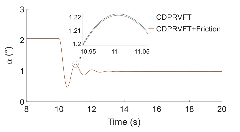
Figure 11:Change in attack angle
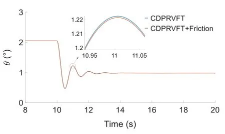
Figure 12:Change in pitch angle
6.2.2 Comparative Analysis with Unconstrained Rotation with Three Degrees of Freedom
To analyze the response characteristics of the entire support mechanism to the model,a simulation of unconstrained rotation with three degrees of freedom was introduced for comparison data to verify the correctness of the mechanism.
Fig.14 illustrates that the cable-driven virtual flight support mechanism of the model designed in this study is consistent with the tendency of the simulation results of the unconstrained rotation with three degrees of freedom, which lags by approximately 0.04 s because of the effects of friction and cable elasticity.

Figure 14:Change in pitch angle
6.2.3 Analysis of the Effect of Center of Mass Displacement
The variation in the center of mass displacement of the model under the longitudinal manipulation input is shown in Fig.15.
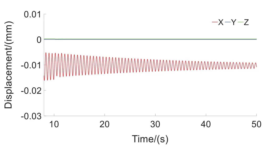
Figure 15:Displacement change of center of mass of model
Fig.15 illustrates that the displacement of the center of mass of the model along the three axes is very small, and the maximum displacement along the X-direction of the nose is 0.01 mm.The amplitude of oscillation becomes gradually smaller,and finally reaches a stable state.The cable-driven VFT model support mechanism basically restrains the three translational degrees of freedom and releases the three rotational degrees of freedom,which meets the support requirements of the WTBVFT model.
6.2.4 Analysis of the Effect of Cable Preload
The change in the preload of the different cables under the above longitudinal manipulation input is shown in Fig.16.
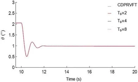
Figure 16:Effects of different cable preloads on longitudinal control response
Because the tension change caused by the elastic deformation of the cable in this study was relatively small compared with the aerodynamic force and control torque,the effect of increasing the cable preload on the longitudinal control response was very small.Owing to the elasticity of the cable,the mechanism inevitably had a small translation,but this allowed for the translation requirements of the supporting mechanism of the VFT model because WTB-VFT focuses more on releasing the three rotational degrees of freedom of the model.
7 Experimental Verification
According to the dynamic similarity criterion[14],the model depicted in Fig.17 was processed in this study,and an open-loop control experiment of pitching a single degree of freedom was conducted.The cross-section of the wind tunnel outlet was 600 mm×600 mm and the wind speed was 10 m/s.The motion response process of the model was investigated to verify the feasibility of the mechanism shown in Fig.18.
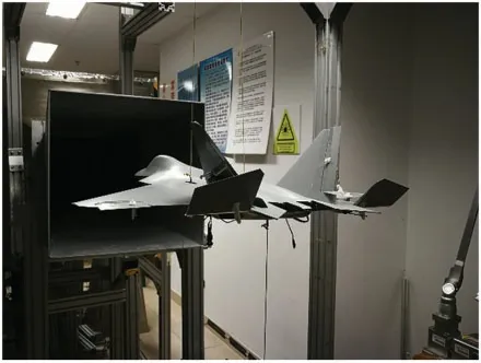
Figure 17:Principal prototype in wind tunnel test
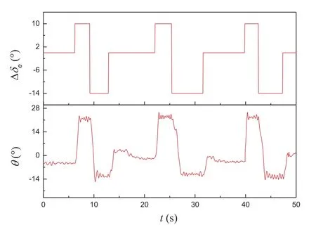
Figure 18:Elevator open loop control test
After the model was trimmed, an elevator dual square-wave maneuver was performed to excite the short-period modal motion of the model.The initial pitch angle of model trim was -4.5°, and the elevator moved from 0°to the negative direction of the control surface(i.e.,the positive direction ofδein the figure deflected to 10°).The model obtained the pitching moment of the head,and the pitching angle rose to approximately 22° with small amplitude oscillation.The elevator deflected to 14° in the positive direction of the control surface, and the model obtained the pitching moment of the lower head.The pitching angle decreased to approximately-12°and became stable after a small oscillation.Finally,the elevator returned to zero,the model obtained the pitching moment of the lift,and the pitching angle returned to near 0°.The dual square-wave maneuver was repeated three times,and the motion response state of the model remained basically the same.
Fig.18 shows that the lift characteristics of the model are evident.The change in the model pitch angle obtained by deflecting the elevator in the negative direction of the control surface was considerably larger than that obtained by deflecting the elevator in the positive direction of the control surface.After each square-wave step maneuver, the pitch angle of the model oscillated slightly and tended to stabilize.This is due to the interaction between the inertia and air damping of the model,and the overall tendency is similar to that of typical longitudinal manipulation simulation results(see Fig.12),verifying the feasibility of the CDPR-VFT mechanism.
8 Conclusions
In this study,CDPR-VFT was designed.Through mechanism design,dynamic modeling,simulation analysis,and experimental verification,the following conclusions were obtained:
1) The CDPR-VFT mechanism was designed according to the mechanism theory.Through the degree of freedom verification,it is proved that the mechanism can realize the free coupling and decoupling of the model with three rotational degrees of freedom and meet the requirements of the WTB-VFT model support;
2) Structural optimization and stability analysis of the CDPR-VFT were performed,proving that the optimized mechanical structure has good stability;
3) A mathematical model of the kinematics and dynamics of the cable-driven underconstrained,reconfigurable,passively driven mechanism was developed for the CDPR-VFT,which considers the cable elasticity and friction moment,on which the stiffness and stability criteria of the system are derived, and an example is provided herein.Finally, simulation and experimental methods were used to analyze the response of the model to typical longitudinal maneuvers in VFT.The results show that the CDPR-VFT model support mechanism has little effect on the motion of the vehicle model,which verifies the feasibility and validity of the mathematical model.
The CDPR-VFT developed in this study can provide conditions for conducting integrated research on aerodynamics/motion/control of aircraft models,exploring the mechanism of aerodynamics/motion coupling of aircraft models,identifying aerodynamic parameters of models,and providing a reference for designing cable-driven WTB-VFT models.
Funding Statement:The authors received no specific funding for this study.
Conflicts of Interest:The authors declare that they have no conflicts of interest to report regarding the present study.
 Computer Modeling In Engineering&Sciences2023年4期
- Computer Modeling In Engineering&Sciences的其它文章
- A Study of BERT-Based Classification Performance of Text-Based Health Counseling Data
- Overview of Earth-Moon Transfer Trajectory Modeling and Design
- CEMA-LSTM:Enhancing Contextual Feature Correlation for Radar Extrapolation Using Fine-Grained Echo Datasets
- The Class of Atomic Exponential Basis Functions EFupn(x,ω)-Development and Application
- Corpus of Carbonate Platforms with Lexical Annotations for Named Entity Recognition
- Unique Solution of Integral Equations via Intuitionistic Extended Fuzzy b-Metric-Like Spaces