
Influence of Vertical Load on Lateral-Loaded Monopiles by Numerical Simulation
2023-03-12 09:00QiangLiPanChenLihongGaoDanMengandJinjieZou
Qiang Li,Pan Chen,Lihong Gao,Dan Meng and Jinjie Zou
1Huadong Engineering(Shenzhen)Corporation Limited,Shenzhen,518100,China
2Faculty of Civil Engineering and Geosciences,DelftUniversity of Technology,Delft,2628 CN,The Netherlands
ABSTRACT Monopiles are the most common foundation form of offshore wind turbines,which bear the vertical load,lateral load and bending moment.It remains uncertain whether the applied vertical load increases the lateral deflection of the pile.This paper investigated the influence of vertical load on the behaviour of monopiles installed in the sand under combined load using three-dimensional numerical methods.The commercial software PLAXIS was used for simulations in this paper.Monopiles were modelled as a structure incorporating linear elastic material behaviour and soil was modelled using the Hardening-Soil(HS)constitutive model.The monopiles under vertical load,lateral load and combined vertical and lateral loads were respectively studied taking into account the sequence of load application and pile slenderness ratio(L/D;L and D are the length and diameter of the pile).Results suggest that the sequence of load application plays a major role in how vertical load affects the deflection behaviour of the pile.Specifically,when L/D ratios obtained by lengthening the pile while keeping its diameter constant are 3,5 and 8,the relationships between lateral load and the deflection behaviour of the pile under the effect of vertical load demonstrate a similar trend.Furthermore,the cause of increased lateral capacity of the pile under the action of applied vertical load in the common practical application case and in the VPL case was analyzed by studying the variation law of soil stress along the pile embedment.Results confirm that the confining effect of vertical load increases means effective stress of the soil around the pile,thus increasing soil stiffness and pile capacity.
KEYWORDS Pile;lateral capacity;combined load;sequence of load application;L/D ratio
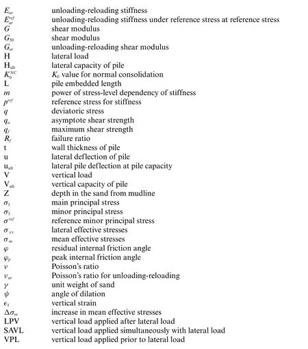
List of Notation
1 Introduction
As a result of low-carbon green growth policies, many countries have mandated an increase in renewable energy production.The international market for renewable energy is therefore growing steadily each year.Among various clean and renewable energy sources, wind energy has proved particularly attractive [1], equivalent to approximately 199 GW.The market is rapidly expanding in many countries,including the United States,Northern Europe,Japan,China and Korea[2].Based on the historical data from 1980 to 2010 and combined with data forecast for the period of 2010 to 2050,wind energy is estimated to meet more than 20%of the world’s electricity demand by mid-century[3].
Of all the foundations,monopiles are the most preferred[4,5],accounting for more than 87%of the total installations by 2018[6].As a supporting substructure of offshore wind turbines,monopiles are required to resist both the vertical load from self-weight and the lateral loads from wind, wave and currents.To date,in view of relatively small vertical load,monopile design is dominated by lateral loads.However,due to increased turbine size(larger vertical load from self-weight)and hub heights(higher lateral loads from wind)for larger electric capacity,monopile response under combined load has attracted industrial interest.
The lateral resistance of monopiles under combined load has been studied numerically by a number of researchers[7].Klein et al.[8]performed Finite Element Analyses(FEA)on a pile subjected to vertical and lateral loads and found that vertical load would both increase and reduce its lateral capacity depending on the geotechnical properties of sand.Madhav et al.[9] studied the response of long piles in clay under combined load using the Finite Difference Method (FDM).The results indicated that extra vertical load would induce larger lateral deflections and moments along the pile by more than 100%.Trochanis et al.[10] investigated the influence of soil non-linearity on pile response under monotonic and cyclic load through three-dimensional finite element analyses using an elastoplastic model for soil.They found that lateral load-deflection curve is virtually unaffected by vertical load.Similar observation was also reported by Abdel-Rahman et al.[11].However,Karthigeyan et al.[12,13]performed three-dimensional finite element analyses on the lateral response of piles installed in both homogeneous clayey and homogeneous sandy soil and found that at a given lateral load,pile lateral deflection decreased with the increase of vertical load.In addition,the influence of vertical load on the lateral pile response was observed to be more significant in dense sand than in loose sand.
Achmus et al.[14,15] performed numerical simulations to identify and quantify the effects of combined vertical and lateral loads on piles in sandy soil using ABAQUS.An elastoplastic material law with Mohr-Coulomb failure criterion and stress-dependent stiffness was implemented.The results showed that under vertical compressive loads,pile lateral capacity was increased.However,interaction behaviour was complex.Depending on load condition,opposing effects on system stiffness and lateral load capacity could be observed.Haiderali et al.[16]investigated the lateral and vertical response of monopiles installed in undrained clays of varying shear strength and stiffness using three-dimensional finite element analysis.It was found that variation in vertical loads did not have a significant effect on the ultimate lateral capacity of monopiles within the operational vertical load range.Taheri et al.[17]conducted a full three-dimensional finite element analysis on a reinforced concrete pile embedded in silty sand subjected to vertical and lateral loads using ABAQUS.Simulation results showed that the lateral deflection of both long and short piles was considerably reduced under vertical load.The various works and main conclusions describing the influence of vertical load on lateral response of piles subjected to combined load are summarised in Table 1.Researches have revealed contradictory findings, which is very likely to be caused by soil type, modelling assumptions, constitutive laws,relative load magnitude,pile slenderness,boundary conditions,and other considerations such as load application sequence.No general consensus has been drawn on whether vertical load increases or reduces subsequent lateral displacement under lateral load.The behaviour of monopiles especially installed in sandy deposits(the North Sea geologic setting)under combined load needs to be clarified.
This paper numerically studied the effect of vertical load on the lateral response of openended monopiles in the sand.The influence of load application sequence, load magnitude and pile slenderness ratio (L/D; L, pile length, and D, pile diameter) was investigated.PLAXIS 3D [18] was used for the FEA.In all cases considered,the pile was embedded in homogeneous dry sand and was assumed to be fully drained[19].More details about the simulations can be found in Section 2.
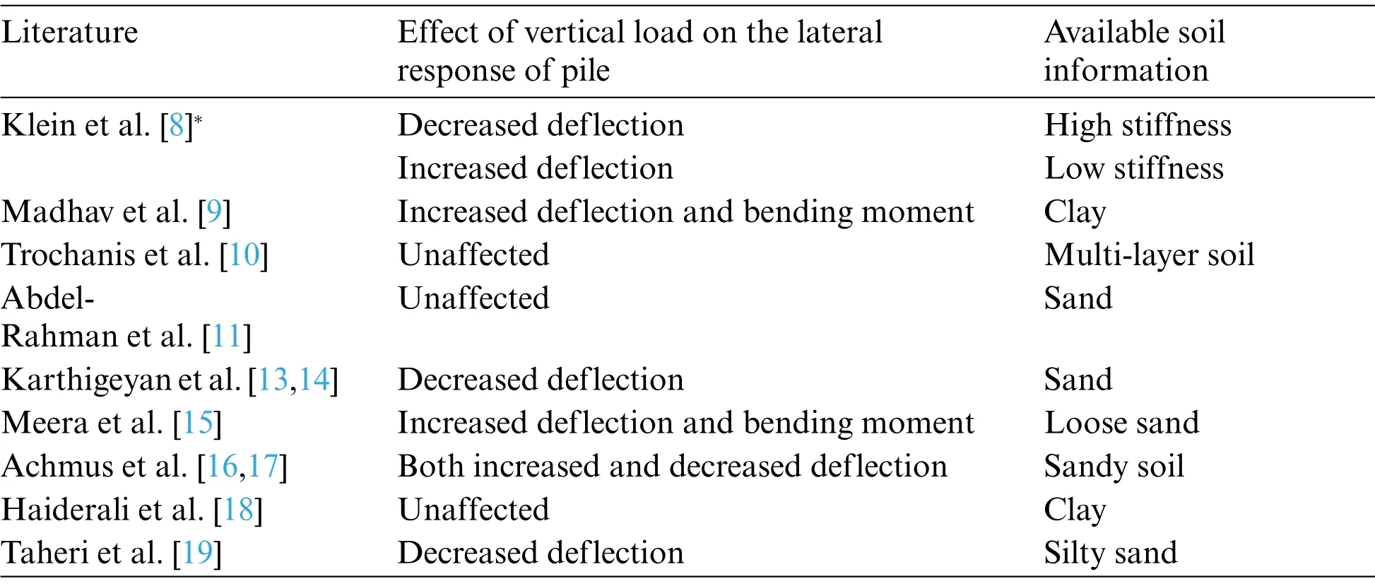
Table 1: Summary of the effect of vertical load on the lateral response of piles
2 Finite-Element Modelling
A typical three-dimensional finite element mesh of pile-soil system used in this study is shown in Fig.1.Considering the symmetry of the problem, only half of the pile-soil system was modelled to improve computation efficiency.The model mesh was 40D long and 20D wide.The model was 20D beneath the pile tip.As can be seen from Fig.1,the mesh around the pile was highly refined.All the nodes on the lateral boundaries were restrained in the normal direction, while the bottom surface was completely fixed in all three directions.Additional simulation using a model of double size and mesh density exhibited little change in the lateral load-deflection response of pile(less than 2%),which justified the accuracy of the model adopted in Fig.1.
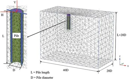
Figure 1:Typical mesh adopted in three-dimensional finite element analyses
A series of analyses were performed on a single free-headed pile in sand.The material behaviour of the piles was assumed to be linearly elastic with the parametersE=210 GPa(Young’s modulus)andν=0.2(Poisson’s ratio)for steel.The pile geometries considered are summarised in Table 2.The Hardening-Soil(HS)model was employed to describe the nonlinear behaviour of dense sand.
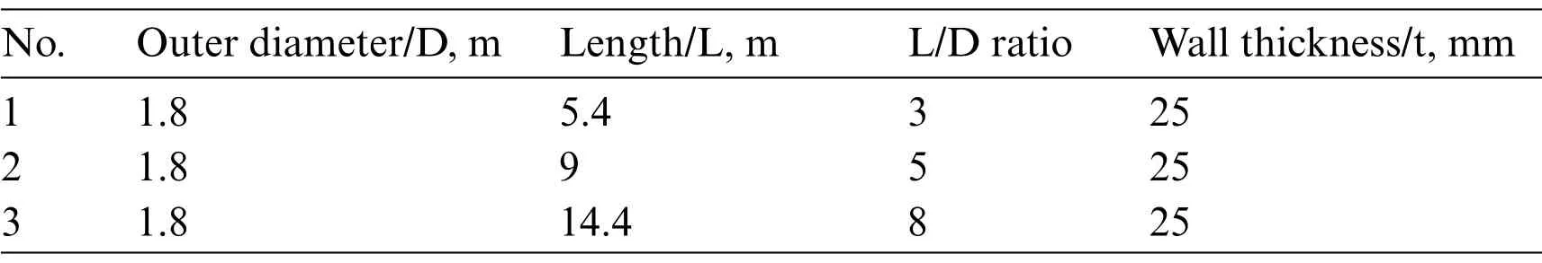
Table 2: Pile geometries
The Hardening-Soil model contained eight parameters,including three basic parameters for soil stiffness[20,21]:
stiffness modulus for primary loading under reference stress,
tangent stiffness for primary oedometer loading under reference stress and
m,power for stress level dependency of stiffness,
and five advanced parameters:
unloading/reloading stiffness under reference stress,
υur,Poisson’s ratio for unloading and reloading,
pref,reference stress for stiffness,
0value for normal consolidation and
Rf,failure ratioqf/qa.
The Harding-Soil model assumed a hyperbolic relationship between vertical strain∈1and deviatoric stressqin primary triaxial loading,compared with the bi-linear curve in Mohr-Coulomb model.In addition,the model also captured the stress level dependency behaviour of sand.In this regard,the secant stiffness modulus at half of shear strength (E50), the elastic unloading modulus (Eur) and the oedometer modulus(Eoed)in Hardening-Soil model were independently defined by a reference minor principal stress ofσ3=σrefforEoed,as shown in Eq.(1).Theandneeded to be defined.According to the Hook’s theory,shear modulus(Gur)was calculated byEur=2(1+ν)Gur.

More details about the HS model and the calibration of model parameters can be found in Schanz et al.[20]and Brinkgreve et al.[21].The parameters employed in this paper were derived on the basis of an assumed relative density of sand(80%)using the empirical formulas recommended by Brinkgreve et al.[22].
In order to apply load at the central point of the pile cross-section,the pile top was closed by a steel plate with a thickness of 50 cm,making it sufficiently rigid and preventing obvious deformation during loading.The sand inside the pile was removed to 1 m below the original mudline to eliminate the possibility of extra pile resistance.
To analyse the response of piles under combined load, several loading cases were considered.Vertical loads with magnitudes of 0.2,0.4,0.6,0.8 and 1 Vultwere applied,where Vultis vertical load capacity,defined as vertical load(V)at a vertical pile displacement of 0.1D[23]obtained by analysing a single pile only subjected to vertical load.Similarly,lateral load capacity(Hult)was defined as lateral load(H)resulting in a lateral pile deflection(u)of 0.1D(uult)at the pile head.Concerning combined load,vertical and lateral loads were applied in different sequences,which is presented in the subsequent section.The influence of vertical and lateral load magnitude was also investigated.The analysis in the lateral direction was performed under load-controlled conditions and lateral deflection developed under lateral load was studied.The influence of different slenderness ratios (L/D) of piles on pile behaviour under combined load was also explored.The pile slenderness was adjusted by changing pile length while keeping pile diameter constant.
The finite element calculations were executed in several phases.Firstly, initial stress state in the system caused by the self-weight of the soil was generated using soil elements only.Subsequently,pile elements were generated by assuming a‘wished in place’state,i.e.,the installation process of the pile was not modelled.The soil elements within 1 m from the original mudline inside the pile were removed.The various loading stages were specified in PLAXIS,more details of which are provided in the subsequent sections.
3 Analysis and Results
The analysis results of piles under combined load are given in this section.Section 3.1 investigates how the lateral response characteristics of pile vary with load application sequence,while Section 3.2 quantifies the influence of pile slenderness on pile response.Section 3.3 further reveals the underlying mechanism that governs the combined loading response of monopiles by investigating soil stress state around the pile.
3.1 Influence of Load Application Sequence on Pile Response
Influence of vertical load on pile lateral response was investigated considering different load application sequences and varying load magnitudes.Monopiles with a diameter of 1.8 m and lengths of 5.4, 9 and 14.4 m, were respectively studied, as presented in Tables 2 and 3 with full modelling properties employed.The vertical load was applied to a pile in three different sequences(see Fig.2),(i)prior to lateral load(VPL,Fig.2a),(ii)simultaneously with lateral load(SAVL,Fig.2b),and(iii)after lateral load(LPV,Fig.2c).The deflection of pile top was extracted from the central node on the head plate of the pile model.
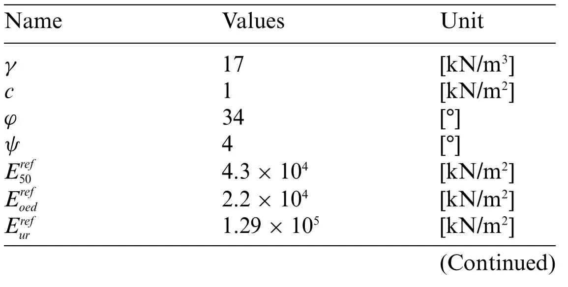
Table 3: Parameters for the soil model
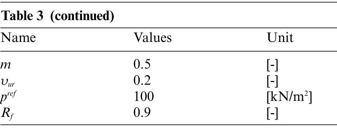
Table 3 (continued)Name Values Unit m 0.5 [-]υur 0.2 [-]pref 100 [kN/m2]Rf 0.9 [-]
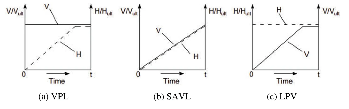
Figure 2:Schematic illustration of load sequence(a)VPL(b)SAVL(c)LPV
Firstly, the vertical load capacity (Vult) and lateral load capacity (Hult) of a single pile were separately evaluated in numerical analyses.The loads were applied incrementally in two directions to the pile up to a displacement of 0.1D(0.18 m).As shown in Fig.3a,Vultfor piles with L/D ratios of 3,5 and 8 were calculated as 2800,4750 and 8100 kN,respectively.Meanwhile,as shown in Fig.3b,Hultfor piles with L/D ratios of 3,5 and 8 were calculated to be 680,1450 and 2650 kN,respectively.
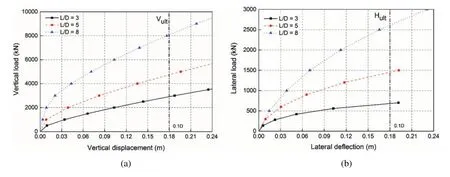
Figure 3:(a)Vertical load-displacement relationship and(b)Lateral load-deflection relationship
For the implementation in the numerical model,vertical and lateral loads were divided into five stages, namely V = {0.2 0.4 0.6 0.8 1} Vultand H = {0.2 0.4 0.6 0.8 1} Hult.In the VPL case, a given vertical load was applied, namely V = 0.2 Vult, and lateral load was iteratively increased from 0 to Hult.The vertical load was then iterated to the next increment.The above process was repeated.In the SAVL case, a given vertical load was further sub-divided into five load sub-steps (for example,for the vertical load V=0.2 Vult,incremental loads V={0.2 0.4 0.6 0.8 1}×0.2 Vultwere specified).The vertical and lateral loads were then increased simultaneously.In the LPV case,a given lateral load was applied firstly and vertical load was then increased from 0 to Vultin the increments specified.The load-deflection responses of piles with L/D ratios of 5 in three cases are presented in Fig.4.
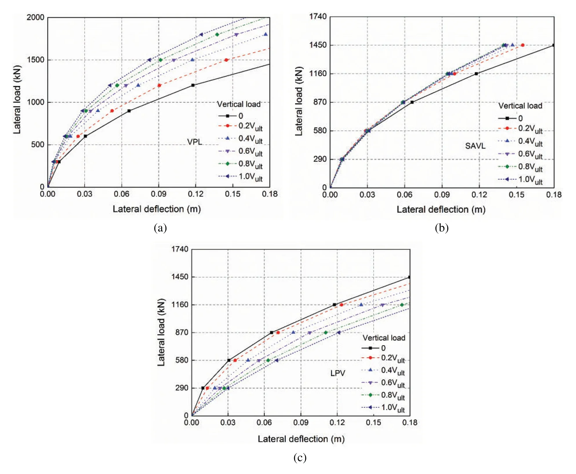
Figure 4:Lateral load-deflection behaviour for cases(L/D=5):(a)VPL,(b)SAVL,and(c)LPV
Figs.4a–4c show the lateral loadvs.lateral deflection responses of a pile with a slenderness(L/D)ratio of 5 in dense sand in the cases of VPL,SAVL and LPV.As shown in the figure,at a given lateral load magnitude,with the increase in vertical load,lateral deflection significantly decreased in the VPL case and marginally decreased in the SAVL case.Furthermore,with the increase in vertical load,lateral deflection was observed to increase in the LPV case.In the VPL case in Fig.4a, at a certain lateral load, the corresponding lateral deflections decreased nonlinearly with the increase of vertical load magnitude,i.e.,the rate of lateral deflection decreased.In the SAVL case in Fig.4b,at a certain lateral load,lateral deflection decreased with the increase of vertical load magnitude,but not proportionally.The first vertical load increment,0.2 Vult,resulted in the most significant reduction in lateral deflection.With further increments of vertical loading, lateral deflection basically remained unchanged.In the LPV case in Fig.4c,at a given lateral load,the lateral deflection increased with the increase of vertical load at a relatively constant rate.It can be seen from these figures that vertical load has the most significant influence on the lateral response of piles under the condition of VPL loading,successively followed by those under the conditions of SAVL and LPV loading(for geometry considered).The pile lateral capacity was deduced from these figures,as shown in Fig.5.

Figure 5:(a)Comparison of lateral load-deflection behaviour,(b)Change of pile lateral capacity by vertical loading
Fig.5a compares the lateral load-deflection behaviour of the pile under a given vertical load of 0.6 Vultin the VPL,SAVL and LPV cases.Under the condition of the same vertical and lateral load,the lateral deflection of the pile was the largest in the LPV case,successively followed by those in the SAVL and VPL cases.Fig.5b shows the change in the ultimate lateral capacity of the pile with the increase of vertical load in the VPL,SAVL and LPV cases.It can be seen from the figure that with the increase of pile capacity,vertical load demonstrated a favourable effect in the VPL and SAVL cases.For instance, as vertical load increased, lateral capacity considerably increased in the VPL case (in the order of 15% to 42%) and increases marginally in the SAVL case (in the order of 12% to 30%).However,lateral capacity marginally decreased in the LPV case(in the order of-0.4%to-10%).
3.2 Influence of Slenderness Ratio(L/D)on Pile Response
In practical applications,piles used for wind turbine have various embedment depths,depending on the sea water depth,marine sand properties,loading conditions,and surrounding hydrodynamic environments,among other factors[24].The influence of vertical load on the lateral response of piles considering different pile slenderness (L/D ratio) should be an important factor to consider during design.The numerical results discussed above are based on pile with an L/D ratio of 5.In the study herein,piles with L/D ratios of 3,5 and 8 were investigated and compared.L/D ratios were evaluated by keeping pile diameter constant while varying pile length.
Fig.6 presents the simulation results of the influence of load application sequence on the pile lateral deflection in the VPL, SAVL and LPV cases, respectively.As shown in Fig.6a, the lateral deflection of the pile decreased with the increase of vertical load in the VPL case.Pile with smaller L/D ratio experienced a more significant decline in the lateral deflection under the same proportion of the vertical load.At the ultimate vertical load magnitude(Vult),the pile with an L/D ratio of 3 witnessed a reduction on lateral deflection by around 75%relative to the case where no vertical load was applied.However,with the increase of aspect ratio,the lateral deflection of the pile with aspect ratios of 5 and 8 respectively decreased by 56%and 35%.
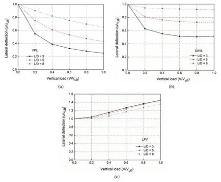
Figure 6:Influence of L/D ratio on the pile lateral deflection for(a)VPL case,(b)SAVL case and(c)LPV case considering different load application sequences
As can be seen from Fig.6b,the lateral deflection of the pile decreased with the increase of vertical load in the SAVL case,but less significantly than that in the VPL case.The most significant decrease in the lateral deflection occurred when vertical load increased from 0 to 0.2 Vult., showing that the smaller the L/D ratio,the more significantly the vertical load reduced the lateral displacement of the pile.At the vertical load level of Vult, pile with an L/D ratio of 3 experienced a decline in the lateral deflection by around 50%,compared with the 27%and 7%for the piles with aspect ratios of 5 and 8,respectively.
It can be seen from Fig.6c that the lateral deflection of the pile increased with vertical load at a constant rate in the LPV case.And it also shows that the smaller the L/D,the greater the increase of the lateral deflection under the the same proportion of vertical load.Piles with L/D ratios of 3 and 5 shared a similar trend in the increase of lateral deflection,slightly higher than that with an L/D ratio of 8.At the vertical load level of Vult, the lateral deflection of the piles with L/D ratios of 3 and 5 increased by approximately 42%,while that of the pile with an L/D ratio of 8 increased by 35%.
From the analysis above,it can be concluded that piles with smaller embedment depth were more sensitive to the change of vertical load amplitude.In the VPL and SAVL cases,the applied vertical load could produce confining effect on the surrounding sand,leading to an increase in sand stiffness while reducing lateral deflection and rotation thereafter.In the LPV case,extra lateral deflection would be induced by the applied vertical load due to thep-Δeffect.
3.3 The Underlying Effect Mechanism of Vertical Load on the Combined Loaded Monopiles in the VPL Case
The above analyses clearly indicate that the sequence of load application governs the lateral response characteristics of pile under combined load.In the offshore wind turbine projects,L/D ratio is generally less than 5,and VPL case is the most commonly seen in practice.The preceding discussion has proved that vertical load has a favorable effect on the lateral response of pile in the VPL case.To reveal its underlying mechanism,the variations of mean effective stresses and lateral effective stresses along the depth of the piles were extracted,as presented in Fig.7[25].The locations of selected stress points are illustrated in Fig.8.Stress points were located in front of the pile(at a distance of 0.01 m),relative to the loading direction,as shown in the figure.
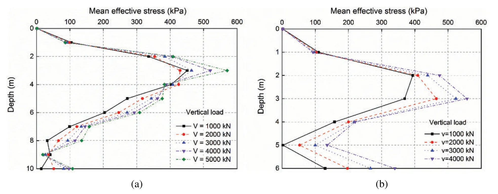
Figure 7: Variation of mean effective stresses (σm) along depth of piles in sand at L = 0.1D:(a)L/D=5 and(b)L/D=3
Figs.7a and 7b present plots of the mean effective stresses (σm) in the sand in front of the pile along the pile embedment for L/D=5 and L/D=3,respectively,showing that mean effective stress increases with the increase of vertical load,resulting in the increase of sand stiffness.
Figs.9a and 9b present plots of the lateral effective stresses (σxx) of the sand elements in front of the pile along the pile embedment for L/D=5 and L/D=3,respectively.It can be seen from the figures that the lateral effective stresses(σxx)in front of the pile were substantially higher under large vertical load,which could be be directly attributed to the increase in confining stress and sand stiffness as they could provide larger lateral stress along the frictional face.These findings are consistent with those obtained by Karthigeyan et al.[12].
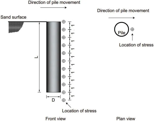
Figure 8:Schematic showing stress points along the embedment depth of the pile(unit:m)
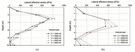
Figure 9: Variation of lateral effective stresses (σxx) along depth of piles in sand at L = 0.1D:(a)L/D=5 and(b)L/D=3
The increase in mean effective stresses(Δσm)caused by vertical load in the shallow sand layers was further illustrated by the shadings plots on the XZ-plane,as shown in Figs.10a and 10b for the piles with L/D ratios of 5 and 3,respectively.Herein,Δσmwas calculated by using mean effective stresses under vertical load of 2 MN to subtract the mean effective stress when the pile was under the initial condition(under zero vertical load).These shadings were extracted at the Y coordinate of 0.01 m.It is clearly seen that the mean effective stress of sand around the pile was higher in the presence of vertical load than that of both the piles under zero vertical load.
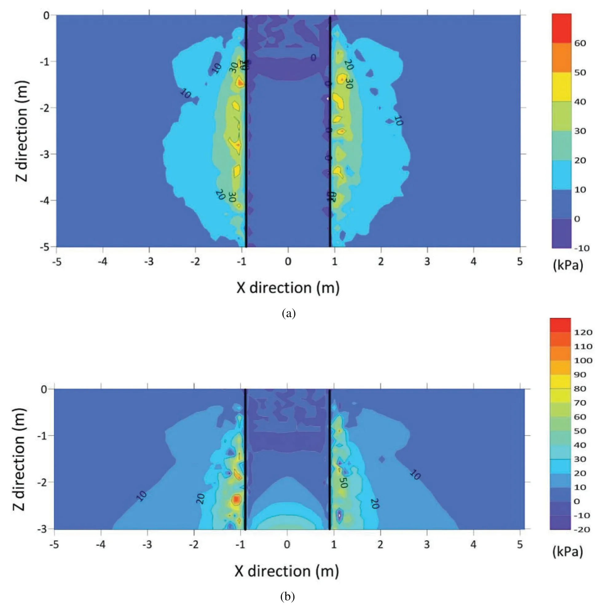
Figure 10: Increase of mean effective stress on the XZ-plane by applying vertical load of 2 MN: (a)L/D=5 and(b)L/D=3
Fig.11 shows the increase in mean effective stresses(Δσm)caused by vertical load on the XY-plane at the depth of 1.5D(2.7 m)for the piles with L/D ratios of 5(Fig.11a)and 3(Fig.11b),respectively.As can be clearly seen from the figures,the mean effective stress of sand around the pile was higher in the presence of vertical load.It is noticeable that under the same amount of vertical load,the increase of mean effective stresses(Δσm)on the pile with L/D ratio of 3 was about twice that for pile with L/D ratio of 5 due to the much smaller pile embedment.
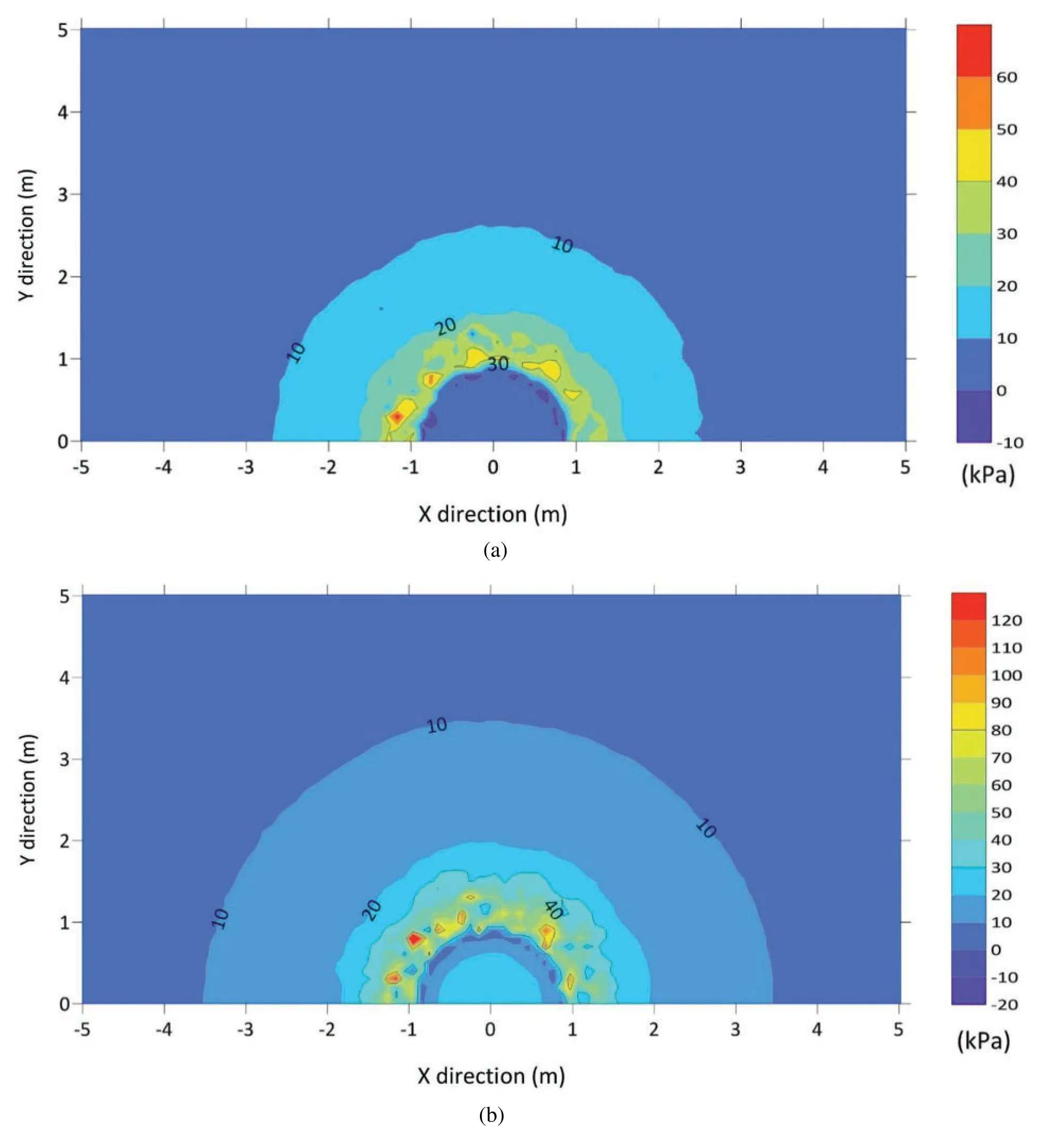
Figure 11: Increase of mean effective stress on the XY-plane by applying vertical load of 2 MN: (a)L/D=5 and(b)L/D=3(at depth z=1.5D)
4 Conclusions
The effect of vertical load on the combined load response of monopiles in marine sand is an important subject for correctly evaluating the performance of the offshore foundation.Threedimensional numerical analyses were conducted on piles under different loading sequences and with varying L/D ratios in this study.The following conclusions are drawn from the numerical results.
In the presence of vertical load, the lateral deflection of the pile in the VPL and SAVL cases decreases while it increases in the LPV case.Similar results were observed for piles with L/D ratios of 3,5 and 8.Taking the pile with an L/D ratio of 5 for example,under increased vertical load,the lateral capacity increases considerably in the VPL case(in the order of 13%to 45%),increases marginally in the SAVL case(in the order of 12%to 30%),but decreases marginally in the LPV case(in the order of-0.4%to-10%).The reason for increased lateral capacity under the action of applied vertical load in the common practical application case, namely, the VPL case, was examined by investigating the variation law in soil stress along the depth of the pile.The confining effect by vertical load increases means effective stresses in the soil around the pile,thus increasing soil stiffness and pile capacity.
When comparing the influence of L/D ratio on the lateral load-deflection behaviour under combined load,a similar trend was found among the three L/D ratios.Piles with a smaller embedment(L/D ratio)are more sensitive to the change of vertical load amplitude in the VPL and SAVL cases.In the LPV case,the effect of the slenderness ratio is not significant.In the VPL case,piles with L/D ratios of 3, 5 and 8 experience a decline in the lateral deflection by 75%, 56% and 35% respectively under the vertical load of V = Vult compared to that without vertical load.In the SAVL case, piles with L/D ratios of 3,5 and 8 witness a decline in the lateral deflection by 50%,27%and 8%respectively under the applied vertical load of V=Vult compared to that without vertical load.However,in the LPV case,the lateral deflection of piles with L/D ratios of 3,5 and 8 increases by 43%,43%and 36%respectively under the vertical load of V=Vult compared to that without vertical load.
The results in this paper suggest that the sequence of load application governs the subsequent deformation development of monopiles.It should be noted, however, that the loading sequences applied in this paper are physically inadmissible in practice,and thus in that sense,it is not appropriate to simultaneously apply the vertical and lateral load incrementally (as in the SAVL case).The application of this approach in this work shows that not only load combination and magnitude,but loading sequence needs to be properly modelled when investigating the effect of combined load on pile.A future study is planned to experimentally validate the findings of this paper.
Funding Statement:This work is funded by the section of Geo-Engineering, Delft University of Technology.
Conflicts of Interest:The authors declare that they have no conflicts of interest to report regarding the present study.
 Computer Modeling In Engineering&Sciences2023年4期
- Computer Modeling In Engineering&Sciences的其它文章
- A Study of BERT-Based Classification Performance of Text-Based Health Counseling Data
- Overview of Earth-Moon Transfer Trajectory Modeling and Design
- CEMA-LSTM:Enhancing Contextual Feature Correlation for Radar Extrapolation Using Fine-Grained Echo Datasets
- The Class of Atomic Exponential Basis Functions EFupn(x,ω)-Development and Application
- Corpus of Carbonate Platforms with Lexical Annotations for Named Entity Recognition
- Unique Solution of Integral Equations via Intuitionistic Extended Fuzzy b-Metric-Like Spaces