基于目标航迹的引导误差校正方法研究
2023-09-21 04:39路大举张大勇曾砾堂张凯杨浩张佩宇
应用光学 2023年5期
路大举,张大勇,曾砾堂,张凯,杨浩,张佩宇
(1.中国工程物理研究院 应用电子学研究所,四川 绵阳,621900;2.中国工程物理研究院研究生院,四川 绵阳,621900;3.中国工程物理研究院 流体物理研究所,四川 绵阳,621900;4.95972 部队,甘肃 酒泉,735300)
Introduction
The ATP is an important technical means to accurately track and point the target,but when the size of the detection target is small and is in the far distance,the field of view (FOV) of the photoelectric system becomes very small,which requires an effective prestage guidance to allow the target to fall into the FOV of ATP,then to achieve capturing,tracking and pointing.Effective pre-stage target guidance is the premise for the ATP to track and point the target[1-4].The essence of target guidance is a series of linear coordinate conversions,that is,the target point under the geodetic coordinate system can be converted into the local coordinate system of the ATP[5-7].Since a series of rotational and translational parameters will be introduced in this conversion process,the accuracy of these parameters will determine the ultimate target guidance accuracy.A guidance error correction method is proposed for the ATP based on unmanned aerial vehicle (UAV) track,which covers all the UAV track data from different positions around the ATP to solve optimal parameters for coordinate conversion in the process of computing target guidance data,thereby the target guidance accuracy is improved.The smaller the error of the pre-stage target guidance,the faster the target acquisition speed of ATP,which is of great significance for improving the corresponding speed of the target disposal.
1 Principles for target guidance
1.1 Target guidance scenario
As shown in Figure 1,the position of the target is expressed by the longitude,latitude and height in the geodetic coordinates,and the pointing of the ATP is expressed by the azimuth,pitch and slant distance in its local coordinates.The purpose of guidance is to make the FOV of ATP pointing to the target,and its process can be described as the conversion of the longitudelatitude-height position of target under the geodetic coordinates into the local coordinates of the ATP.
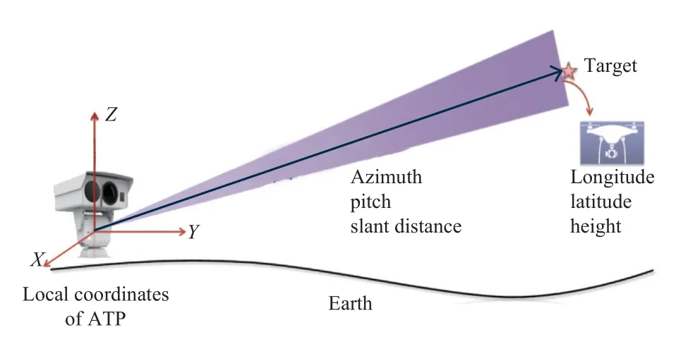
Fig.1 Schematic diagram of target guidance scenario
1.2 Target guidance mathematic model
As shown in Figure 2,the calculation process of target guidance data is divided into 4 steps during coordinate conversion[8-10].

Fig.2 Calculation process during coordinate conversion
The calculation process of each step is as follows.
1)Converting the geodetic position of the target into the earth-centered earth-fixed (ECEF) coordinates
The calculation process of converting the longitude (L),latitude (B),and height (H) into the ECEF coordinates is as shown in formula (1):
whererEis the radius of the long axis of earth,fis the flat rate of earth,and the values of which can be obtained by querying the WGS84 ellipsoid parameters.
The target position (Lt,Bt,Ht) and ATP position(Lz,Bz,Hz) are put into formula (1),respectively,and it is calculated to gain the target position (Xt,Yt,Zt) and ATP position (Xz,Yz,Zz) in the ECEF coordinates,then the target position is subtracted from the ATP position to obtain the target vector (X1,Y1,Z1) in the ECEF coordinates.
2)Converting the target vector into the flat earth coordinates
The calculation process of converting the target vector into the flat earth coordinates is as shown in formula (2):
whereTis the rotational matrix,and the rotational matrix around the (X,Y,Z) axis is as follows:
3)Converting the flat earth position of the target into the inertial navigation system (INS) coordinates
The calculation process of converting the flat earth position of the target into the INS coordinates is as shown in formula (3):
whereTis the rotational matrix,α,βandγis the azimuth,pitch and roll attitude angles of the INS measurement,respectively.
4)Converting the INS position of the target into the local polar coordinates of ATP
The calculation process of converting the INS position of the target into the local polar coordinates of ATP is as shown in formula (4) and formula (5),respectively.First,it is converted into the local rectangular coordinates of ATP by using formula (4),then it is converted into the polar coordinates by using formula (5):
where (X0,Y0,Z0) is the translation between the INS fix and the origin of the ATP coordinates,and (α0,β0,γ0) is the rotation between the INS and the ATP coordinates.
Where (A,E,D) is the local polar coordinate of the target position of ATP,Ais the target azimuth,Eis the target pitch,Dis the target distance,andE0is the pitch zero correction of the ATP.
2 Source of error
From the mathematical model of the guidance,we can see that the target guidance error sources are from the followings: the pre-stage target detection error,the position error of the ATP,the attitude angle error of the INS measurement,the calibration error of the installation relationship between the INS coordinates and the ATP coordinates (i.e.,installation error),and the pitch coder zero calibration error of the ATP (i.e.,pitch zero error)[4].
In addition,it takes time from the target detection to send the solved guidance data to the ATP,thus the ATP certain error is produced due to the delay of the received guidance data,and this error is called delay error.
In the above errors,the pre-stage target detection error,the position measurement error of the ATP,and the attitude position error of the INS measurement are determined by the inherent performance of the measuring equipment.The delay error is mainly affected by the delay of the system signal transmission.For a stable guidance system,the delay is generally more stable,and it can be obtained by the ATP time of receiving the guidance data minus the time of the target detection at the pre-stage,and compensated by deriving the guidance data.
The installation error and pitch zero error depend on the calibration method and the measurement accuracy of the calibration data.Therefore,it is mainly aimed to improve the guidance accuracy by studying the installation relationship between the INS coordinates and the ATP coordinates,as well as the pitch zero calibration method of the ATP.
3 Calibration of guidance parameters
3.1 ATP's pitch zero calibration method
As shown in Figure 3,the ATP's rotatingZ-axis andX-axis of the rotating plane form a rectangular coordinate system,where the pitch angleE' should be zero when the ATP's pointing is parallel with the rotating plane.However,when the ATP is installed,the actual pointing of its pitch coder's zero positionEcannot be coincided.Therefore,there will always be an errorE0.
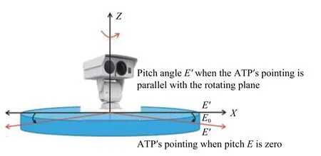
Fig.3 Schematic diagram of pitch zero error
Figure 4 shows the principle of the ATP's pitch zero calibration.First,the ATP is pointed to the target and a pitch valueE1,then the ATP is rotated by 180°around theZ-axis,the ATP's pitch angle is adjusted till after overhead and point to the target again,and another pitch valueE2is read at this moment.By geometric relationships,the calculation formula (6) for the ATP's pitch zero correctionE0can be established:

Fig.4 Schematic diagram of pitch zero calibration
This calibration method has a high accuracy of the ATP's pitch zero correction,which can be as high as an angle represented by one pixel unit of the ATP.
3.2 Calibration of installation relationship between INS and ATP
The ATP and the pre-stage detection system are required to simultaneously detect a moving UAV target,while let the UAV's flight tracks cover all the directions of the ATP as much as possible,and the target tracks detected by the ATP as well as that detected by the pre-stage detection system are recorded asP{A,E,D} andS,respectively.The formula (7) is used to obtain the target's track coordinateP' under the ATP's local coordinates,and the conversion of formula (1),formula (2) and formula (3) is used to obtain the target's track coordinateS'under the target's INS coordinates,whereS'is aN× 3 dimensional matrix[11-15].
The conversion betweenS'andP' is a rotational and translational relationship.Let θbe the conversional matrix,then the mathematical relationship betweenH'andP' is as shown in formula (8):
whereIis the unit vector of theN×1 dimension,H=[S′I],His theN×4 dimensional matrix,θis the conversional matrix of 4×3,and expressed as follows:
The first three lines of θare rotational parameters,the fourth line is a translational parameter.The rotational parameters in θcan also be expressed by(α0,β0,γ0)as follows:
Since the purpose of the guidance is to point the ATP to the target,the target trackPdetected by the ATP in the closed-loop can be used as a reference criterion for the guidance data solution.The calibration of installation relationship is the process of solving the parameters of conversion from the target's pre-stage detection trackSto the ATP's detection trackP.Therefore,the calibration of installation relationship can be converted to a math problem of solving the optimal conversional matrixθin formula (8).
The smaller the difference of target position data between the target guidance data and ATP detection,the higher guidance accuracy.Based on this principle,we useJ(θ) to measure the guidance error,which can be expressed as formula (9):
whereJ(θ) is a secondary function of θ,and the math problem can be simplified as solving the θwhenJ(θ)is minimum.Expanding formula (9),we have:
The derivativeθis substituted into formula (10) to obtain:
When the derivative is zero,the value ofJ(θ) is minimum,so the optimalcan be solved.
For the rotational and translational conversion parameters obtained through this method,because the solution process uses a large number of UAV track points covering all the directions around the ATP to fit the calculation,the random error of the pre-stage detection and the ATP has less impact on.Therefore,the obtained installation relationship parameters between the INS and the ATP has a considerably high accuracy.
4 Validation experiment
4.1 Experimental design
As shown in Figure 5,the device used for the experiment was mainly composed of 5 parts: the ATP,the INS,a UAV,a radio station,and a control system.
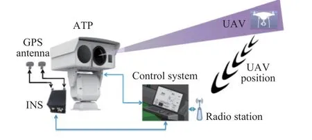
Fig.5 Schematic diagram of experimental device
The ATP was used to track and point the flying UAV and acquire the UAV's flight track.The INS is used to measure the geodetic coordinates of the experimental device and the ATP's azimuth,pitch,and roll attitude relative to the horizontal coordinates.As the target for detection,the UAV flied around the ATP,and at the same time,its own position data was transmitted to the control system via the radio station as the position for pre-stage detection.The main function of the control system was to guide the ATP to track and point the UAV,and record the ATP's tracking and pointing tracks,the UAV's track,and the position and attitude data measured by the INS.
The experimental site was selected at an unobstructed open area.The UAV should change its height and distance during flight to avoid its track being in a near-same plane.
4.2 Experimental results
Referring to the ATP's pitch zero calibration method described in section 3.1,when the ATP pointing at the static target,we read the pitch angleE1=0.9°.Then the ATP was horizontally rotated by 180°,the pitch angle was adjusted till after overhead and pointed to the same point of target again,and the pitch angleE2=180.3° was read.The formula (6) was used to calculate and obtain the corrected value of the pitch zeroE0=0.6°.
During the calibration experiment of the installation relationship between the INS and the ATP,the frequencies of the acquired pre-stage detection data of the target and the ATP's detection data were both 20 Hz,the flight time of the UAV was about 23 min,and 11 000 sets of valid data were acquired from the flight track.The valid data was defined when the prestage detection data of the target was normal and the ATP was in a closed-loop state with respect to the target.In this section of valid data,the UAV's flight track was as shown in Figure 6,where the circle was the position of the ATP,and the curve was the UAV's flight track.
The longitude,latitude,and height of the ATP's position measured by the INS were [104.731 95°,31.530 62°,550.24 m],respectively.The azimuth,pitch,and roll attitudes of the ATP relative to the horizon when measured in static conditions were[317.93°,-0.08°,1.12°],respectively.Based on the above data and using the installation relationship calibration method described in section 3.2,the direct rotational and translational parameter matrixof the INS and the ATP coordinates was calculated and obtained as follows:
The target pre-stage detection data,the position and attitude data measured by the INS,and the above calibration values were put into the guidance mathematical model described in section 1.2,and the difference between the guidance data and the target data directly detected by the ATP was calculated to obtain the guidance error.The azimuth and pitch guidance errors were as shown in Figure 7,and the target azimuth and pitch velocity were as shown in Figure 8.It could be seen from Figure 7,the horizontal lines that the standard variance of azimuth guidance was less than 0.052°,the standard variance of pitch guidance was less than 0.04°,and the maximum guidance error was 0.7°.
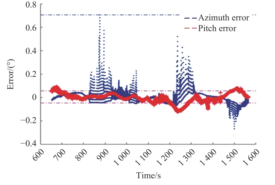
Fig.7 Azimuth and pitch error curves of guidance data

Fig.8 Azimuth and pitch angular speed curves of target
Comparing Figure 7 and Figure 8,we could see that the larger guidance errors occurred at the positions where the absolute azimuth angular speed of the target was larger.The azimuth angular speed represented the tangential level flight speed of the target.The reasons for this condition were the delay error and the target's position error became large.The faster the target's speed,the more prominent the guidance delay caused by the delay error.Comparison of Figure 7 and Figure 8 indicated that,when the target's azimuth angular speed was at 0.8°/s,the guidance error was no greater than 0.7°.Accurate estimation of the delay and target track prediction algorithm could reduce the error caused by data transmission delay.
5 Conclusion
In regard to the problem of the ATP's pre-stage guidance error correction,this paper suggests a guidance error correction method based on the target's flight track.This method uses the UAV's track data and the least square method to estimate the optimal guidance data transfer parameters,thus reducing the effect of the target's pre-stage detection and the ATP's random error on the calibration process,and obtaining highly accurate target guidance calculation parameters.On the experimental device set up for this study project,we can achieve that the azimuth guidance accuracy is better than 0.052° (variance),the pitch guidance accuracy is better than 0.04° (variance),and the maximum guidance error is no more than 0.7° when the target's speed is 0.8°/s.For the problem of increased guidance error when the target's angular speed relative to the ATP is larger,the follow-on study will be carried out on the target track prediction method,with the aim to reduce the effect of delay errors on the guidance accuracy.
猜你喜欢
军工文化(2023年3期)2023-04-28
作文周刊·小学二年级版(2022年44期)2022-11-29
含能材料(2022年7期)2022-07-13
四川大学学报(自然科学版)(2021年5期)2021-10-18
软件(2020年3期)2020-04-20
传感器世界(2019年9期)2019-03-17
水动力学研究与进展 B辑(2018年3期)2018-07-06
金色年华(2016年10期)2016-02-28
创业家(2015年6期)2015-02-27
创业家(2015年6期)2015-02-27