
Large spatial shifts of reflected light beam off biaxial hyperbolic materials
2023-12-02 09:22JiaGuoShen沈加国SyedulhasnainBakhtiar哈思内恩HaoYuanSong宋浩元ShengZhou周胜ShuFangFu付淑芳XuanZhangWang王选章XuanWang王暄andQiangZhang张强
Chinese Physics B 2023年11期
Jia-Guo Shen(沈加国), Syed-ul-hasnain Bakhtiar(哈思内恩), Hao-Yuan Song(宋浩元), Sheng Zhou(周胜),Shu-Fang Fu(付淑芳),,†, Xuan-Zhang Wang(王选章), Xuan Wang(王暄), and Qiang Zhang(张强),‡
1Key Laboratory for Photonic and Electronic Bandgap Materials,Chinese Ministry of Education,and School of Physics and Electronic Engineering,Harbin Normal University,Harbin 150025,China
2School of Integrated Circuits,Engineering Research Center for Functional Ceramics,Wuhan National Laboratory for Optoelectronics,Huazhong University of Science and Technology,Wuhan 430030,China
3Key Laboratory of Engineering Dielectrics and Its Application,Ministry of Education,Harbin University of Science and Technology,Harbin 150080,China
Keywords: Goos–H¨anchen shift,Imbert–Fedorov shift,α-MoO3
1.Introduction
A number of studies have shown that when a paraxial light beam interacts with the surface of the materials under specific conditions,the reflective beams show a relatively small shift from their geometrically/symmetrically incidence position.[1,2]The shift that occurs in the plane of the incoming light is referred to as the Goos–H¨anchen(GH)shift,which was first observed by Goos and later confirmed experimentally by H¨anchen.[3,4]While the shift normal to the plane of incident light is called the Imbert–Fedorov (IF) shift,[5,6]which further originates from the spin–orbit interaction of incident light.[7]The GH shift length is usually nearly the vacuum wavelength when the light–beam interacts with the conventional dielectrics, while the IF shift only indicates a small fraction of the vacuum wavelength.[2,8]It has been observed that the GH shift (in the case of the total internal reflection) is highly related to the medium-anisotropy.[3,5]Because of their excellent performance in micro-nano optics and device technology, these two phenomena have aroused wide interest of researchers.They used several materials to improve the spatial shifts of reflected light beam on the material surface, starting with the original work on isotropic and anisotropic mediums, such as the polar crystal,[9]photonic crystals,[8,10]metamaterials,[11]metasurfaces,[12]topological material,[13]magnetic media,[14]and quasibound states in the continuum.[15,16]When facing a small GH shift and IF shift,the quantum weak measurement can be used to detect this phenomenon veraciously, since it uses the precise measurement of the physical parameters of the material, such as dielectric function and permeability.[17]It accurately captures the shift produced on the surface of the material, opening up a broad window for the potential application of IF and GH shifts in sensing technology.
Hyperbolic materials (HMs) are materials with hyperbolic isofrequency contours, featuring having both positive sign and negative sign in their principal components of the dielectric permittivity tensor.[18–20]These materials have been utilized in various areas,including negative refraction,[21]hyperlens effect,[22]thermal emission engineering,[23]and other novelty optical devices.[24,25]Traditional HMs are based on meta-materials, which require careful design of the cells that make up a unit to obtain the characteristic hyperbolic permittivity tensor.[11]Despite the potential benefits of these strategies, their implementation poses significant challenges due to the complex and precise nano-fabrication and lithography processes required to create a unit cell that can effectively manipulate light waves.Moreover, for the effective medium approximation to be valid, the unit cell must be considerably smaller than the wavelength of light.As a result, researchers have turned to explore natural biaxial hyperbolic material (NBHM), which possesses structural anisotropy resulting in hyperbolic permittivity without the need for lithography techniques.[26,27]For example,hexagonal boron nitride(hBN)has remarkable optical performance, featuring extremely low loss and two hyperbolic reststrahlen bands (HRBs) in the infrared range.[28,29]However, owing to its uniaxial optical response, it is unsuitable for in-plane anisotropy.On the other hand,α-molybdenum trioxide (α-MoO3) exhibits phonondriven NBHM behaviour in the long-wavelength mid-infrared range, making it a promising candidate for creating optical components with superior efficiency.[30,31]
α-MoO3,a type of van der Waals crystal with orthorhombic unit cells, shows a biaxial hyperbolic anisotropy in the mid-infrared part of the electromagnetic spectrum.[32,33]The inherent anisotropy ofα-MoO3, arising from its distinctive crystalline structure, results in natural in-plane hyperbolic characteristics that stem from the interplay between the lattice modes and three crystal directions that are orthogonal to each other.Thus,this presents a novel possibility in the utilization of photonic tools that rely on the angle-dependent polarization,and opens the way for exploring polarization-based filters and reflectors.[34,35]Scholars have discovered thatα-MoO3possesses various unique physical phenomena and applications.Huet al.[36]documented the identification of both topological polaritons and photonic magic-angle in bi-layeredα-MoO3.Dereshgi and colleagues introduced a new approach to constructing IR polarization converters by usingα-MoO3flakes,which does not involve lithography and purely relies on the use of orthogonal in-plane phonons.[37]
In this paper, we take the advantages ofα-MoO3biaxial hyperbolicity and strong in-plane anisotropy to achieve an effective improvement of spatial shift.Meanwhile, we utilize the hBN as a substrate.As a natural hyperbolic material, the reststrahlen bands (RBs) of hBN partly overlap the RBs ofα-MoO3, and both the two hyperbolic materials exhibit hyperbolic dispersion characteristics in their frequencyresponse regions.Therefore,compared with ordinary isotropic and anisotropic materials,the hBN has a great ability to modulate the beam shifts.
2.Theoretical description
The setup comprises two distinct components:the surface layer,i.e.,theα-MoO3film with thickness denoted byd,and the substrate that is a semi-infinite hBN crystal with its optical axis(OA)perpendicular to its surface.The schematic diagram of coordinate system and configuration can be found in Fig.1,which shows that the orientation of the structure’s surface is aligned with thex–yplane,while the plane of incidence is situated in thex–zplane.a,b,andcdenote the[100],[010],and[001]principal-axis directions ofα-MoO3, respectively.Theaaxis lies in the surface plane atθrelative to thexaxis,whereθcan also be used to indicate the orientation of the incident plane.A Gaussian beam incident on the surface at angleβproduces the shifts of reflected beam along thexaxis andyaxis,called GH and IF shifts,respectively.

Fig.1.Schematic illustrating geometry and coordination system, with β denoting the incident angle, θ the angle between incident plane and a–b plane,and d the thickness of α-MoO3 layer.
In theo–abccoordination system, the dielectric permittivity ofα-MoO3crystal is a diagonal matrix with elementsεa,εb, andεc, which is an important characteristic of biaxial hyperbolic crystal.Nevertheless, the effective permittivity in theo–xyzcoordinate system can be defined as
whereεxx=εacos2θ+εbsin2θ,εyy=εbcos2θ+εasin2θ,andεxy=(εb-εa)cosθsinθ.The three dielectric constants can be collectively expressed as[19,38]
The permittivity tensor is denoted byεj, whileε∞,jrefers to the dielectric constant at high frequencies.In addition,there are damping constantΓj,longitudinal optical phonon frequencyωLO,j,and transverseωTO,joptical phonon frequency which are associated with the system.The parameters used in Eq.(2)are reproduced from Ref.[30].
For theα-MoO3layer,the induced electric field satisfies the following equation(based on Maxwell equations):
wheref=µ0ε0ω2.Equation (3) has nontrivial solutions only when the det(M)=0,it provides the well-known Fresnel’s equation for biaxial medium,a quadratic equation,in the squaredzcomponent of the wave vector,kz,which is the two wave branches in theα-MoO3.Its solutionskzread as

where superscript I represents the incident light and R represents the reflection light, where the common factor exp(ikxx-iωt) is omitted for simplicity,koandkedenote the usual light wave vector and unusual light wave vector in the hBN,respectively.Meanwhile,the magnetic fields can be achieved with the Maxwell equation in the different spaces.Subsequently, the boundary conditions are introduced, which stipulate that the in-plane segments of the magnetic field and electric field must be seamless across the film’s surface, located atz=0 andd.The electric field’s amplitude is determined by
with

The amplitude of the electric field for the transverse electric (TE) wave with s-polarization is represented byERy,while in the reflected beam, the two components of the field amplitude for the transverse magnetic (TM) wave with ppolarization are denoted byERxandERz.The reflective electric field is expressed as a matrix form in theo–xyzcoordinate system.To resolve the GH shift and IF shift in the reflective beam,it is essential to employ rotational transformations on both the incident and reflective central waves.According to the geometric correlation, the transformation relationship between the incident electric field and reflected electric field can be obtained as follows:EIx=EIpcos(β),EIy=EIs,EIz=-EIpsin(β),ERp=-ERxcos(β)-ERzsin(β),ERs=ERy,andERz=cot(β)ERx.As result,the correlation equation for the incident field and reflective field in the beam coordinate system can be written as
The subscripts “s” and “p” indicate the s-polarization and ppolarization of the incident and reflected central waves, respectively.While the results mentioned earlier are obtained by using the central plane wave; if we consider the paraxial wave,the incident beam is limited to a narrow range of plane waves around the central wave in momentum space.We assume the incident beam to be a Gaussian beam,which does not comply with the law of reflection Eq.(8)and provides two indications: firstly,the use ofα-MoO3results in a non-diagonal matrix relationship between the incident electric field and reflected electric field, and secondly, all elements of the reflection coefficient matrix are dependent onθandβ.If this arises from the anisotropy of theα-MoO3layer,it can be anticipated that the GH and IF shift may exist for a linearly-polarized incident beam.In this case, the expression for the GH shift should be derived.To do so, we can expand the elements of the coefficient-matrix to the first order ofβpin Eq.(8) and solely considerβpwhile ignoringθs.The relative reflection may be expressed as
First,We focus our attention on deriving the IF shift formula.The polarization orientation of the incident or reflected beam is directly changed by a slight adjustment in the incident plane’s orientation.The matrix components in Eq.(8),where onlyθsis considered andβpis omitted,are also affected.For smaller rotationθs,the reflected electric field can be written as

If the surface layer and substrate are replayed by an isotropic material, the matrix elements of Eq.(8) will becomea12=a21=0,a11=-fp, anda22=fs(wherefpandfsare the reflective coefficients of the p and s waves).For the highsymmetry configurations(θ=0,90◦),the same results can be obtained:a12=a21=0,a11=-fp, anda22=fs.Likewise,the expression of GH and IF shifts in the isotropic medium can be obtained with the same method.Consequently, equations(10)and(12)can be simplified into a well-known result,which is cited from Ref.[1].
3.Numerical calculations and discussion
To find out the spatial shift of the surface of theα-MoO3crystal,we first illustrate the permittivity of the monolayerα-MoO3crystal as depicted in Fig.2(a),whereεa,εb,andεcrepresent the three elements of dielectric permittivity ofα-MoO3crystal in thea,b,andcdirections,respectively.If there exists an frequency interval where the signs of dielectric functions are opposite,this frequency interval is called an HRB.For the NBHM,if one element has a positive dielectric function value and the other two elements have negative dielectric function values, it is called a type-II hyperbolic material, otherwise it is a type-I hyperbolic.Therefore,we can see the five HRBs ofα-MoO3with different colors,as listed in Table 1.
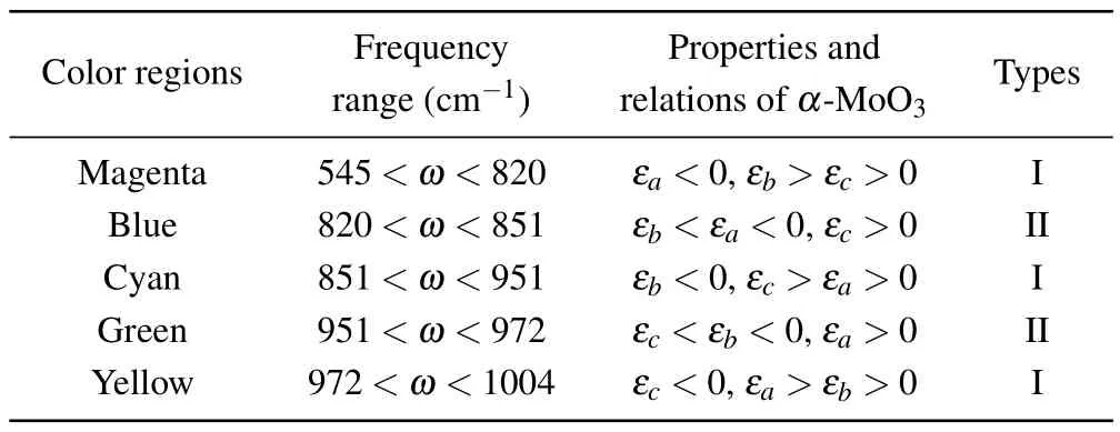
Table 1.Frequency regions, properties and relations among εa, εb, and εc of types α-MoO3.
The physical parameters of the hBN crystal are presented in Ref.[11].Its permittivity values are illustrated in Fig.2(b),where the red part corresponds to the HRB-I, and the green part refers to the HRB-II.Furthermore, we can observe that the HRB-I of hBN and the second HRB ofα-MoO3partly overlap in a frequency response space.Both materials exhibit unique properties in this common region,so we will focus our attention on this area.
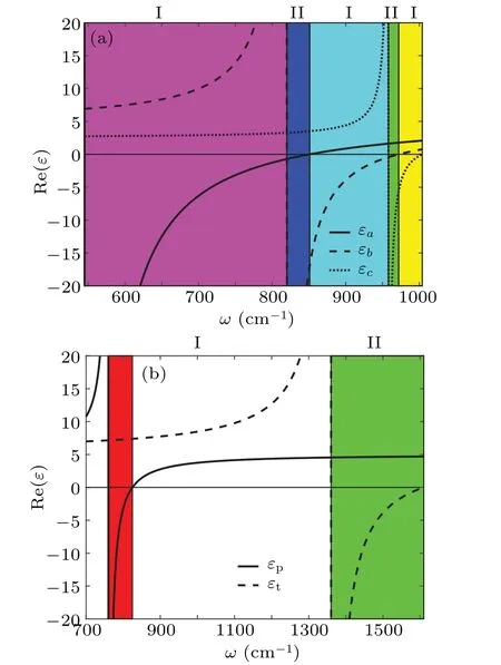
Fig.2.(a)Permittivity of monolayer α-MoO3,with solid,dashed,and dotted lines denoting the permittivity in different crystal directions,and different areas relating to different HRBs.(b) Permittivity of the bulk hBN, with solid and dashed lines referring to the permittivity parallel and vertical to OA, and red and green areas indicating HRBs respectively.
To comprehend the shift spectrum in the reflected beam spectra,it is necessary to revisit the reflection and transmission that occur at the interface between air and an isotropic polar crystal with a relative permittivityε.Whenkzbecomes imaginary,the total reflection is observed,and the transmitted wave transforms into an evanescent wave.Then,the critical angle is determined by the equation sin2βc=ε,where 0<ε<1.The Brewster angle can be determined byRp=0.For the present structure,a similar definition for the critical or Brewster angle can still be achieved.
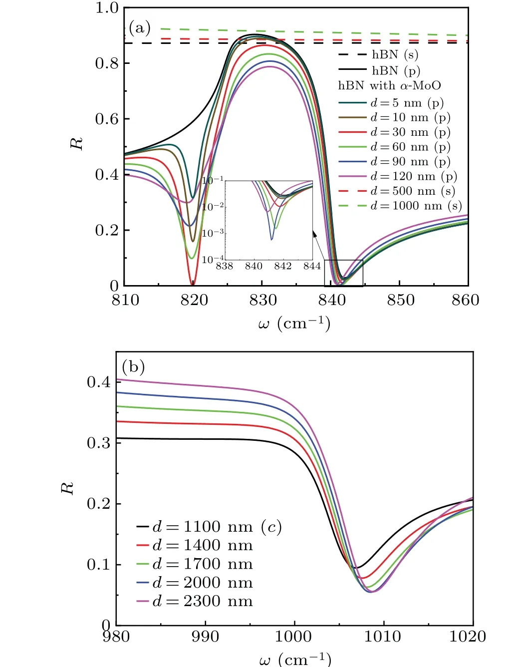
Fig.3.Curves of reflectivity corresponding to (a) linearly-polarized incident beam and (b) circularly-polarized incident beam at different frequencies and thickness values of α-MoO3.In panel (a), the green dashed line is related to the s-polarization incident beam,and the solid line corresponds to the p-incident beam.The inset illustrates the reflective ratio when d<30 nm for p-polarized incident beam.
Figure 3 shows the curves of reflectance of the ppolarized, s-polarized, and circularly polarized beams.The black solid line or dash line in Fig.3(a) indicates the reflectivity of the surface of semi-infinite hBN material without theα-MoO3film for p-or s-polarized incident beam.It is not difficult to find that the reflectivity of p-polarized incident beam changes significantly with frequency, while the reflectivity of s-polarized incident beam remains basically unchanged.After placing theα-MoO3film on hBN, two dips are observed atω ≈820 cm-1and 840 cm-1, respectively.In addition, the reflectivity of p-polarized incident beam approaches to zero atω ≈840 cm-1,where the incident angle should be the Brewster’s angle.Normally,the spatial shifts,such as GH shift and IF shift,can be enhanced greatly at critical angle or Brewster’s angle.[12]An inset about the reflectivity atω ≈840 cm-1is plotted in order to further examine the effect of the thickness ofα-MoO3film on the reflectivity.It is clear to find that the reflectivity will be larger than 1% once the the thickness ofα-MoO3film is less than 30 nm.It can be predicted that if the larger GH or IF shift is expected,the thickness ofα-MoO3film should be larger than 30 nm.On the other hand,the reflectivity for s-polarized incident beam remains unchanged with the frequency even if theα-MoO3film is placed on the surface of hBN,while the reflectivity increases slightly with the thickness ofα-MoO3film increasing.Comparing with Fig.2(b),it also can be found that the permittivity of hBNεpis just equal to 1.0 atω ≈40 cm-1for p-polarized incident beam,which is located near the epsilon being nearly zero of HRB-I.Therefore,we will focus our attention on the GH or IF shift of p-polarized incident beam in the following discussions.Figure 3(b) displays the curves of reflectivity of leftc-polarized incident beam forα-MoO3films with different thickness values.Only one dip appears atω ≈1007 cm-1where the reflectivity gradually decreases with the increase ofα-MoO3film increasing.
Initially, we concentrate on two highly symmetric configurations, namely, geometry-I (θ=0◦) with theaaxis ofα-MoO3along thexaxis,and geometry-II(θ=90◦)with theaaxis perpendicular to thexaxis.For the highly symmetric configurations,εxy=0 in Eq.(4) which leads to an analytical expression fork±.k2±=εyy f2-k2xfor s-polarized incident beam andεzzk2±=εxxεzz f2-εxxk2xfor p-polarized incident beam.In geometry-I,εxx=εa,εyy=εb,and in geometry-II,εxx=εb,εyy=εa.Figure 4 illustrates the curves of GH shift versus frequency for the different thickness in the geometry-I and geometry-II.The GH shift on the surface of hBN is presented in Fig.4(a), which is about 5λ0atω=841.5 cm-1.With the increase of the thickness ofα-MoO3film,the influence of thickness on GH shift becomes more pronounced.The GH shift reaches a negative maximum value of about 39λ0atd=90 nm.Of course,if the positive GH shift is required we have to consider the situation atd=120 nm.The corresponding frequency is located on the left border of the overlapping region of HRBs.In Fig.4(b),a noticeable peak for GH shift is present in geometry-II,where a maximum GH shift can reach 86λ0and rapidly changes from negative to positive.It further proves that the GH shift can be enhanced significantly at the Brewster angle since a phase gradient of the corresponding reflection coefficient will experience a sharp variation due to the high in-plane anisotropy.For both geometries,it can be found that the GH shift generated on the the surface ofα-MoO3-hBN is much larger than the one excited on the surface of the semiinfinite hBN.As is well known,according to the discussion of Eq.(12)the IF shift cannot be generated for linearly polarized incident beam at the interface between two isotropic media.However,theα-MoO3layer leads to the off-diagonal relationship between the incident electric field and reflective field as demonstrated in Eq.(9).We can predict that the IF shift will be generated not only by the circularly polarized beam but also by the linearly polarized beam,which is caused mainly by the in-plane anisotropy ofα-MoO3layer.In order to investigate the IF shift for p-polarized incident beam, we illustrate the variation of IF shift in theθ–ωplane atβ=12◦as shown in Fig.4(c).It is obvious that the larger IF shift exits in the region of 13◦<θ<50◦where the incident frequency is fixed at about 825 cm-1.Moreover,the largest IF shift can be about 0.07λ0atθ=33◦.Whenθ=0◦and 90◦,the off-diagonal elements of the reflection coefficient matrix become zero, which will cause the reflected beam to become a single s-or p-polarized beam.Thus, the IF shift still cannot be observed at the two highly symmetric structures, which can also be illustrated by Fig.4(c).

Fig.5.Curves of IF shift of reflective beam of α-MoO3 with various thicknesses in HRBs in(a)geometry-I and(b)geometry-II for the circularly polarized incident beams with β =12◦.
In the previous discussion, we described in detail the GH and IF shifts of p-polarized incident beam.Generally speaking, the generation of IF shift is attributed to the conservation of spin–orbit angular momentum.Therefore, we choose the left circularly-polarized incident beam to simulate the IF shift.In Fig.5, the peak of the IF shift can be seen atω=1007 cm-1, corresponding toεc=0.In addition, as the thickness ofα-MoO3increases,the maximum value of the IF shift first increases and then decreases.Whend=1700 nm,the maximum IF shift can reach about 2.7λ0.This pattern can also be seen in geometry-II as shown in Fig.5(b).When the thickness is 900 nm, the peak of the IF shift is about 1.4λ0.In order to analyze the peak of the IF shift,which is taken for example,we simulate the reflectivity of the s-and p-polarized incident beams in geometry-II whend= 900 nm, which is shown in the inset of Fig.5(b).A dip ofRpis observed which just intersects withRsatω=1007 cm-1.Based on the discussions in Ref.[11],the conditions reaching the maximum value of IF shift should be satisfied at this frequency.
4.Conclusions
To sum up, our investigation focuses on analyzing the shift of the reflected beam from theα-MoO3with a finite thickness on a bulk hBN substrate.We observed that the interplay between anisotropic hyperbolic polaritons inα-MoO3plates and hBN crystal results in intricate changes in the GH and IF spectra.They are not like the reflected beam from the bulk hBN crystal surface nor the infinite thicknessα-MoO3surface.Especially for geometry-II, the GH shift can reach 86λ0withd=90 nm, which lies in the Brewster angle.By comparing the GH shift of the added MoO3flakes with that of the semi-infinite hBN structure,adding MoO3flakes with a certain thickness can effectively increase the GH shift of the surface in this frequency interval.For the circularly-polarized incident beam,the IF shift is 2.7λ0when the NBHM thickness is 1700 nm.Meanwhile,both materials are NBHM,which are easier to prepare and have simpler structures.These findings pave the way for future research into modulating the GH and IF shifts,which can be used to create novel micro-optical devices and biosensors.
Acknowledgements
Project supported by the Natural Science Foundation of Heilongjiang Province, China (Grant No.LH2020A014),the Fund from the Education Commission of Heilongjiang Province, China (Grant No.2020-KYYWF352), the Fund from the Key Laboratory of Engineering Dielectrics and Its Application (Harbin University of Science and Technology),Ministry of Education, China (Grant Nos.KFM202005 and KF20171110), and the Harbin Normal University Postgraduate Innovative Research Project,Heilongjiang Province,China(Grant Nos.HSDSSCX2022-53 and HSDSSCX2022-49).
猜你喜欢
Chinese Physics B(2022年4期)2022-04-12
看世界·学术上半月(2020年1期)2020-09-10
甘肃农业(2020年2期)2020-03-19
文萃报·周二版(2019年31期)2019-09-10
艺术评论(2018年3期)2018-05-16
校园英语·下旬(2017年13期)2017-12-27
甘肃农业(2017年1期)2017-03-03
棋艺(2016年4期)2016-09-20
中国卫生(2015年7期)2015-11-08
中国卫生(2014年6期)2014-11-10

- Chinese Physics B的其它文章
- Optimal zero-crossing group selection method of the absolute gravimeter based on improved auto-regressive moving average model
- Deterministic remote preparation of multi-qubit equatorial states through dissipative channels
- Direct measurement of nonlocal quantum states without approximation
- Fast and perfect state transfer in superconducting circuit with tunable coupler
- A discrete Boltzmann model with symmetric velocity discretization for compressible flow
- Dynamic modelling and chaos control for a thin plate oscillator using Bubnov–Galerkin integral method