Development of underwater electric manipulator based on interventional autonomous underwater vehicle (AUV)
Xiaohui HU, Jiawang CHEN,3, Hang ZHOU, Ziqiang REN
Research Article
Development of underwater electric manipulator based on interventional autonomous underwater vehicle (AUV)

1Ocean college, Zhejiang University, Zhoushan 316021, China2Hainan Institute, Zhejiang University, Sanya 572025, China3The Engineering Research Center of Oceanic Sensing Technology and Equipment, Ministry of Education, Zhoushan 316021, China
In applications such as marine rescue, marine science, archaeology, and offshore industries, autonomous underwater vehicles (AUVs) are frequently used for survey missions and monitoring tasks, with most operations being performed by manned submersibles or remotely operated vehicles (ROVs) equipped with robotic arms, as they can be operated remotely for days without problems. However, they require expensive marine vessels and specialist pilots to operate them. Scientists exploring oceans are no longer satisfied with the use of manned submersibles and ROVs. There is a growing desire for seabed exploration to be performed using smarter, more flexible, and automated equipment. By improving the field operation and intervention capability of AUVs, large-scale and long-range seafloor exploration and sampling can be performed without the support of a mother ship, making it a more effective, economical, convenient, and rapid means of seafloor exploration and sampling operations, and playing a critical role in marine resource exploration. In this study, we explored the integration technology of underwater electric robotic arms and AUVs and designed a new set of electric manipulators suitable for water depths greater than 500 m. The reliability of the key components was analyzed by finite element analysis and, based on the theory of robot kinematics and dynamics, simulations were performed to verify the reliability of the key components. Experiments were conducted on land and underwater, trajectory tracking experiments were completed, and the experimental data in air and water were compared and analyzed. Finally, the objectives for further research on the autonomous control of the manipulator underwater were proposed.
Underwater electric manipulator; Inverse kinematics; Trajectory planning; Trajectory tracking accuracy
1 Introduction
In applications such as marine rescue, marine science, archaeology, and the offshore industries, autonomous underwater vehicles (AUVs) are frequently used for survey missions and monitoring tasks, with most operations being performed by manned submersibles or remotely operated vehicles (ROVs) equipped with robotic arms (Paull et al., 2014). Although researchers have recently opened the door to future interventional AUVs, there is still a long way to go before autonomous underwater interventions are possible (Ridao et al., 2015). The field of underwater intervention can be traced back as far as the 1990s when the UNION project validated coordinated control and sensing strategies to improve the autonomy of interventional ROVs under simulated conditions (Rigaud et al., 1998). During the same period, the European AMADEUS project conducted coordinated control experiments with two 7-degree-of-freedom (DOF) manipulators in a water tank. The European SWIMMER project proposed a hybrid system that worked by transferring AUVs to the seafloor via ROVs (Evans et al., 2001). The British ALIVE project investigated the autonomous docking system (Evans et al., 2003), autonomous navigation, and other functions of interventional AUVs, and conducted simulation experiments (Han and Chung, 2008).
Most of the aforementioned studies conducted simulated or actual experiments in a simplified environment, with few reports of actual setups (Leonessa, 2008). In recent years, AUVs with multi-DOF manipulators have increasingly attracted attention. Some of the relevant studies are worth mentioning, such as the SAUVIM project of the University of Hawaii, USA, which realized the experiments of a manipulator–AUV system equipped with 7-DOF manipulators for autonomous recovery of submarine targets (Marani et al., 2009), and the C-Manipulator project of Germany, which proposed a vision-based underwater electric manipulator design scheme and developed an experimental platform to simulate unmanned underwater vehicle operations (Spenneberg et al., 2007). In recent years, Spain's GIRONA 500 has experimented with various manipulator models and achieved interesting results (Fernandez et al., 2013).
This study presents a new type of underwater electric manipulator designed (although not limited) to be integrated into a new AUV, built under the auspices of the Zhejiang Provincial Key R&D Project "Development and Demonstration Application of a Cableless Robot for Operational Subsea Pipeline Inspection". The objective is to build an underwater vehicle-manipulator system (UVMS) with a dedicated underwater electric manipulator to perform tasks such as autonomous inspection of, and autonomous intervention on, subsea pipelines.
This article describes a prototype underwater electric robotic arm and conducts simulation and experimental work to verify its feasibility and identify the strengths and weaknesses of its design and control system for further improvement in subsequent research. Section 2 of the article presents the architecture of the underwater robotic arm, including the robotic arm, the connection to the AUV, the vision subsystem, and the newly designed gripper, with finite element stress analysis of the reliability of key components, culminating in the presentation of the overall physical prototype of the robotic arm and a schematic of its integration with the AUV. Section 3 performs motion simulation based on the kinematics and dynamics theory of the robotic arm using the MATLAB toolbox. In Section 4, experiments on trajectory tracking and motion control of the robotic arm in air and water are conducted, and the experimental data are compared and analyzed to provide the conditions for further research on the autonomous control of the robotic arm underwater. Finally, Section 5 provides some conclusions, and presents objectives for subsequent research.
2 Architecture of the underwater manipulator
The object of this project is to design and build an autonomous UVMS capable of autonomous underwater suspension operations. As part of the project, a robotic arm, which can be mounted on the AUV and operate autonomously underwater, is the goal. The design of the overall structure of the manipulator is described in detail, including the design of the manipulator configuration, the waterproof structure, and the AUV connection mechanism.
2.1 Manipulator structure design
The electric manipulator designed and mounted on the AUV has four DOFs, as shown in Fig. 1. Three rotary joints are driven by three joint motors to control the (,,) position of its end-effector, while a fourth actuator controls its roll. Full attitude control of the end-effectors can only be achieved through the coordinated movement of the arm and AUV. The different functional end-effectors can be interchanged to accommodate different interventions.

Fig. 1 Underwater five-function electric manipulator
The robotic arm is designed with four DOFs for three reasons:
1. The arm is mounted on the AUV and is powered entirely by the AUV's battery. In order not to affect the overall range of the AUV, light weight and low-power consumption are basic requirements for the design of the arm. The small DOF also means that the number of joint motors is reduced, which helps reduce power consumption.
2. With three DOFs, the manipulator can control its end-effector to reach any point in its working space. Compared with six DOFs, which enable the end-effector to reach the target point in many attitudes, three DOFs are sufficient for the working conditions in the context of UVMS applications.
3. Under ideal conditions, a robotic arm mounted on an AUV can be equated to the base of the arm with three DOFs in the,, andplanes. Increasing the arm's DOF is equivalent to increasing the overall complexity of the UVMS system.
For the reliability of the overall structure underwater and to reduce weight, the arm is made of a corrosion-resistant aluminum alloy (6061-T6), with surface anodization to enhance its corrosion resistance in seawater. The torque output parts are made of stainless steel (304), which is more rigid and less susceptible to deformation, to prevent them from failing under frequent alternating loads.
The joint drive motor is one of the key components of the robot arm, and the output torque of the motor determines the load capacity of the arm. To reduce costs and to make the robot arm joints more compact and have high motion accuracy, we ensure that the motors used are integrated with harmonic reducers, encoders, and brakes, and feature a large torque-to-size ratio, strong cascade communication, and a high degree of integration.
The selection of the motor model for the manipulator joint needs to consider the torque requirements at the joint. This study adopts a statics calculation to analyze the maximum torque of each joint when the joint is at the position of maximum driving force arm. We then use it as the basic torque requirement for making a preliminary estimation of the performance parameter requirements of the joint motor.
As shown in Figs. 2 and 3, the maximum static torque exerted on the limit position of the manipulator in different postures when the distal end of the forearm and the forearm as a whole are subjected to a negative load is calculated by the formula, whereis the mass andis the length of the lever arm. The analysis results are shown in Table 1.

Table 1 Manipulator joint motor parameters required

Table 2 Joint motor parameters
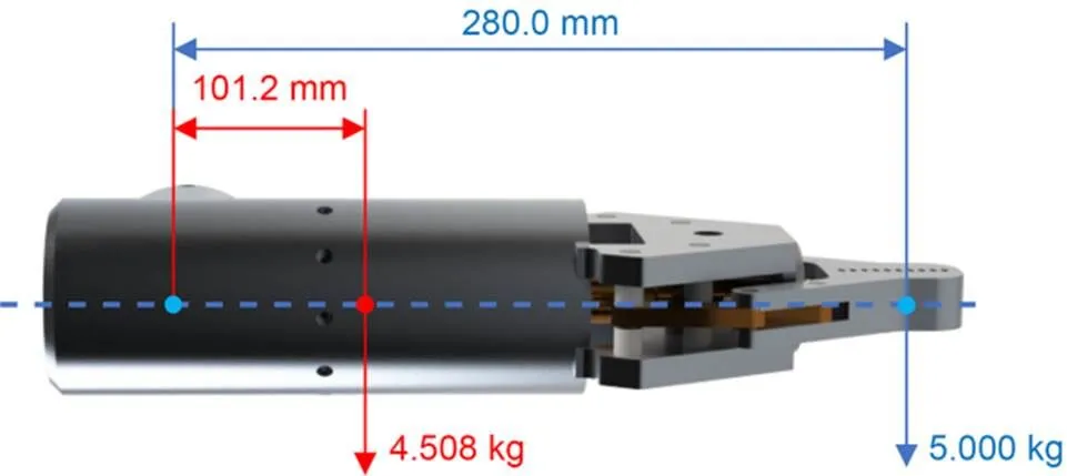
Fig. 2 Force analysis diagram of forearm joint

Fig. 3 Force analysis diagram of upper arm joint
According to the above requirements, motors with different performances have been selected for each joint. The parameters of each joint are shown in Table 2.
Unlike most hydraulic manipulators used underwater, the motor, a key component inside the manipulator, tends to fail when exposed to water, so electric manipulators have higher requirements for waterproofing and pressure resistance (Barbieri et al., 2018). Its complex shape makes a watertight design particularly important for the underwater manipulator. As depicted in Fig. 4, this study uses nitrile rubber type O-rings to seal the joint motor of the manipulator, where the two inner seals are used as a waterproof seal between the housing and the torque output block to play a static sealing role; the torque output block is used to connect the two joints and enable the motor to drive the joints to rotate; the outer seal is used to seal between the two adjacent joints, which can play a dynamic sealing role in this low-speed situation.
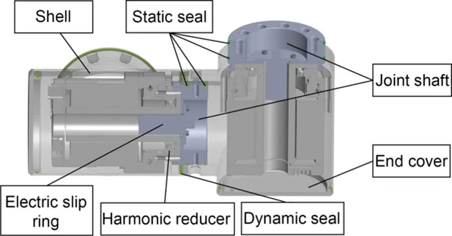
Fig. 4 Waterproof design of manipulator joints
To verify the sealing performance of the joint shell under high pressure, static finite element analysis of the manipulator shell was performed by simulating the external pressure environment at 100 and 700 m water depths, separately. As depicted in Figs. 5a and 5b, the displacement cloud diagram of the deformation of the outer surface of the simulated manipulator joint shell under pressures of 1 and 7 MPa is shown. From the analysis of the data in the figure, the maximum deformation of the shell is 0.069 and 0.486 mm under uniform pressures of 1 and 7 MPa, respectively. In a case, where the water depth does not exceed 100 m (1 MPa), it can meet the waterproof requirement. At a higher water depth, it is necessary to use the principle of pressure compensation to reduce the mechanical arm shell pressure resistance requirements. Therefore, the oil-filled cavity can be filled with oil compensation and equipped with a compensator to balance the internal and external liquid pressures.
2.2 Pressure-balancing device
According to the manipulator model, the internal oil-filling capacity of the manipulator is estimated to be 3 L. The volume change of the pure working fluid with a pressure change can be obtained from the liquid volume compression formula as:


Fig. 5 Simulation of pressure resistance of joint housing of manipulator
The maximum volume of compensation oil required due to pressure and temperature changes is 136.5 mL, and the working volume of the selected compensator needs to be greater than 136.5 mL. The volume of the compensator selected for the subject is 370 mL, as depicted in Fig. 6.

Fig. 6 Liquid pressure compensator
2.3 Docking method and mechanism design with AUV
To accommodate all the subsystems required to meet the project requirements, the AUV has been adapted to mount the robotic arm and gripper system at the bottom middle of the AUV, which meets the requirements of AUV suspension operations and minimizes the impact on the overall center of gravity of the UVMS system when the robotic arm is in motion. In previous UVMS-related studies, most of the robotic arms were mounted on the exterior of the vehicle (both bottom and front), which resulted in two consequences.
1. The complex configuration of the robotic arm led to high water resistance to the vehicle as a whole, making it very difficult for the vehicle to navigate at higher sailing speeds.
2. The water resistance brought by the mechanical arm affected the overall balance of the vehicle, forcing it to spend more energy on maintaining the overall balance of the thrusters, with impact on the system range.

Fig. 7 Schematic of AUV–manipulator system
In this study, when designing the connection mechanism, there should be a storage compartment for the manipulator inside the AUV, with a lifting mechanism to realize switching between the range and operation modes of the UVMS system. When the system is in operation mode, the lift mechanism pushes the manipulator out of the cabin to expand the operating range of the manipulator; when the system is in range mode, the manipulator is retracted into the storage cabin, and power is cut off to reduce the water resistance and the amount of power consumed by the robot arm, thus making the entire UVMS streamlined and improving its range. The vehicle with the manipulator integrated is depicted in Fig. 7.
Fig. 8 shows the manipulator lifting mechanism, consisting of an underwater electric push cylinder, a sliding rod, a connecting base plate, etc. The electric cylinder pushes the manipulator to move up or down. There are eight sliding rods to support the sliding and guiding roles of the manipulator. Each sliding rod is made of titanium alloy (TC4) to ensure that it can support the sliding and guiding of the manipulator.
The weight of the manipulator in air is 15.870 kg, and the center of mass and other geometric parameters of the manipulator are obtained by modeling software. In order to ensure that the analysis results can adapt to the force state of the manipulator in various states, it is assumed in the calculation that the end of the manipulator is holding an object weighing 5.000 kg. Under these conditions, an analysis of the force situation in the sliding rod section has been carried out, as shown in Fig. 9.
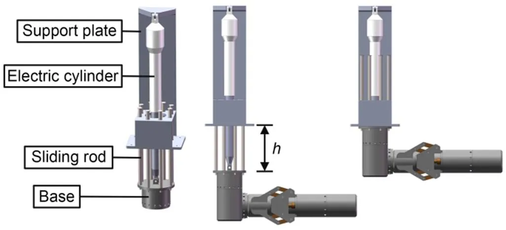
Fig. 8 Schematic of manipulator lifting mechanism. h is the sliding distance of the manipulator

Fig. 9 Schematic of force analysis
According to the principle of leverage, it can be determined that the maximum bending moment occurs when the manipulator is fully expanded and the base slides to the maximum stroke. The maximum bending moment () at the maximum sliding pivot point of the manipulator at rest can be calculated using the mass dimension parameters of the manipulator as:

In the ideal equivalent state, the bending moment is evenly distributed to the eight sliding rods of 12 mm diameter, the bending moment to each rod is 15.75 N·m, and if the total force is evenly distributed to each sliding rod, then the force to each rod is 25.586 N.

Fig. 10 Static finite element analysis of sliding rod

Fig. 11 Display of the working process of the lifting mechanism
Based on the above force analysis, the finite element simulation of the sliding rod is performed by taking Young's modulus=96 GPa, Poisson's ratio=0.3, yield strengthσ=800 MPa, and density=4600 kg/m3, combined with the mechanical property index of the TC4 material. Fig. 10 shows the simulation results.

3 Kinematic analysis
At least three parts of the system's kinematics have to be solved: a mathematical description of the kinematic chain, an algorithm for direct kinematics, and an algorithm for inverse kinematics.
The kinematic model of the underwater 5-function manipulator was determined using the Denavit-Hartenberg (DH) method. In particular, the 5-function manipulator configuration (Fig. 12) consists of a base, an end-effector, and five joints. The first three joints drive the rotation of the shoulder and elbow and the raising of the arm, respectively, whereas the last two joints are used to rotate the wrist for rotation and to open/close the fingers. The DH parameters are shown in Table 3, whereis the joint angle,is the linkage offset,is the length of linkage, andis the linkage angle.

Fig. 12 4-DOF configuration and DH convention

Table 3 DH parameters
The telescopic mechanism of this manipulator is independent of the DOF, and the manipulator has only four DOFs. Generally, a 3-DOF manipulator can satisfy the requirement that the end-effector reaches an arbitrary position in the workspace without regard to attitude.
Considering the limitation of the DOF of the manipulator, if the inverse kinematics of the manipulator is solved for any position and attitude, there is a high probability of no solution. The table of the manipulator control model is simplified by considering only the end positions of the first three joints controlling the manipulator, and the positive and negative kinematics are solved on the basis of the simplified DH table. The simplified DH parameters are shown in Table 4.

Table 4 Simplified DH parameters


wherecαdenotes cosα,sαdenotes sinα, andsandcdenote sinθand cosθ, respectively.
Eq. (6) can be substituted for the parameters in the DH table to calculate the homogeneous transformation matrix between the front and rear linkages of the actual manipulator.
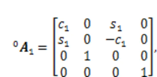
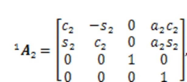


By substituting the joint variables into the positive kinematic equation of the manipulator, we can find the position of the end of the manipulator. We can also obtain all positions that can be reached by the end of the manipulator. We call this set of possible positions the reachable workspace, which is also an important parameter indicator for the manipulator. To ensure that the manipulator does not collide with the AUV during movement, we set the limit ranges of the joint angles as shown in Table 5. Using the Monte Carlo random number method, the resulting point cloud of the manipulator workspace is illustrated in Fig. 13.

Table 5 Angle range of each joint of the manipulator
From Fig. 14, we can intuitively understand the working space of the manipulator in the UVMS system, and through aggregate calculations, we can ensure that the illumination range of the light source covers the working space of the manipulator.

Fig. 14 Schematic of UVMS system workspace
In the design of automatic control algorithms for manipulators (intelligent path-planning algorithms), we frequently need to invert the angle of each joint of the manipulator based on the end position pose we desire (Sekkat et al., 2021). There are various methods for solving the inverse kinematics of a manipulator, such as geometric and analytical methods. In this study, the analytical method is used to solve the inverse kinematic equations of the manipulator (Youakim et al., 2020).

where,, anddescribe the spatial orientation of the end effector, whilerepresents the position coordinates of the gripper. By solving the simultaneous Eqs. (10) and (11), we can obtain the following formula:
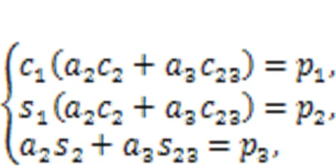
where23indicates cos(2+3), and23indicates sin(2+3).


The sum of the squares of both sides of the three equations in the equation system shown in Eq. (12) is found as:


If the coordinates of the target point exceed this range, it will exceed the reachable workspace of the manipulator. Therefore,

It follows from Eq. (14) that

The two solutions of3can be obtained from Eq. (19) as:


It follows from Eq. (12) that


Since3has been found, it can be solved:
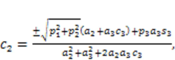

The same reasoning as in Eq. (19) yields:

According to the sign of3in Eq. (18), the four solutions of2can be solved as follows.


Rewriting the first two equations in Eq. (12) yields:


The two solutions of1are solved as follows:


Simplification gives:

From the above solutions of1,2, and3, the following four sets of solutions exist after permutation and combination, which correspond to the four poses of the manipulator reaching the same target position.


4 Experiment
The main part of the experiment was conducted on the actual manipulator. The main control system of the manipulator was the robot operating system using a Nvidia Jetson Xavier NX processor, and the node communication mode of topic communication was used to realize the design of the proportion integration differentiation (PID) control program of the manipulator (Simetti et al., 2014). The proportion, integration, and differentiation parameters are tuned individually to optimize the kinematic solution of the manipulator (Fernando and Perera, 2022). To observe the response speed and dynamic tracking error of the manipulator more intuitively, the point-to-point (PTP) joint angle trajectory is set here, and the manipulator is operated in air and water PTP cyclic trajectory tracking experiments separately. The contents of the two experiments are described, and the experimental data are analyzed.
As shown in Fig. 15, the same rotation angle trajectory curve is set for each joint, and the trajectory curve is quadratically interpolated at each cusp on the basis of trapezoidal waves, making the trajectory curve quadratically derivable; the angular acceleration at the position, where the angular velocity is changed, is uniform acceleration or deceleration. In such a cyclic test trajectory, we can observe at one time the performance of the manipulator in various states such as acceleration, deceleration, constant speed, and standstill. The initial position of the manipulator is set to the horizontally extended state, as depicted in Fig. 16a.
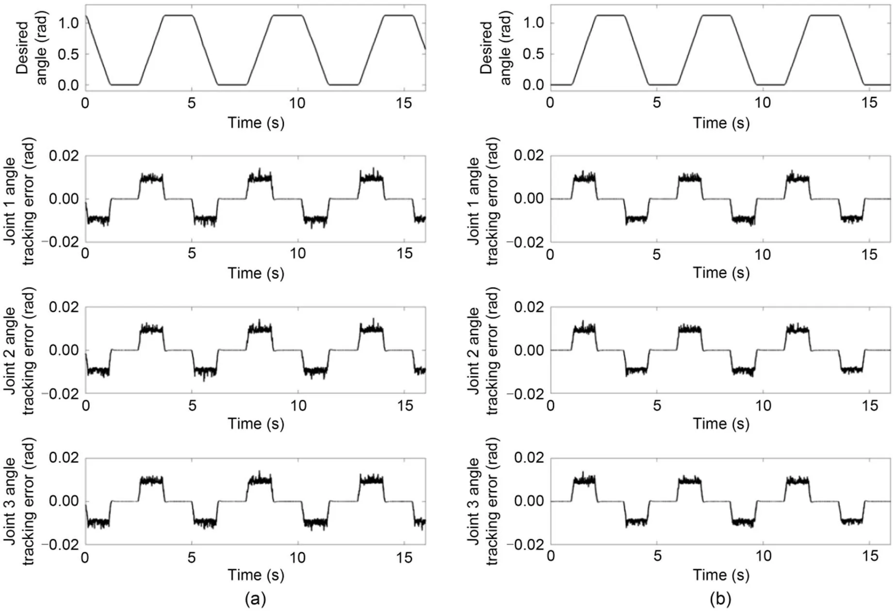
Fig. 15 Angle tracking error of each joint in air (a) and water (b)

Fig. 16 Underwater experiment of manipulator: the initial (a), middle (b), and end (c) poses of the trajectory running for one cycle
The experimental data of the above-water and underwater experiments are compared. Fig. 15 shows the dynamic joint angle tracking error graphs of each joint of the above-water or underwater manipulator. By comparison, it can be concluded that the manipulator joints operate more stably in the uniform acceleration/deceleration process, with a trace overshoot at the transition from uniform deceleration to a stop. In the uniform speed process, the joint angle tracking is unstable, and the error range is approximately 0.01 rad, as shown by the fluctuation amplitude. Fig. 17 further analyzes the motion trajectory error of the manipulator actuator. By comparison, it can be concluded that the average peak of the absolute tracking error of the manipulator in air is approximately 18 mm, whereas that underwater is approximately 14 mm. The end motion accuracy of the manipulator in water is higher than that in air, and the amplitude of the vibration generated during the uniform speed is also smaller than that during air operation.

Fig. 17 Space motion trajectory error of the end-effector of a manipulator in air (a) and water (b)
5 Conclusions
This study presents a new set of solutions for the field of underwater manipulation. A lightweight underwater electric manipulator that can be mounted on an AUV is designed and fabricated. The switch of the manipulator's working mode on the UVMS platform is achieved by designing a lifting structure assembly. The underwater manipulator is equipped with a separate end-effector, aiming to maximize the universality of the actuator and to make it easier to design new actuators for different usage scenarios. In addition, the kinematic analysis and workspace calculation of the manipulator system were performed, and PTP trajectory tracking experiments were conducted in air and water, which obtained significant amounts of experimental data.
However, this solution imposes many limitations on the performance of the overall system and requires a specific software solution. The fact that the proposed innovative solution requires a first feasibility study aimed at identifying the strengths and weaknesses of its design and control system, followed by further improvements, justifies this design approach. The analysis shows that to improve the performance of the robotic arm system, a more accurate control system needs to be designed, along with hydrodynamic analysis (Simetti and Casalino, 2016), and an AUV with a vision system is required to conduct further autonomous operation experiments (Simetti et al., 2018) in the underwater environment as well as in the actual marine environment (Tarn et al., 1996).
This work is supported by the Key Research and Development Program of Zhejiang Province (No. 2021C03013), China.
Xiaohui HU designed the research. Ziqiang REN and Hang ZHOU processed the corresponding data. Xiaohui HU wrote the first draft of the manuscript. Ziqiang REN helped to organize the manuscript. Jiawang CHEN revised and edited the final version.
Xiaohui HU, Jiawang CHEN, Hang ZHOU, and Ziqiang REN declare that they have no conflict of interest.
Barbieri L, Bruno F, Gallo A, et al., 2018. Design, prototyping and testing of a modular small-sized underwater robotic arm controlled through a master-slave approach., 158:253-262. https://doi.org/10.1016/j.oceaneng.2018.04.032
Evans J, Redmond P, Plakas C, et al., 2003. Autonomous docking for intervention-AUVs using sonar and video-based real-time 3D pose estimation. Oceans 2003. Celebrating the Past ... Teaming Toward the Future, p.2201-2210. https://doi.org/10.1109/OCEANS.2003.178243
Evans JC, Keller KM, Smith JS, et al., 2001. Docking techniques and evaluation trials of the SWIMMER AUV: an autonomous deployment AUV for work-class ROVs. MTS/IEEE Oceans 2001. An Ocean Odyssey. Conference Proceedings, p.520-528. https://doi.org/10.1109/OCEANS.2001.968776
Fernandez JJ, Prats M, Sanz PJ, et al., 2013. Grasping for the seabed: developing a new underwater robot arm for shallow-water intervention., 20(4):121-130. https://doi.org/10.1109/MRA.2013.2248307
Fernando S, Perera M, 2022. Development of an underwater robotic arm using multibody dynamics approach., 40:120-125. https://doi.org/10.21595/vp.2021.22301
Han J, Chung WK, 2008. Coordinated motion control of underwater vehicle-manipulator system with minimizing restoring moments. IEEE/RSJ International Conference on Intelligent Robots and Systems, p.3158-3163. https://doi.org/10.1109/IROS.2008.4650974
Leonessa A, 2008. Underwater robots: motion and force control of vehicle-manipulator systems (G. Antonelli; 2006) [book review]., 28(5):138-139. https://doi.org/10.1109/MCS.2008.927329
Marani G, Choi SK, Yuh J, 2009. Underwater autonomous manipulation for intervention missions AUVs., 36(1):15-23. https://doi.org/10.1016/j.oceaneng.2008.08.007
Paull L, Saeedi S, Seto M, et al., 2014. AUV navigation and localization: a review., 39(1):131-149. https://doi.org/10.1109/JOE.2013.2278891
Ridao P, Carreras M, Ribas D, et al., 2015. Intervention AUVs: the next challenge., 40:227-241. https://doi.org/10.1016/j.arcontrol.2015.09.015
Rigaud V, Coste-Maniere E, Aldon MJ, et al., 1998. UNION: underwater intelligent operation and navigation., 5(1):25-35. https://doi.org/10.1109/100.667323
Sekkat H, Tigani S, Saadane R, et al., 2021. Vision-based robotic arm control algorithm using deep reinforcement learning for autonomous objects grasping., 11(17):7917. https://doi.org/10.3390/app11177917
Simetti E, Casalino G, 2017. Manipulation and transportation with cooperative underwater vehicle manipulator systems., 42(4):782-799. https://doi.org/10.1109/JOE.2016.2618182
Simetti E, Casalino G, Torelli S, et al., 2014. Floating underwater manipulation: developed control methodology and experimental validation within the trident project., 31(3):364-385. https://doi.org/10.1002/rob.21497
Simetti E, Wanderlingh F, Torelli S, et al., 2018. Autonomous underwater intervention: experimental results of the maris project., 43(3):620-639. https://doi.org/10.1109/JOE.2017.2733878
Spenneberg D, Albiez J, Kirchner F, et al., 2007. C-manipulator: an autonomous dual manipulator project for underwater inspection and maintenance. Proceedings of the 26th International Conference on Offshore Mechanics and Arctic Engineering, p.437-443. https://doi.org/10.1115/OMAE2007-29202
Tarn TJ, Shoults GA, Yang SP, 1996. A dynamic model of an underwater vehicle with a robotic manipulator using Kane’s method., 3(2):269-283. https://doi.org/10.1007/BF00141159
Youakim D, Cieslak P, Dornbush A, et al., 2020. Multirepresentation, multiheuristic A* search-based motion planning for a free-floating underwater vehicle-manipulator system in unknown environment., 37(6):925-950. https://doi.org/10.1002/rob.21923
应用于作业式水下自主潜航器的水下电动机械手研发
胡晓辉1,2,陈家旺1,2,3,周航1,2,任自强1,2
1浙江大学,海洋学院,中国舟山,316000;2浙江大学海南研究院,中国三亚,572000;3教育部海洋传感技术与装备工程研究中心,中国舟山,316021
1. 以水下轻量化水下电动机械臂为研究对象,探索水下电动机械臂和自主水下航行器(AUV)的集成技术,设计一套全新的适用于500 m以上水深的水下机械臂。2. 提高AUV的现场操作干预能力和自主作业能力,为海底探测取样作业提供更加有效、经济、方便、快速的手段,在海洋资源探测中发挥更大的作用。
1. 以水下轻量化水下电动机械臂为研究对象,探索水下电动机械臂和AUV的集成技术,设计了一款全新的适应AUV搭载的水下电动机械手。2. 该水下电动机械手的密封方式借鉴了深海液压系统的工作原理,采用压力补偿的方式提升电动机械手本身的耐压性和防水性,提升了电动机械手的适用水深和水下工作的可靠性。
1. 基于机器人运动学与动力学理论,进行仿真验证,并搭建水下电动机械手实验平台。2. 进行陆上和水下的实验,完成轨迹的跟踪实验,并对水上水下和仿真实验的数据进行对比分析,得到水下电动机械手的轨迹跟踪精度,以验证该机械手的运行精度。
1. 在匀加速/减速过程中,机械手关节的运行更加稳定;在从匀减速到停止的过渡阶段有微量的过冲;在匀速运动过程中,关节角度跟踪不稳定,从波动幅度来看,误差范围约为0.01 rad。2. 通过进一步分析机械手致动器的运动轨迹误差可以得出,机械手在空气中的绝对跟踪误差峰值约为18 mm,而在水下约为14 mm;机械手在水下的末端运动精度比在水中高,匀速时产生的振动幅度也比在空气中小得多。3. 要提高机械臂系统的性能,需要设计更精确的控制系统;进行流体力学分析,还需要搭载配备视觉系统的AUV,以便在水下环境和实际海洋环境中进行下一步的自主操作实验。
水下电动操纵器;逆运动学;轨迹规划;轨迹跟踪精度
https://doi.org/10.1631/jzus.A2200621
https://doi.org/10.1631/jzus.A2200621
Jiawang CHEN, https://orcid.org/0000-0002-6351-0062
Received Dec. 28, 2022;
Revision accepted May 31, 2023;
Crosschecked Jan. 22, 2024
© Zhejiang University Press 2024
 Journal of Zhejiang University-Science A(Applied Physics & Engineering)2024年3期
- Journal of Zhejiang University-Science A(Applied Physics & Engineering)的其它文章
- A method for support stiffness failure identification in a steel spring floating slab track of urban railway: a case study in China
- Churning loss characteristics of a wet three-phase high-speed reluctance motor
- Synthesis and characterization of three new solid polyoxometalates based on Wells-Dawson-derived sandwich-type polyanions Co4(H2O)2(P2W15O56)2]16-
- Non-uniform thermal behavior of single-layer spherical reticulated shell structures considering time-variant environmental factors: analysis and design
- Recent progress in the development of dielectric elastomer materials and their multilayer actuators
