
基于OPNET的低轨卫星的点波束确定算法
2011-05-05 22:55于佳宗鹏
于 佳 宗 鹏
(南京航空航天大学航天学院,南京,210016,中国)
INTRODUCTION
Due to superior performances of low earth orbit(LEO)satellites,such as global coverage,low transmission loss,small end-to-end delay and user mobility,it has become a hot topic in the global personal wireless communication.In the terrestrial wireless communication,it can improve the system capacity by the way of frequency reuse[1],while in the satellite communication,it will implement the frequency reuse by the way of multiple spot beam.T he methods of multiple spot beam adopted for frequency reuse has been the concept of satellite cellular coverage.One coverage area of the spot beam is considered as one″cell″[2].
Currently there are two typical spot-beam models with equal beam width and equal spotarea.The antenna angle of equal beam width model(half-power beam width)is equal,while the geocentric angle of equal spot-area model is equal.T he antenna structure and parameters of equal beam width model are completely equal,as it is beneficial to the simplification of satellite antenna.T he equal spot-area model has two potential values:(1)The antenna angle of the spot beam which takes substellar point as the center is larger than others,in addition,the antenna gain is smaller.However,the antenna angle of view of the spot beams which are far away from the substellar point is smaller and the antenna gain is larger.It compensates the increase in path loss which is caused by larger propagation path in some extent.(2)T he equal spot-area model is beneficial to the even coverage of system capacity for terrestrial service area.For the mobile cells which move with the movement of constellation,the equal spot-area model is a better choice[2-5].
1 GEOMETRICAL RELATIONSHIP OF SATELLITE ORBIT
LEO satellite constellation can be classified into two groups based on the shape of orbits:elliptical or circular[6].When a circular orbit is in use,the earth is located at the orbit center.The inclination angle and the altitude of the satellite from the earth center are constant during the mo-tion.T he speed of the satellite is fixed during the rotation.Iridium constellation[7]is a classical example of circular orbits.Iridium satellites are distributed among six evenly spaced,near-polar orbits with 86.4°inclination and 780 km above the earth.Sixty-six satellites provide the overlapping global coverage,including polar regions[8-9].
Suppose that satellites are particles and the earth is a perfect ball,the orbits of the LEO satellites are conic(circular or elliptical)sections.Based on Kepler′s three laws of planetary motion and the orbital theory,the satellite orbit equations in orbital plane coordinate system can be obtained in Eq.1.In this paper,we need to know where the satellite is from an observation point on the earth surface,so a transformation from the orbit plane coordinates(x0,y0,z0)to the rectangular coordinates(xr,yr,zr)is given in Eq.(2)
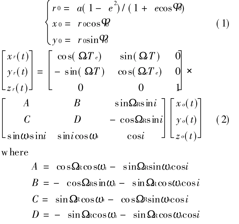
Here are some orbital elements:Inclination i,right ascension of the ascending node ΩR,eccentricity e,argument of perigee ωn,ΩeTe=ag0+0.250 684 47t is the universal time(UT),the standard time for most scientific and engineering purposes.r0is the radius of the orbit in polar coordinate, Φ0is measured from axis x0and is called the true anomaly.
2 SPOT BEAM MODELING
2.1 Judgement of central spot beam
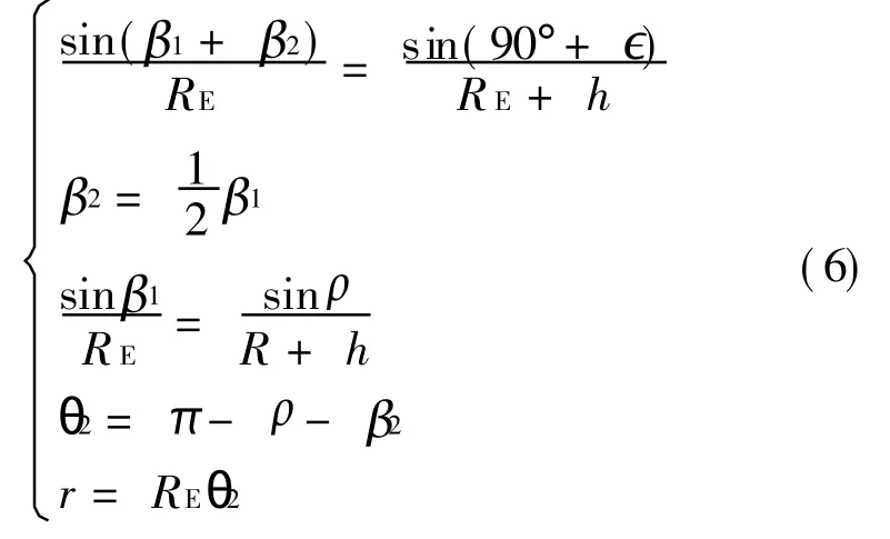
It shows the coverage of LEO satellite in Fig.1,RE=6 378 km is the radius of earth,h the height of the satellite,∈the minimal elevation,θ the included angle between the substellar point and edge point of the central spot beam.If it is the equal beam width model,β2is one half of β1,and if it is the equal spot-area model,θ2is one half of θ1.

Fig.1 Substellar point and spot beam
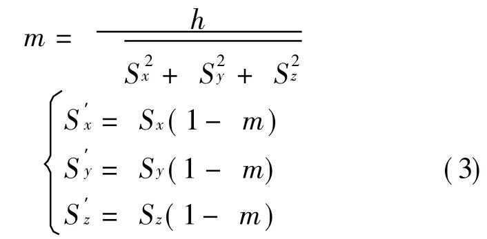
T he coordinate of the satellite is(Sx,Sy,Sz),the coordinate of the user is(Ux,Uy,Uz),the satellite,the substellar point,and the center of the earth whose coordinate is(0,0,0)are in the same straight.T he coordinate of substellar pointis obtained as
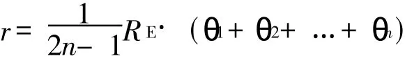
Then the radius of central spot beam r and the distance between the user and substellar point d can be calculated.According to r and d,the position relation of user and central spot beam is determinate.T he algorithm is as follows:
(1)Calculate the coordinates of the user and satellite.
(2)Calculate the coordinate of the substellar point.
If d>r,the user is not in the central spot beam,else the user is in the central spot beam.
T he distance between the user and substellar point is d=If it is the equal beam width model,the radius of central spot beam r can be obtained as

where s is the maximum distance between the satellite and the user.
If the spot beam has two layers,according to the sine theorem,it can be obtained as
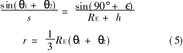
If the spot beam has three layers
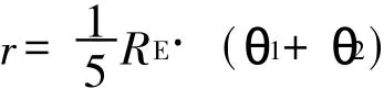
If the spot beam has n layers
If it is equal spot-area model,β2is one half of β1,the relationship among r,∈,β2and β1is given by(supposed the spot beam has two layers)
2.2 Judgement of outlying spot beam
The number of spot beams usually is one in the first layer(central spot beam),six in the second layer,twelve in the third layer,eighteen in the forth layer…and 6(n-1)-6 in the nth layer.
(1)Geometrical judgement of 2-D space
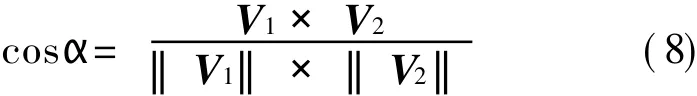
The sketch map ofsatellite coverage is shown in Fig.2.Supposing that O is substellar point,V1is the vector of the satellite′s motion direction,and V2is the vector which points from the substellar point to the user.

T he included angle between vector V1and vector V2is given by

Fig.2 Subastral beam coverage
T he angle range of αis(0°,180°).If the beam has two layers,according to Fig.2,it only can judge the user in spot beam 1 or spot beam 4,in spot beam 2 or 6,and in spot beam 3 or 5.The algorithm is given as

If the spot beam has three layers,as shown in Fig.3,the character c represents the third layer,the character a in the center represents the central spot beam,and the character d the forth layer.
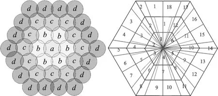
Fig.3 Four-layer beam
In Fig.4 it is obvious that A1B1=B1C1=C1A1,B1E1=E1D1=E1D1=F1C1,so it deduces that∠E1A1D1= ∠F1A1D1= 14.037 5°and∠B1A1E1=∠C1A1F1=15.962 5°.T he judgement algorithm of range of beam spot is presented as

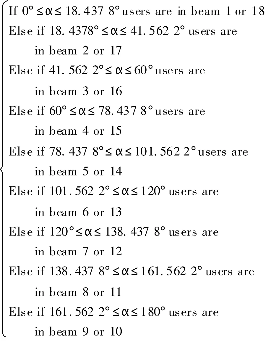
If the spot beam has four layers,the character d represents the forth layer.In Fig.4 it is obvious that A2B2=B2C2=C2A2andE2D2=D2F2=2B2E2= 2F2C2,so it deduces that∠E2A2D2=∠F2A2D2=18.437 8°and∠B2A2E2=∠C2A2F2=11.562 2°,the judgement algorithm of range of beam spot is given as
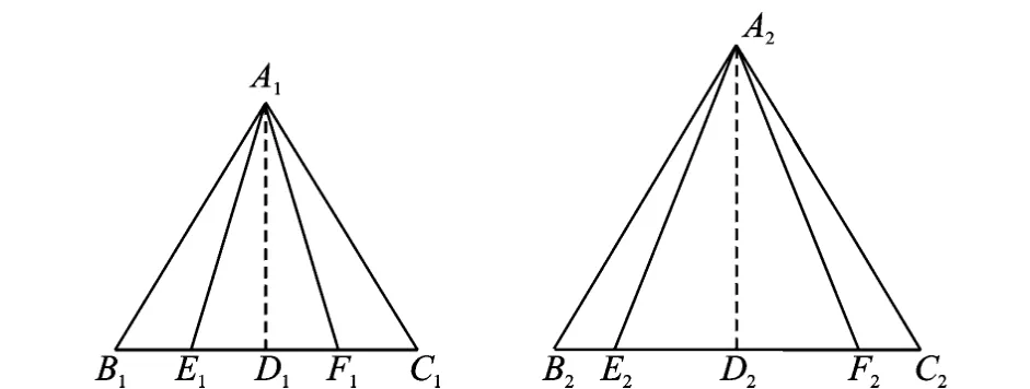
Fig.4 Relation graph of spot beam judgement
(2)Geometrical judgement of 3-D space
It cannot judge whether the user in the beam 2 or 6 in the 2-D space.In the 2-D space,the beam 2 or 6 represents that the user in the left or right of the satellite′s motion vector.In the 3-D space,the beam 2 or 6 represents that the user is above or below the orbital plane of satellite.
Supposing that the celestial sphere is divided into two parts by orbital plane of the satellite,it can determine whether the user is above or below the orbital plane with the method of left-hand rule.Flung up the left hand and crook the fingers,the direction of the thumb pointed represents that the user is above the orbital plane,while the opposite direction is below the orbital plane.
In Fig.5,B and A represent that the user is above or below the orbital plane respectively.Supposing that C is the reference point,O is the geo-centre.It is obvious that the angle of BOC is obtuse while the angle of A OC is acute.According to the angle it can deduce the position of user in space.Supposing that the longitude and latitude of user is(λu,),the longitude and latitude of reference point is(λu=Ωi+90°,∈-90°),therefore the included angle between the user and reference point is given as

T he algorithm is given as
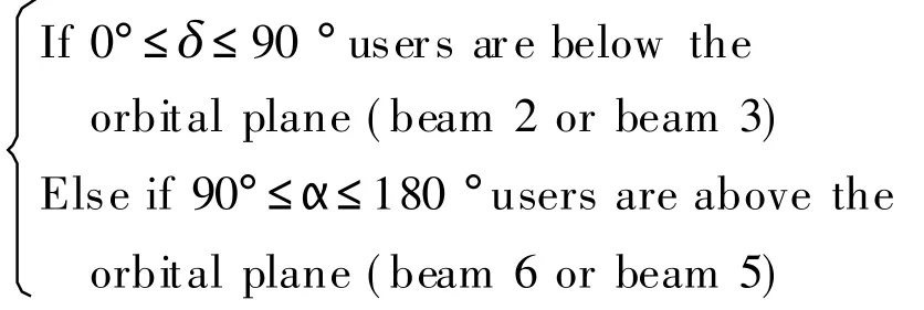
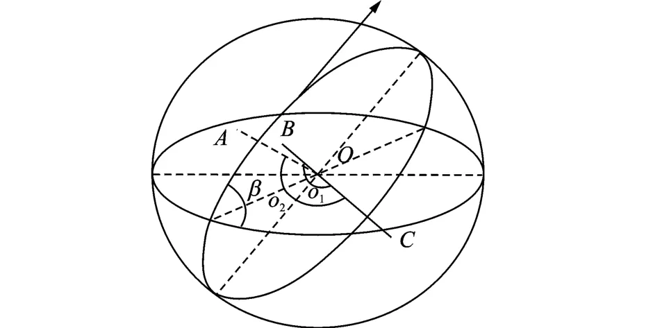
Fig.5 Spatial geometrical relationship between location of user,reference point and geo-centre
3 SIMULATION RESULT ANALYSIS
In this paper,an Iridium constellation system model is built based on OPNET platform combining with MAT LAB which is good at matrix operation.The world map is placed as the simulation background.Iridium orbital files are imported into OPNET model generated by ST K software with orbital parameters.T he nodes in the system are user terminals,Iridium satellite constellation and the earth stations.In the OPNET simulation,it should judge which spot beam the user is in and whether the user is above or below the orbital plane.T he flow chart is shown in Figs.6,7.
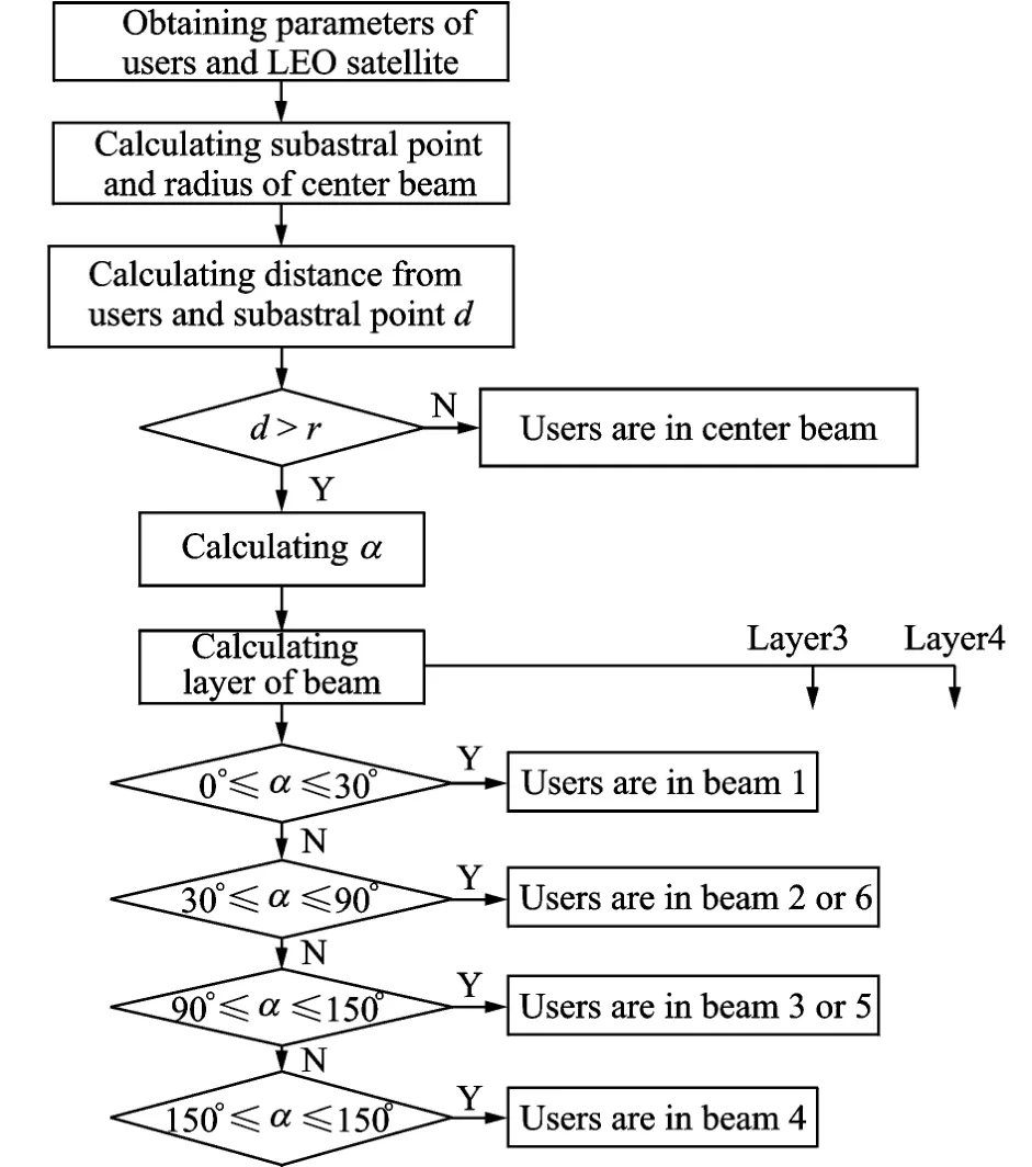
Fig.6 Spot beam judgement of 2-D space process in system
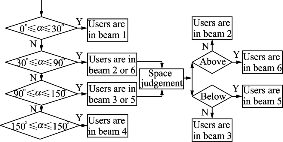
Fig.7 Spot beam judgement of 3-D space process in system
The simulation time is set as 48 h,and the users are located in the southeast whose latitude and longitude are about 31°N,121°E.T he orbital parameters of Iridium 8 are shown in T able1.

Table 1 Parameters of Iridium 8
T he selection of the next servicing satellite is based on some rules.In the paper,the minimum distance(MD)selection and the longest visible time selection are used.According to this criterion,the user will be served by the closest satellite or the longest serving satellite.For the user,no matter which satellite comes to access,the access criterions are the same.In the paper,the layers of beams are set as 2,3,4 and the beam shape is shown in Fig.3.
T he cumulative distribution of the satellite serving time is illustrated in Fig.8.We observe that 50% of the satellite serving time of the longest visible time selection is more than 350 s,while 50%of the satellite serving time of MD is only more than 200 s.T he average satellite serving time of the longest visible time selection is about 410 s,while the latter is 250 s.Therefore,there is a good agreement with the characteristics of Iridium constellation,and the hypothesis is accepted.The satellite serving time has obviously increased through the method of the longest visible time criterion.

Fig.8 Cumulative distribution of satellite serving time
In the following,the equal beam width model of 2,3 and 4 layers is adopted,respectively.In the same simulation condition,the average cell serving time curves of 2,3 and 4layers are shown in Figs.9,10,11,respectively.While the instantaneous cell serving time curves are shown in Figs.12,13 and 14.From Figs.9,10,11,it can be seen that the average cell serving time of 2,3 and 4 layer models is about 55,75 and 120 s.The instantaneous cell serving time vary from 0 s up to 600 s.
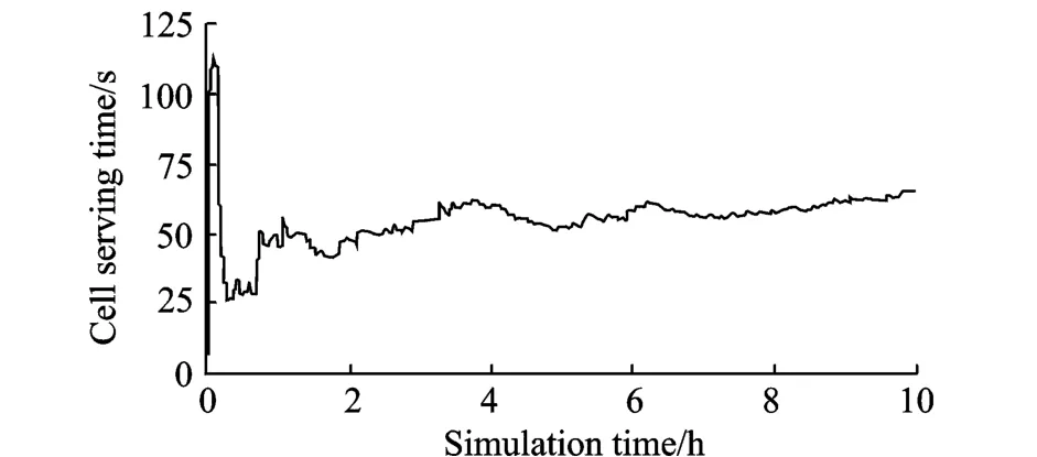
Fig.9 Average cell serving time curves of 2-layer beam

Fig.10 Average cell serving time curves of 3-layer beam

Fig.11 Average cell serving time curves of4-layer beam
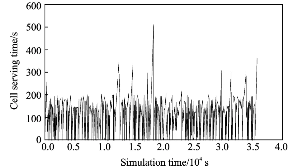
Fig.12 Instantaneous cell serving time of 2-layer beam
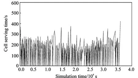
Fig.13 Instantaneous cell serving time of3-layer beam
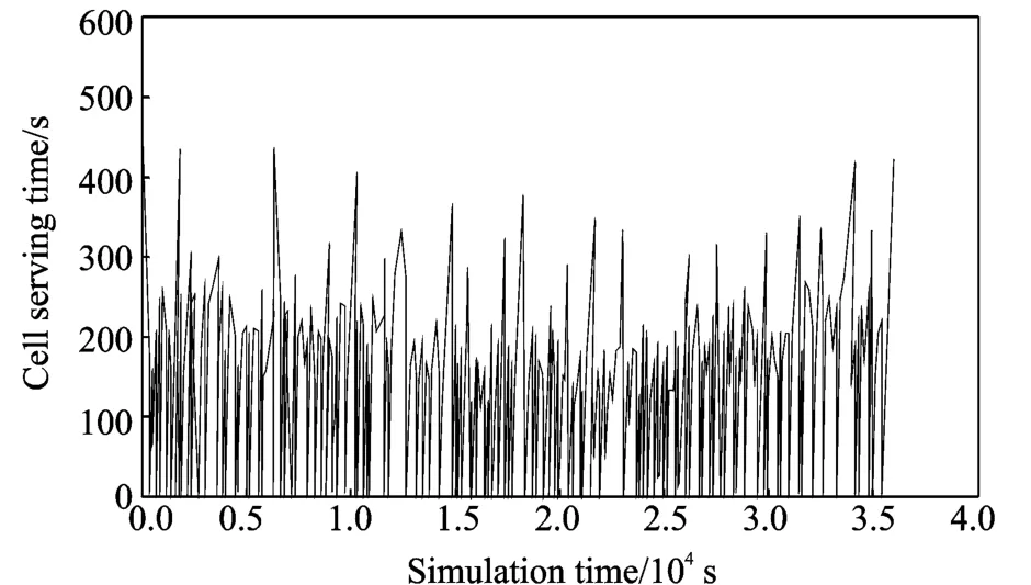
Fig.14 Instantaneous cell serving time of4-layer beam
4 CONCLUSION
In actual system,the handovers between different satellites or different beams vary with the pilot signal intensity.However,in the system simulation,it is impossible to determine the spot beam which the user is in through the method of pilot signal.Usually it will determine the spot beam which the user is in through the method of coverage in the simulation.In the paper,it presents a new spot beam judgement algorithm in LEO satellite constellation,and an Iridium model implemented on OPNET with dynamic topology nodes and network layer protocols is presented and simulation results are obtained.
[1] Ekici O A.Design issues and performance analysis of CDMA multi-beam satellites[J].Electrical and Computer Engineering,2004,2:1053-1057.
[2] Wei Hong.Multibeam antennas for next generation mobile communications and mobile satellite communications[C]∥2008 Loughborough Antennas&Propagation Conference.[S.l.]:IEEE,2008:58-61.
[3] Oliveri G L.Multibeam antenna arrays with common subarray layouts[J].IEEE Antennas and Wireless Propagation Letters,2010,9:1190-1193.
[4] Paraboni A,M auro B,Capsoni C,et al.Meteorology-driven optimum control of a multibeam antenna in satellite telecommunications[J].IEEE T ransactions on Antennas and Propagation,2009,57:508-519.
[5] Loreti P,Iuglio M,Palmombini I.Impact of multibeam antenna design on interference for LEO constellations[C]∥The 11th IEEE International Symposium on Personal,Indoor and M obile Radio Communications.London,U K:IEEE,2000:913-917.
[6] Yu Jia,Zong Peng.The analysis and simulation of communication network in iridium system based on OPNET[C]∥2010 2nd IEEE International Conference on Information Management and Engineering.Chengdu,China:IEEE Computer Society,2010:68-72.
[7] Yu Weijun,Qian Xianyi.Communication satellite orbit and iridium satellite plan′s restarting[C]∥2010 International Conference on Computer Application and System Modeling.Taiyuan,China:IEEE,2010:617-620.
[8] Ballard A H.Rosette constellations of earth satellites[J].IEEE T ransactions on Aerospace and Electronics Systems,1980,16(5):656-673.
[9] Collins L.Iridium satellite communication network[J].Engineering&Technology,2009,9:64-65.
猜你喜欢
中国机械工程(2022年21期)2022-11-21
环球时报(2022-08-16)2022-08-16
中国机械工程(2022年7期)2022-04-20
数据采集与处理(2021年4期)2021-09-20
成都信息工程大学学报(2021年6期)2021-02-12
舰船科学技术(2020年3期)2020-04-22
通信技术(2019年3期)2019-05-31
金色年华(2017年8期)2017-06-21
中国化肥信息(2016年41期)2016-05-17
连环画报(2015年8期)2015-12-04
 Transactions of Nanjing University of Aeronautics and Astronautics2011年3期
- Transactions of Nanjing University of Aeronautics and Astronautics的其它文章
- 冷却润滑介质对钛合金Ti6Al4V加工性能的影响
- 温度变化下基于兰姆波的复合材料结构损伤识别
- 基于因果图的微小型涡喷发动机安全性分析
- 基于遗传EM 算法的航班延误状态空间模型
- 基于GIS的机场净空障碍物评定研究
- 基于多GPU的大型线性和非线性方程组的求解