
Rigid-supported Submerged Floating Tunnel
2011-08-01 02:50GAORongjiang
隧道建设(中英文) 2011年5期
GAO Rongjiang
(Huhhot Railway Bureau,Huhhot 010050,China)
0 Introduction
The submerged floating tunnel has such advantages as short route,being little affected by seabed structure,highly optional site selection,being suitable for building in deep waters,etc.However,the anchorage system of ordinary submerged floating tunnel is of complex structure,difficult for anchorage and unsuitable for maintenance,so the cost is much higher than that of bridges or ordinary tunnels[1]139,which make this sea-crossing transport mode cannot be applied so far.Therefore,the scheme of submerged floating tunnel characterized by low price and availability has become the hot research spot for many countries.The Netherlands,Norway,US,and Japan are carrying out continuous research and improvement[1]139,but by now,there is no relevant breakthrough report.The rigid-supported submerged floating tunnel overcomes all disadvantages of ordinary submerged floating tunnel,and makes this ideal sea-crossing transport mode likely be widely applied.
1 General Structure of Rigid-Supported Sub merged Floating Tunnel
As shown in Fig.1,in general,it is composed of three parts,i.e.the tunnel tube,uplift steel piles,and auxiliary works at the tunnel entrance/exit.
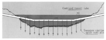
Fig.1 Sketch of rigid-supported submerged floating tunnel
1.1 Section structure of tunnel tube
The section structure of tunnel tube is shown in Fig.2.The inside is divided into three layers and 10 lanes.The tunnel tube has an outer diameter of 25m,inner diameter of 21.4 m,outer wall thickness of 100 mm,and inner wall thickness of 10 mm.The inside is stiffened(joist)both longitudinally and transversely.One 25 mm-thick and 1.7m-wide annular spacer plate(transverse hoist)is welded every 3 m in transverse direction.As shown in Fig.2,various round holes are made on the spacer plate for high-strength prestressed reinforcement.Between two annular spacer plates,one 25 mm-thick 1.7 m ×2.975 m longitudinal spacer plate(longitudinal hoist)is welded every 1m.High-strength concrete is compressively cast in the blanks between spacer plates.The total thickness of tunnel wall is 1.8 m.With a total area of cross section of 0.5 m2and a tensile strength of 1 960 MPa,the highstrength prestressed reinforcements are longitudinally tensioned in the middle of each section of tunnel tube,and the effective length is one half of the length of a single tunnel tube section.As the largest tunnel tube deformation is at the mid-span,prestressed reinforcements are used to enable vehicles to run smoothly.All the tunnel tubes are made of 15MnVq bridge structural steel and the tensile strength is 580 MPa[2-3].The prestressed reinforcements are not included in mechanical calculation,and in the design,if prestressed reinforcements are considered time-consuming,energy-consuming and uneconomical,the prestressed reinforcement structure may not be used.
The tunnel section is 300 m long,and its maximum designed live load is 15 000 t.Male counter flanges are welded at both ends,and they will be connected together with anti-rust bolts after the sealing ring is mounted.At the lowest place inside the tunnel tube,one high-pressure large-displacement submersible pump is set every 50~100 m with the discharge pressure higher than 0.8 MPa and the water outlet connected to the sea via a check valve for construction water discharge and leakage water discharge.All tunnel tubes will be subject to anti-rust treatment and leave the factory for shipment after both ends are blocked.
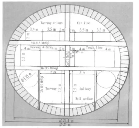
Fig.2 10-lane high-speed tunnel
1.2 Structure design and stress principle
1.2.1 Structure design
The tunnel inside is of the structure of multiple statically indeterminate beam.The stress distribution is even;the overall structural strength is large,the interior structural layout is logical,and the space utilization ratio is high.The tunnel is a continuous beam system in longitudinal direction.The structure with light width,large rigidity,and high bearing capacity is suitable for running of vehicles at a high speed.
1.2.2 Stress principle
The rigid-supported submerged tunnel is a rigid body and can bear stress in two ways[4].In the design,the tunnel tube and uplift piles should bear the negative bending moment and tensile stress resulting from buoyancy force that is one half of the maximum designed live load under the condition of on live load.At the maximum live load,one half of the positive bending moment and tensile stress(positive pressure)applied to the tunnel tube and uplift steel piles will be left minus the part counteracting the negative bending moment and tensile stress under thecondition of no live load.From no live load to the maximum designed live load,the maximum stress borne by the tunnel tube and uplift piles is one half of the maximum designed live load.Therefore,it can meet the stress demand of the maximum designed live load by just using one half of the steel stress section.The two-way stress design allows a reduction of steel consumption by 50%.Certainly,if there is no backing from the reliable uplift steel piles,such a design will be absolutely venturesome.
1.3 Feasibility of the scheme
1.3.1 Manufacturing capacity
China’s shipbuilding capacity has already reached the level of 300 000t.Compared with a ship,the tonnage and overall size of a tunnel tube is larger and the structure is far more complex.Therefore,based on the current technical level,China can readily manufacture the tunnel tube with a length of 300 m and diameter of 25 m.
1.3.2 Construction capacity
The 2 000 kN·m underwater hydraulic pile hammer available in the world can drive an end-open pile with a diameter of 3m into the hard soil,reaching a bearing capacity of 100 ~150MN[1]177.The main work quantity of rigid-supported submerged floating tunnel is centralized in underwater piling.Steel piles used for it have a diameter of 3 m,and the pile hammer available is suitable for this work.
1.3.3 Prior diving technology
A professional diver with a 12 L oxygen cylinder is capable of 1 h continuous underwater work at-150 m.The underwater working face of the rigid-support submerged floating tunnel is at the-65 m waters where diving operation is applicable.
According to the above analysis,the scheme of rigid-supported submerged floating tunnel is completely feasibly in terms of technology.
1.4 Advantages
1)The ordinary submerged floating tunnel is under one-way stress,and the stress is higher than the maximum designed live load while the rigid-supported submerged floating tunnel is under two-way stress and the stress is only equal to one half of the maximum designed live load,so more than one half of the steel consumption can be cut down.
2)The ordinary submerged floating tunnel is of the separate 3-tube and 6-lane design while the rigid-supported submerged floating tunnel is of the single-tube and 10-lane combined design,so the latter has the advantages of compact structure and high space utilization ratio which can achieve the traffic volume of 10 combined railway and highway lanes with the steel quantity equal to one half of that used for the three tubes and 6 lanes.Moreover,its span and collision resistance is much higher than the ordinary three-tube scheme.
3)Transverse ejection uplift steel piles are used as fixed support for the rigid-support submerged floating tunnel,which can significantly simplify the whole anchorage system,reduce the underwater work quantity,shorten the construction period,cut down the cost,and moreover achieve quick construction and reliable quality.
4)The rigid-supported submerged floating tunnel has a logical overall structure,large rigidity,strong overloading capability,and so is favorable for vehicles running smoothly at a high speed.The ordinary submerged floating tunnel doesn’t have these advantages.
2 Key Points of Construction
In order to make the tunnel tube and uplift steel piles successfully butt jointed underwater,the construction accuracy of longitudinal and transverse spacing of each pile must be lower than or equal to ±10 mm,and the vertical bisector of the line between centers of two transverse piles must coincide-with the longitudinal axis of the tunnel tube.To this end,a movable dual-tube support special for driving must be provided to ensure that the spacing is accurate,there is no rotation or displacement,and they can be used for many times while two transverse piles are driven into the seabed.
2.1 Construction of uplift piles
The rigid-supported submerged floating tunnel is directly fixed on the seabed via uplift steel piles.The distance between the tunnel top and sea surface is 40m.Uplift steel piles must have very reliable uplift-resisting and compression-resisting performance,and otherwise,it is impossible for the rigid-support submerged floating tunnel to bear two-way stress.The uplift steel piles have a diameter of 3 m,and the longest piles are 120 m long,their wall is 100 mm thick.They can also be made of 15 MnVq bridge structural steel,and all of them should be subject to anti-rust treatment before delivery.Each connection points of the tunnel tube should be fixed with one set of uplift piles(each set is made up of 4 piles),and connected into a triangular frame structure with channel steel underwater.Uplift steel piles have two structural types,and they should be driven into the seabed by dif-ferent method accordingly.In order to keep uplift steel piles have roughly equal uplift-resistance,all uplift steel piles should be driven into the seabed at a roughly same depth.
2.1.1 Uplift piles of manual excavation
Where an aquifuge is right below the pile,the openend steel piles welded with counter flange may be directly driven into the seabed at the required depth,and the counter flanges and the auxiliary steel sleeves with an equal inner diameter of the open-end steel piles should be butt jointed under a sealing condition to the open-end steel piles that have already been driven into the seabed.The other end of the auxiliary steel sleeves should be adequately above the water so that seawater cannot be filled in under the condition of maximum tidal level plus maximum wind and wave.Discharge all the seawater in steel piles,and dig up the earth in steel piles with a grab bucket to make the pile ends exposed.Build the uplift pile foundation manually before filling steel piles with high-strength concrete.Remove the steel sleeves after the concrete is set.This method requires more labor hour and is somewhat hazardous,but the quality is reliable.
2.1.2 Transverse ejection uplift piles
Where a pervious layer is right below the pile position and the aforementioned construction method is inapplicable,weld a conical pile toe onto the lower end of the open-end steel pile to change it into closed-end pointed pile.Mount four multiple-step two-way jacks with a maximum extension diameter of 1 m in transverse direction at the lower part of the pile in 4 layers at equal angle(as shown in Fig.3).If it’s difficult to drive the pointed pile into the seabed,make a proper hole at the center of the pile position to guide it in.After reaching the required depth,start the hydraulic pump to make all extendable parts of the multiple-step two-way jack extend in place and directly insert into the formation of the pile foundation and finally cast concrete into the pile.The effective area of the extending part is about 2.6 times more than that of the steel pile bottom area,and if the uplift resistance of the steel pile is still inadequate,use additional jacks or increase structural size of the steel pile and jack.
The step-1 piston of the multiple-step two-way jack can reciprocate and grouting holes are made around the extending part of the piston.After all pistons extend in place,drawback the step-1 piston,and grout the cavity left by the piston.After the cavity is full,make all pistons extend in place for the second time to squeeze the concrete grout to everywhere.The set concrete can significantly improve bearing capacity of uplift piles.If the formation is soft and loose,grout repeatedly till the requirement can be satisfied.
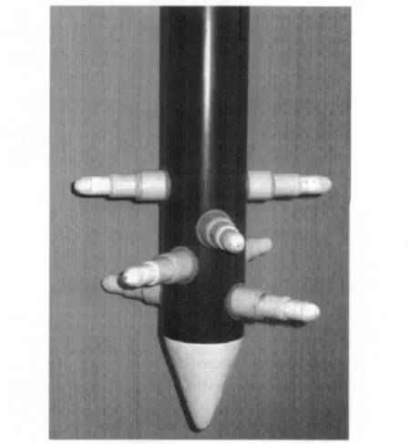
Fig.3 3-level bi-directional jack at bottom of lateral-jacked antiuplift steel pile
The transverse ejection uplift pile is a kind of novel structure that was never used before.It is characterized by high uplift resistance and compression resistance,easy and quick construction,reliable performance,no earthworks,and no pollution.If it is used as the foundation piles of high and large buildings,the safety and quakeproof performance of buildings will be better.If it is used as the tower foundation piles of cable stayed bridges and suspension bridges,settlement of the tower will be lower and the number of foundation piles will be smaller.If it is used as anti-uplift and anti-slide components of anchorage of suspension bridges,the volume and cost of the anchorage will be significantly reduced.Therefore it is a novel structure of great popularization and application value.
The structure and working condition of the multiplestep two-way jack is shown in Fig.4.
Where an aquifuge is right below the pile position,the transverse ejection uplift piles may be used,and in this way,construction will be significantly accelerated.

Fig.4 Structure of 3-level bi-directional jack
2.2 Connection of tunnel tube and uplift steel piles
As shown in Fig.5,connection of the tunnel tube and uplift steel piles has two structural types.If the accuracy of the longitudinal and transverse spacing between uplift steel piles driven into the seabed is within ±10 mm,the structural type shown in Fig.5(a)can be used,and in this way,4 000t steel can be saved.If the longitudinal accuracy cannot meet this standard,the structural type shown in Fig.5(b)can be used.Although the structural type shown in Fig.5(b)sets forth no requirement for longitudinal accuracy,more steel will be used.
2.3 Underwater butt jointing and fixing of tunnel tube
After all the uplift steel piles are fixed in place,lift and place the lower pieces of the tunnel tube clips onto flanges of uplift steel piles in order(be sure the locating pin of two piles is put into the hole),and convey the tunnel tube to the specified location by buoyant towing.Fill water in the tunnel tube with assistance of lift-off ship to keep the tunnel tube in a floating state,and then carry out underwater butt jointing section by section from one bank to the other.After butt jointing of one section is finished,fix it with tunnel tube clips and then discharge the water in the tunnel tube.Thoroughly seal the joint by electrical welding inside the tube to prevent leakage caused by failure of sealing rings after years.Remove the blocking plates between tunnel tubes for future reuse.After butt jointing is all finished,commence on all follow-up work inside the tunnel,such as lighting installation,paving,railway laying as well as installation of all facilities of communication,ventilation,fire protection,internal monitoring,etc.
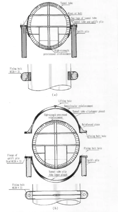
Fig.5 Connection between tunnel tube and anti-uplift piles
3 Safety Measures of the Tunnel
1)The tunnel site should be far away from the intersection of the main navigation channel and crossover,because in this way the probability of tunnel damage caused by ship wreck can be significantly reduced.As there are a few underwater submarines with small tonnage and all of them are equipment with advanced navigation devices,the probability of submarines colliding with the tunnel is very slim.Moreover,the total wall thickness of the tunnel tube is 1.8 m,and its outer steel wall thickness is100 mm,so it can resist a certain impact,and be safe in case of general collision.Therefore,it is not required to consider the danger of collision by submarines.For any eventuality,it can be specified that the submarine must float above the sea when crossing the tunnel.
As the tunnel is of steel structure with high toughness,a general earthquake will not damage it.
2)In case of a collision and damage accident,start the drainage facilities immediately for emergency drainage to allow all vehicles and personnel inside the tunnel to escape in adequate time.
3)Every 20m in the tunnel,set a fire hydrant and a hand-propelled fire engine filled with fire extinguishing agent for electrical appliance fuel oil ready for vehicle fire.Full-time firemen should be appointed to escort in transport when an oil truck passes through the tunnel.
4)Set emergency exits in certain quantity on the middle partition wall of each layer of the tunnel for maintenance personnel or emergency cases.
4 Ventilation Facilities of the Tunnel
1)Set exhaust inspection stations at the tunnel entrance/exit to prevent vehicles not meeting the emission standard entering the tunnel.
2)Set jet ventilators in sections of the special ventilation duct of the tunnel to force fresh air into the tunnel.Vent the contaminated air in the tunnel with the jet ventilators mounted on the top of the uppermost layer of the tunnel via ventilation holes on roof plate of each lane.
3)Ventilation cars should be used for ventilation.Prepare ventilation cars at the tunnel entrance/exit.The ventilation cars can run a speed higher than 100 km/h,and can be used at any time according to the quality requirement for air in the tunnel.
①Structural principle,operation method and expected effect of ventilation cars.Install parawing-shaped folding ventilation piston plates in two layers(one front layer and one rear layer)on chassis of high-power motor cars or electric cars.When the ventilation cars run at a high speed,a strong piston effect will be generated to force the air in the tunnel to flow and renew.Two or more ventilation cars can be used at the same time when necessary.According to estimation,ventilation cars will bring about better effect than the jet ventilation,and moreover cost and operation cost will be lower than that of jet ventilators.
②The reasons why the rigid-support submerged floating tunnel at Qiongzhou strait provided with no ventilation tower/shaft:as the rigid-support submerged floating tunnel is for combined highway and railway use,the maximum slope will not be more than 10‰;for motor cars it is equal to a flat road and moreover,lanes in the tunnel are wider than standard ones and cars run in one way in the tunnel,so it is estimated that the normal running speed of cars in the tunnel will be higher than 80 km/h,and the ventilation effect generated by the piston effect of cars themselves may make the air in the tunnel meet the required quality.Even if the quality requirement cannot be satisfied,in addition to aforementioned two ventilation modes,ventilation in the tunnel will not be problematic.Therefore,the author claims that the special ventilation tower/shaft may not be provided for the rigidsupport submerged floating tunnel at Qiongzhou strait,and in this way a huge amount of investment can be saved and the risk of ship collision can be mitigated.Nevertheless,if there is no choice but to build special ventilation tower/shaft,it is just a matter of cost increase[5].
5 Economic Analysis
5.1 Cost
The cost of the scheme of single-tube 10-lane rigidsupport submerged tunnel was calculated based on the 19.5 km long New Line V of Qiongzhou Strait.Roughly 3 500 000t steel and more than 2 500 000m3concrete was used,and the total cost is about RMB 70~80 billion according to the monetary value in 2011,which is the lowest among all sea-crossing schemes.
5.2 Benefit Maximization by technological innovation
As the design philosophy of two-way stress and combined structure is applied to the rigid-support submerged floating tunnel,and transverse ejection uplift steel piles are used as the fixed supports of tunnel tube,the cost of one-lane works is less than one half of that of a bridge or ordinary tunnel.Thanks to the reduced processes and underwater work quantity,the construction period is about 2~4 years,which is significantly shortened by about 4 years compared with the construction period of bridges and ordinary tunnels.The works completed and put into operation ahead of schedule can bring about immeasurable social benefit and economic impetus.
6 Conclusion and Discussion
1)Conclusion:It is feasible,economical and ideal for the scheme of single-tube 10-lane rigid-support submerged tunnel to be adopted as the scheme of permanentand calculation should be carried out to validate whether the strength,rigidity,stability,shapes,sizes and materials described in the present paper are logical or not;③The way to safely implement the construction scheme should be further detailed;④ Of course,testing research may be carried out at first.
[1] 唐寰澄.世界著名海峡交通工程[M].北京:中国铁道出版社,2004:139,177.(TANG Huancheng.World-famous strait transport works[M].Beijing:China Railway Publishing House,2004:139,177.(in Chinese))
[2] 邵旭东.桥梁工程[M].武汉:武汉理工大学出版社,2003.(SHAO Xudong .Bridge works[M].Wuhan:Wuhan University of Technology Press,2003.(in Chinese))
[3] 盛洪飞.桥梁墩台与基础工程[M].哈尔滨:哈尔滨工业大学出版社,2005.(SHENG Hongfei.Bridge pier,abutment and foundation works[M].Harbin:Harbin Institute of Technology Press,2005.(in Chinese))
[4] 单辉祖.材料力学教程[M].北京:国防工业出版社,1983.(SHAN Huizu.Course of material mechanics[M].Beijing:National Defense Industry Press,1983.(in Chinese))
[5] 铁道部.中华人民共和国铁路技术管理规程[S].北京:中国铁道出版社,2000.(Ministry of Railways.Railway technology management regulation of the Peoples Republic of China[S].Beijing:ChinaRailwayPublishingHouse,2000.(in Chinese))sea-crossing channel under the specific geological structure conditions of Qiongzhou strait.
2)Practical value and significance of the present research theory:The scheme of rigid-support submerged tunnel not only is of great reference value for permanent sea-crossing channel works at Qiongzhou strait but also for permanent sea-crossing channel works under similar conditions in other places worldwide.
3)Existing problems difficult to solve:The scheme of rigid-support submerged tunnel doesn’t thoroughly solve the ventilation of long and large tunnels.For tunnels with a length more than 50km,ventilation is a problem pressing for solution.The main problem is air intake.The longer the air duct route is,the lower the ventilation efficiency will be.How to shorten the route of the ventilation system to improve the ventilation efficiency is an important topic for future research.
4)In the present paper,a tentative idea about building rigid-support submerged floating tunnel under the sea is set forth,but there are many problems about the rigid-support submerged floating tunnel which need further intensive research,for instance,①Further investigation and calculation should be carried out to determine what ventilation scheme is more scientific and logical through demonstration by data;②Further detailed design说明:该文的中文原文已在《隧道建设》2009年第5期发表,作者此次对原文做了一些修改,说明如下。
1)关键词
“三级双向千斤顶”改为“多级双向千斤顶”,是为适应实际需要。
2)1.1
隧道管断面结构由“4层14车道”改为“3层10车道”,主要为了增加每层隧道的净高,提高隧道的通过能力,也为了减轻驾驶员的压抑感。
隧道管在中部张拉预拉筋是为了减小隧道管的弯曲变形,但布设难度很大,费时费力,又因隧道管为便于拉运,节长由“500 m”改为“300 m”,已经大大减小了弯曲应力,加入预拉筋就不太必要了,何况当初就没把预拉筋的预拉力计算在内。
3)1.4.1
通常潜浮隧道的受力大于最大设计活载,刚性支承潜浮隧道的受力等于最大设计活载的“一半”,因此比通常潜浮隧道节省“一半以上”的钢材用量。
4)2.1
增加“每个隧道管的连接点改用4根抗拔桩固定,并连成三角形框架结构”,是为了增强隧道管在水下的稳定性,减小海流和车辆行驶冲击力的影响。
5)2.1.2
“3级双向千斤顶”改为“多级双向千斤顶”,是由于多级双向千斤顶的第一级鞲鞴设计成可往复运动是为了压浆用,最初没有写进去是疏忽了,这次改写添进去就完整了。
6)2.3
增加“从内部用电焊将接缝焊死密封,以备密封圈年久失效,出现漏水”,这样做是为了双保险。
7)3.1
总高小于30 m的潜艇跨越隧道不必浮出水面,但笔者并不知道中国现有的潜艇总高是多少,增加“为防万一,可规定潜艇跨越隧道必须浮出水面”。
8)4.3.2
当时笔者对通风问题的想法不一定切合实际,增加“但因通风需要非建不可的话,当然要建,只是增加一些成本”,补充一句就全面了。
9)5.1
总造价改为“700~800”亿元人民币是因为2009年至2011年物价上涨近乎1倍,“400~500”亿元人民币已经不能反映真实造价。
10)6.4
“本文只是对在海底修改刚性支承潜浮隧道”有误,所以改正为“本文只是对在海底修建刚性支承潜浮隧道”。
猜你喜欢
少先队活动(2022年4期)2022-06-06
当代陕西(2022年5期)2022-04-19
铁道建筑(2021年9期)2021-10-14
中华建设(2020年2期)2020-06-23
河南科学(2020年3期)2020-06-02
上海公路(2019年2期)2019-10-08
铁道通信信号(2018年11期)2019-01-19
制造技术与机床(2017年3期)2017-06-23
铁道通信信号(2016年12期)2016-06-01
铁道通信信号(2016年11期)2016-06-01
