
使用液态化学循环的高热效率动力研究
2011-12-02 01:39ChildsPeterMcGlashanNiallHeyesAndrew
Childs Peter R N,McGlashan Niall R,Heyes Andrew L
(伦敦帝国理工学院机械工程系,南肯辛顿,英国)
Nomenclature
k Boltzmann′s constant
P/bar Reactor pressure
Q/(J◦ mol-1) Heat flux
S/(M J◦ kmol-1◦ K) Reaction entropy
T/K Thermodynamic temperature
W/(MJ◦ kmol-1) Shaft work
Δ Change in property due to a chemical reaction-products minus reactants
ΔG/(MJ◦ kmol-1) Reaction Gibbs function
Δ H/(M J◦ kmol-1) Reaction enthalpy
Z Efficiency
i Species index
M Monovalent oxygen carrier
Subscripts
adia Adiabatic
cond Condenser
comp Compressor
eq Equilibrium condition
(g) Gaseous state
gen Generation
irrev Irreversibleprocess
is Isentropic
L Liquid stream
(l) Liquid state
o Standard state(superscript),or sink condition(subscript)
ov Overall
oxi Oxidiser or oxidation
rej Rejection
rev Reversible
(s) Solid state
INTRODUCTION
The term chemical looping combustion(CLC)is used to describe a process whereby extraction of energy from fuel occurs in two,or more,steps.The process makes use of an oxygen carrier molecule that circulates around a cycle involving oxidation of the carrier and reduction of the carrier.The process of oxidation is exothermic and that of reduction endothermic.As a result of separation of th e oxidation and reduction processes,chemical looping offers the potential for inherent carbon capture as the reactions typi-cally produce a stream of CO2 which does not require expensive separation processes and can therefore be more readily sequestrated.In addition,and the principal focus of this paper,CLC can result in high thermal efficiencies if attention is paid in the process design to minimising entropy production.
The world′s population is expected to grow by approximately 1.7 times over the next 80 years.Energy,food,and clean water demands all increase with a growing population,as do environmental pollutants,waste water and domestic waste.In all regions of the world,energy demand has tended to grow in recent years[1].A 65%global increase above the 2004 primary energy demand(464 EJ,11 204 Mtoe)is anticipated by 2030[2].Electricity generation has shown an average annual growth rate of 2.8%since 1995 and is expected to continuegrowing at a rateof 2.5%to 3.1% per year until 2030[2-3].According to the International Energy Agency(IEA)in 2007 the worldwide production of electricity was 19 771 TWh.68%of this came via conventional thermal generation routes with 41.5% from coal or peat,20.9% from gas,13.8% from nuclear,15.6%from hydro and 5.6%from oil.In the sameyear,according to the Digest of UK Energy Statistics,the UK produced 378 TWh of electricity with 34%coming from coal,43%from gas,15%from nuclear and 2.4% from hydro and 1% from oil.According to the US Energy Information Administration,in 2007 the USproduced 4 157 TWh of electricity with 48%from coal,22%from natural gas,19% from nuclear,6% from hydro and 1.2%from petroleum liquids.It is likely that industrialisation and GDP growth will exacerbate this trend and cause an increase in consumption per capita.As a result total energy-related carbon dioxide emissions are likely to rise from 26.1 Gt-CO2(7.2 GtC)in 2004 to around 37 to 40 GtCO2(11.1 GtC)in 2030[2,4],possibly even higher[5],assuming modest energy-efficiency improvements are made to technologies currently in use.The alternative to this situationis the widespread implementation of mitigation strategies,the technology for which is yet to reach sufficient status for its application,let alone the financial implications being acceptable.
Options to tackle CO2 emissions include the use of renewable energy technologies such as wind,solar and biomass which have close to zero greenhouse gas emissions.The scale of the energy requirements,however,combined with the technical challenges of intermittency and cost make it unlikely that renewable technologies alone will be able to supply the current and expected requirements.Instead many commentators recognise the need for a diverse blend of energy technologies including those based on fossil fuel combustion[6].Use of fossil fuels for energy production generally resultsin CO2as an unwanted by product.A range of carbon capture technologies are emerging:
(1)Pre-combustion where CO2 is removed prior to combustion of a syngas generated from the raw fuel beforecombustion;
(2)Post-combustion where CO2 is sequestrated after combustion;
(3)Oxy-fuel combustion where the fuel is burned in a pure stream of oxygen.Using air as the source of O2,this requires the removal of N2 by cryogenic processes.
Pre and post and oxy-fuel combustion all require the input of a substantial quantity of energy in the various separation processes required.
In order to burn a hydrocarbon fuel efficiently using conventional cycles,very high temperatures are required.The maximum work output from a fuel consuming device is limited to the fall in Gibbs function,- ΔGo,of the fuel′s oxidation reaction.This assumes all streams that enter or leave the engine do so at sink conditions,T o and P o,and that there is a separate stream for each species.Additionally,any heat rejection from the engine must take place at T o.These conditions ensure that no available energy flows into or out of the engine with the reactants,products,or with a heat flux,except for the″chemical availability″of the reactants and products[7].Conventional approaches suggest that only fuel cells are able to approach this ideal,whereas rotating machinery using combustion is limited to the practical approximations achieved by the Carnot cycle.Due to material limitations in rotating machinery operating a Carnot cycle approximation,combustion is carried out at temperatures considerably below the reaction′s notional equilibrium temperature.Ref.[8]presents the following relation for approximating a reaction′s equilibrium temperature
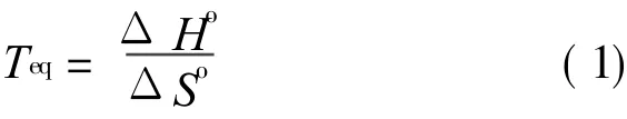
Eq.(1)can be used for most reactions and predicts extremely high values of Teq,as indicated in Table 1,for straight hydrocarbon oxidation as ΔSo≈ 0.Thehigh temperatures indicated in Table 1 for hydrocarbon based fuels are typically above temperature limits for engineering materials.In practical cycles following the Carnot cycle the operating temperatures for combustion are considerably below the equilibrium temperature and the combustion is therefore highly irreversible with considerable entropy generation and limited efficiency.This is the reason why ordinary internal combustion engines have such poor second law performance.Overall efficiency can be boosted using waste heat recovery from the flue gas,nevertheless,even the best current implementations of large scale power generation are limited to a peak efficiency of ca.60%(59.1%verified on an M 701G2 gas turbine at the 1 500 MW Tokyo Electric Kawasaki power station;59%in Irsching 5 in Germany using Siemens SGT5-4000Fgas turbines;61% expected from the MHI J class machines[9]).
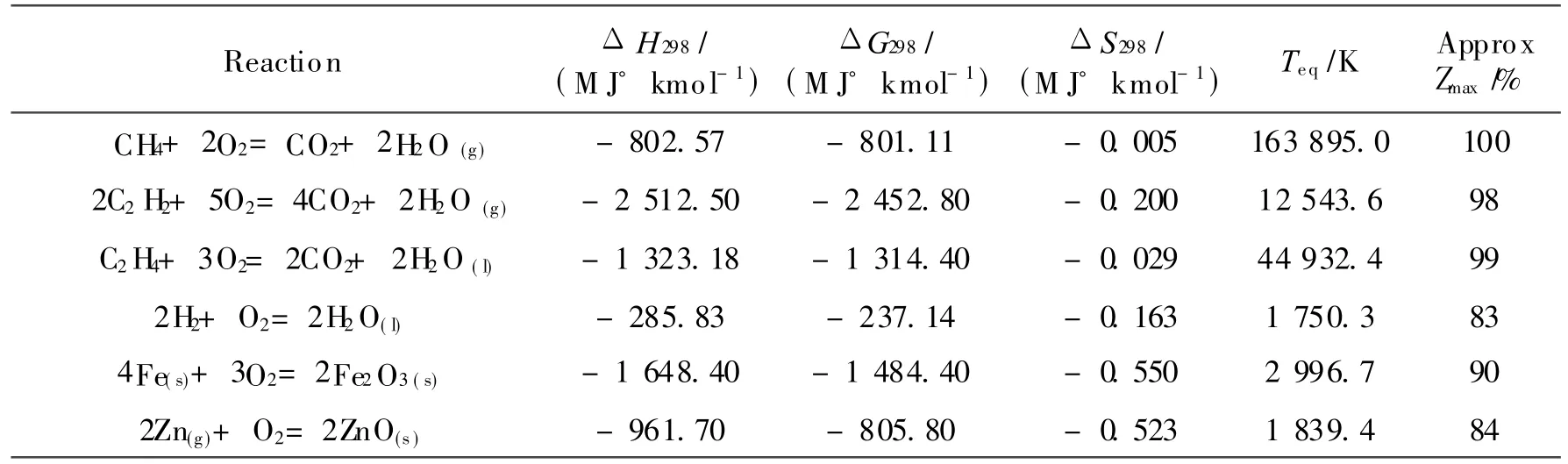
Table 1 Equilibrium temperature data for certain reactions
1 CLC
CLC was originally proposed by Richter and Knoche[10]in order to achieve high thermal efficiency.In CLCa carrier moleculeis used to transport oxygen between two reactions,one where the carrier moleculeis oxidised and another where the carrier moleculeis reduced by reaction with a fuel.Careful selection of the carrier molecule can result in much lower and therefore achievable equilibrium temperatures giving high thermal efficiencies.CLC uses processes comparable to those in the human body for extraction of energy from food but instead of using haemoglobin,simpler metal oxygen carrier molecules are used.
For a generic monovalent oxygen carrier,M,the redox reactions in a CLCsystem,ignoring the argon content of air,are defined by
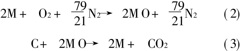
For most metals,their oxidation reaction is highly exothermic.This can provide a high temperature exhaust gas for power production,through say a turbine.Oxide reduction reactions are endothermic requiring addition of heat to the reactor.In order to generate power from CLC,a heat engine,can be″straddled″between the two chemical reactions,receiving heat from the oxidiser and rejecting heat into the reducer.Part of this heat can be used to produce shaft work for power generation.The remainder of the heat is transferred to the reduction reaction.An idealised CLC system following these principles is illustrated in Fig.1.In addition to the main engine shown in Fig.1,there is a small additional heat engine(or heat pump for some hydrocarbons)that rejects a proportion of heat to the surroundings.This heat rejection is necessary in this reversible device,to ensure that the entropy of the surroundings changes by an amount equal and opposite to the standard state entropy, ΔS°,of CH4oxidation.
The practical design of a CLCsystem will depend on a series of factors such as the scale of heat and power to be produced,the technologies available for the reducer and oxidiser,decisions regarding oxygen carrier and valve and power generation technologies,output stream separation and plant scale.Criteria regarding choice of oxygen carrier include:
(1)High reactivity in both redox stages;
(2)High combustion efficiency;
(3)Low fragmentation,attrition and resistance to agglomeration;
(4)Fluidisation and stability under repeated cycles of oxidation and reduction;
(5)Economic viability and environmental suitability.
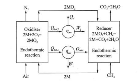
Fig.1 Idealised CLC system for power production usingmethane as fuel

Fig.2 Typical arrangement for CLC based on fluidised bed
A typical arrangement for chemical looping based on a pair of fluidised bed reactors is illustrated in Fig.2(Ref.[11]).In the air reactor(oxidiser)the carrier is oxidised,a cyclone is used to separate out the oxidised carrier from the nitrogen,and the solid particles are delivered to the fuel reactor(reducer)where a reduction reaction takes place prior to thecarrier particles being delivered to the air reactor again and the cycle repeats(Refs.[12-13]).
Carriers can be classified into two principal categories:
(1)A metal combined with an inert material;
(2)A pure metal.
Many forms of metal carrier have been proposed including solid oxygen carriers such as Fe,Ni,Co,active oxides primarily NiO/Ni,CuO/Cu,Mn3 O4/MnO,Fe2O3/Fe3O4 and combined oxides such as CaMnO3.Over 600 types of oxygen carriers have been investigated to identify their suitability for chemical looping[14].Theseare normally combined with inert support materials,such as Al2 O3, TiO2, SiO2, ZrO2,NiAl2 O4,Mg Al2O4,sepiolite,bentonite,Al2 MgO4(Refs.[14-17]).Thecombination of a metal with an inert material can increase ion permeability,enhance fluidisatation,durability and resistance to attrition,provide a larger surface area,maintain pore structureand impede migration of the metal.Advantages for this form of system include continuous operation and useof standard technology.Disadvantages include recirculation of particles with associated compression costs,particle attrition,deactivation of the carrier and equipment erosion and the difficulties associated with gas to solid separation.
If a solid carrier is used the redox reactions need to take place in fluidised beds with the oxygen carrier shuttling between the two redox reactors in a granular form.However,due to construction constraints and ash fouling problems,fluidised beds are often limited to a relatively low temperature,and can become clogged if solid fuels are used with a low ash fusion temperature.Consequently,much of the research conducted on CLC is targeted at″clean″,ash free fuels such as natural gas.Solid phase CLC systems,designed to burn coal,have been proposed,but these remain problematic and limited to modest reactor temperatures.
2 FLUID-PHASE CLC
McGlashan et al.[18-19]have explored the use of a metal circulating in pure and oxidised forms around the CLC cycle.Options considered have included potassium,cadmium,zinc sodium,lead,cobalt,iron,calcium and nickel.Selected properties of these are listed in Table 2[7].Carbon is taken as the fuel,although different hydrocarbons give similar values.Richter and Knoche[10]proposed using cadmium in the gas phase.However,due to the properties of cadmium and its oxide,the carrier would have to be in the vapour or liquid state for at least part of the cycle.Eliminating materials that are highly toxic,rare and expensive or have oxidisation temperatures beyond practical engineering material limits reduces the consideration to potassium,zinc and sodium.McGlashan[7]concluded that using liquid and particularly gas phase carriers maximises the thermodynamic advantage of chemical looping. Mc-Glashan et al.[18-19]proposed using a potassium,sodium or zinc based CLC cycle for high theoretical efficiency,generating hydrogen and power.The advantages of potassium,sodium and zinc are their low toxicity and cost,and that the peak cycle temperatures required in chemical loops using these carriers are within achievable engineering limits.Systems of this type can be described as fluid-phase-chemical-looping-combustion(fluid-phase CLC)systems.By using fluid-phase CLC, separation of the oxygen carrier from thefuel′s ash is facilitated,as the latter can either be floated on a pool of liquid oxide,or,alternatively,separated as a fly ash from a gaseous oxygen carrier using cyclones or filtration.As a result,burning coal(or heavy liquid fuels)is facilitated with theash separated from the carrier species by virtue of a phase difference.An additional advantage of fluid-phase CLCis that a fluidised bed can be avoided and entrained flow reactors used instead.This,in turn enables an increase in peak cycle temperatures with a consequent risein overall plant efficiency.
A possible configuration for fluid phase CLC is illustrated in Fig.3[18].A key aspect of the system is the exploitation of phase difference to achieve separation of species through the cycle.The oxidiser and reducer reactors are arranged so that condensed phases travel downwards with gases upwards.As a result counter-current heat transfer takes place,preheating the reactants and cooling the products.This enables the generation of two hot pressurised working fluids in the oxidiser.One fluid consists of N2saturated with metal vapour,zinc in the scheme illustrated,and the other is a stream of liquid.In the reducer the reactor produces a stream of liquid metal and a stream of almost pure,hot and pressurised CO.The carbon monoxide stream can be converted to CO2 by means of the water gas shift reaction.
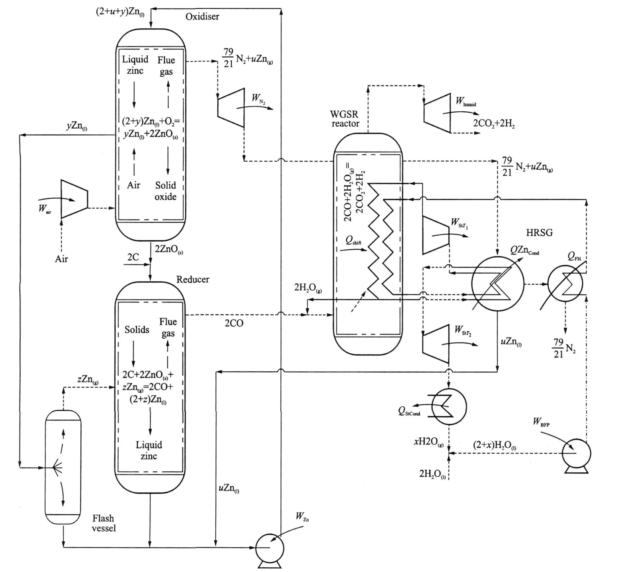
Fig.3 Proposed generic fluid phase CLCpower generation plant
The oxidiser consists of a tubular pressure vessel with a reaction zone located near the reactor′s axis.A stoichiometric excess of liquid metal enters at the top of the reactor.Pressurised air from a compressor enters at the bottom of the reactor.The stream of liquid metal forms droplets that fall through the reactor,under gravity,passing rising hot product gases coming from the reaction zone.Counter-current heat transfer between the streams will occur,preheating the liquid metal while cooling the gas stream.In the reaction zone,only a portion of the liquid metal is oxidised.This oxide agglomerates in the reaction zone,forming a hail of oxide particles or droplets depending on the oxide′s melting point.The oxide particulates fall to the bottom of the reactor through the current of compressed air rising from beneath.Once again,direct contact heat exchange takes place,cooling the oxide,while also preheating the air prior to its entry into the reaction zone.Liquid metal that is not oxidised in the reaction zone,after falling through the upper recuperation region,is collected in an annular trough located adjacent to the reaction zone.Due to the recuperation of heat from the products in the top part of the reactor and also heat received from theoxidation reaction by radiation,the temperature of this pool of liquid metal should approach that of the oxidation reaction.The hot liquid then passes out of the oxidiser,under pressure,and its heat content used to″drive″the endothermic reduction reaction.
A stream of nitrogen saturated with metal vapour at oxidiser pressure leaves the top of the oxidiser,which is then expanded through a turbine.Due to the fall in temperature through the turbine,a portion of the metal vapour in this stream will condense forming liquid metal″moisture″.This liquid metal is collected in a separator at the exit of the turbine and returned to the chemical loop as a stream of liquid.The gases from this turbine, still carrying some metal vapour,are passed to a combined heat recovery steam generator and metal condenser(HRSG),where they are cooled in two stages.In the first stage,the metal vapour is condensed in a coolercondenser,which forms the superheater for abottoming steam cycle.The cooling surface in this part of the HRSGis maintained at a temperature above the melting point of theliquid metal(692 K for Zinc)to avoid blockageof the exchanger.The second part of the HRSGcools thealmost pure nitrogen leaving the first half of the exchanger.The nitrogen from the HRSGis at a temperature approaching ambient as no feed heating is applied to the water substance entering the exchanger.
Here it is assumed that the system fuel is coke,ashless with zero sulphur content,which can essentially be taken as graphite.This simplifies the analysis to illustrate the system function,although other hydrocarbons and carbon based fuels are also suitable,albeit with additional processes and more complex reactions.Taking the fuel as graphite,the system reaction is given by Eq.(4).

The standard state reaction Gibbs function and reaction enthalpy are given by
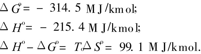
If reaction Eq.(4)is performed in a reversible,steady flow power system,with the species entering or leaving the system separately,and at T o and P o,the maximum″overall efficiency″of the system is given by Refs.[20-21]

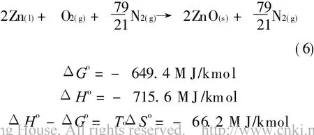
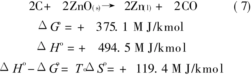
For the oxygen sub-system using zinc as the carrier,CLC sub-system performs two reactions,Eqs.(6,7).
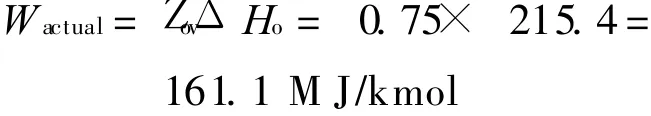
Each of the components of the system illustrated in Fig.3 is analysed assuming a gas compressor polytropic efficiency of 90% and all other efficiencies taken as 85%[18].The corresponding variation of the″overall″efficiency Z ov with P oxi is shown in Fig.4.An oxidation reactor pressure of 35 bar gives an overall efficiency of about 75%.The corresponding maximum turbine inlet temperature at this efficiency point is 1 423 K,which is considerably below the peak operating temperatures already achieved in gas turbine engineering practice indicating the potential for the development of technology operating at these conditions.
Taking the efficiency of the system as 75%from Fig.4,then the actual work output will be given by
Thermodynamics deals with molecular-level systems that are capable of exchanging thermal energy with their surroundings.Entropy is an extensive property that is proportional to the quantity of matter in a system.Entropy can be physically interpreted as a measure of the degree of spreading and sharing of thermal energy within a system.This may involve dispersing thermal energy into a larger volumeof space or sharing energy with previously inaccessible microstates within the system.If a substance becomes more dispersed in space,the thermal energy associated with it will also become spread over a larger volume of space leading to an increasein its entropy.Thermodynamically,for a process that reversibly exchanges a quantity of heat q rev with its surroundings,the entropy change can be defined byΔS=q rev/T,where T is the absolute temperature.In a system characterised by a number of accessible microstates,entropy can be defined by S=k lnΨ,where k is Boltzmann′s constant and K is the number of microstates that corresponds to a macrostate of the system.The thermal energy within a system will attain the most probable macrostate for a given set of conditions.
A key facet of chemical looping is that the two redox reactions operate close to their respective equilibrium conditions.The maximum theoretical work output from a fuel consuming device is limited to the fall in Gibbs function of the fuel′s oxidation reaction[20,22].The ratio between the standard state enthalpy of oxidation(ΔH°)of the oxygen carrier to that of the fuel,is greater than unity for most combinations of oxygen carrier and hydrocarbon.This enables the temperature ratio at which a chemical looping cycle operates to be reduced without sacrificing efficiency.
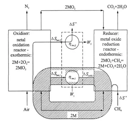
Fig.5 Sankey diagram of entropy fluxes in reversible CLC system
Fig.5 shows the fluxes of entropy,which,importantly,circulate in a reversible CLC system.The entropy change for methane oxidation(and for hydrocarbon combustion in general),is negligible.However,in looping systems,because the oxygen carrier acts as a catalyst,it can be selected so that both redox reactions involve a significant change in entropy,i.e.,|ΔS°|is large.The recirculation of both energy and entropy means that the oxidation and reduction reactions can both exhibit a significant entropy change,ΔS.This means that the entropy ″available″for heat exchange between oxidiser and reducer,through the heat engine,is much larger than in systems without a chemical loop.This is despite the entropy ″flowing through″the system,i.e.,ΔS°for the CH4 oxidation reaction,being small.This is why the two reactions can take place reversibly at relatively low temperatures,while exchanging heat with a practical heat engine.The net heat rejection,Q rej,is close to zero,and as a result the overall efficiency is close to unity as it must be for a reversible hydrocarbon burning system.Such a high efficiency would be impossible using single stage oxidation at the temperatures occurring in this cycle(the two redox reaction take place at 1 839 K and 1 039 K respectively).CLCand the re-circulation of entropy madepossible by its adoption,enables the irreversibility of power systems to be reduced systematically,while maintaining peak cycle temperature at reasonable levels for practical engineering implementation.
Fluid-phase CLC therefore offers the potential to achieve two seemingly conflicting goals:
(1)The effective generation of a separated stream of CO2 and hence the facilitation of its capture;
(2)Combined with an increasein overall system efficiency.
Critically,these two goals are realised using the same capital equipment,a capital investment required whatever method is chosen to capture CO2.
In addition high thermal efficiency and inherent carbon capture,the merits of fluid-phase chemical looping include the lack of requirement for steam condensers and cooling towers.Such equipment is physically large and requires significant capital investment.In addition cooling systems generally require access to a sink temperature for example provided by a river or ocean but this is not a requirementin chemical looping.Fluid-phase CLCis however complex and technically challenging.A heat engineis required to generate work from the redox reactions.If a turbine is used to generate shaft work,a means of generating a hot,pressurised working fluid in the oxidiser is needed,whilst avoiding indirect heat exchange.If as suggested here a stream of zinc oxide vapour or sodium oxide vapour is used then a turbine that is able to sustain the harsh environment of metal oxide vapour/multi-component flow is required.Also heat is required for the reducer to drive the endothermic reaction,again preferably without using indirect heat exchange.It is necessary to separate the oxygen carrier and nitrogen streams in the oxidizer.Each of theseissues represents significant technical challenges which are being addressed in on-going work on practical plant design as indicated in this paper.
3 CONCLUSION
For combustion of hydrocarbons to be performed reversibly in a single reaction,impractically high working temperatures are required.As a result,alternative schemes are necessary in order to achieve high cycle efficiencies for power production.Fluid phase CLC using potassium,zinc or sodium as thecarrier,offers an alternative to traditional power generation systems and is capable of achieving thermal efficiencies of circa 75%.A key facet of chemical looping is that the two redox reactions operate close to their respective equilibrium conditions.The ratio between the standard state enthalpy of oxidation of the oxygen carrier to that of the fuel,is greater than unity for most combinations of oxygen carrier and hydrocarbon.This enables the temperature ratio at which a chemical looping cycle operates to be reduced without sacrificing efficiency.By using fluid-phase CLC,separation of the oxygen carrier from the fuel′s ash is aided.As a result,burning coal or heavy liquid fuels,is facilitated with the ash being separated from the carrier species by virtue of phase difference.
[1] Sims R E H,Schock R N,Adegbululgbe A,et al.Energy supply climate change 2007:Mitigation.Contribution of Working Group III to the Fourth Assessment[C]//Intergovernmental Panel on Climate Change.Cambridge:Cambridge University Press,2007.
[2] International energy agency.World energy outlook 2006[M].Paris:OECD Publication Service,2006.
[3] Enerdata company.A global energy data base including OECD data[M].Grenoble,France:Enerdata,2004.
[4] Price L,de la Ruedu Can S.Sectoral trends in global energy use and greenhouse gas emissions[R].LBNL-56144,2006.
[5] Fisher B.Industry related technology research[C]//Proceedings of the Expert Review Meeting,Intergovernmetnal Panel on Climate Change(IPCC)WG III.Capetown:[s.n.],2006.
[6] Mac Kay D J C.Sustainable energy without the hot air[M].Cambridge:UIT,2009.
[7] McGlashan N R.Chemical looping combustion— a thermodynamic study[J].J Mech Eng Sci,2008,222:1005-1019.
[8] Appleby A J,Foulkes F R.Fuel cell handbook[M].New York:Van Nostrand Reinhold,1989.
[9] Power engineering international.Gas turbines breaking the 60% efficiency barrier[EB/OL].www.powergenworldwide. com/index/display/articledisplay/2278068132/articles/cogeneration-and-on-sitepower-production/volume-11/issue-3/featuatures/gas-turbines-breaking.html,2010-05-01/2010-10-01.
[10]Richter H J,Knoche K F.Reversibility of combustion processes,in efficiency and costing—Second law analysis of processes[J].ACS Symposium Series,1983(235):71-85.
[11]Lyngfelt A,Leckner B,Mattisson T.A fluidised bed combustion process with inherent CO2 separation;application of chemical looping combustion[J].Chemical Engineering Science,2001,56:3103-3113.
[12]Brandvoll O/,Bolland O.Inherent CO2capture using chemical looping combustion in a natural gas fired cycle[J].Trans ASME,2004,126:316-321.
[13]Mattisson T,Garcī-Labiano F,Kronberger B,et al.Chemical-looping combustion using syngas as fuel[J].Int J Greenhouse Gas Control,2007,1:158-169.
[14]Lyngfelt A,Johansson M,Mattisson T.Chemical looping combustion—Status of developmet[C]//9th International Conference on Circulating Fluidised Beds.Hamburg:[s.n.],2008.
[15]Fang H,Haiban L,Zengli Z.Advancements in development of chemical looping combustion:A review[J].International Journal of Chemical Engineering,2009,16:1-16.
[16]Hossain M M,de Lasa H I.Chemical looping combustion(CLC)for inherent CO2 separations—A review[J].Chemical Engineering Science,2008,63:4433-4451.
[17]Dennis JS,Scott SA.In situ gasification of a lignite coal and CO2 separation using chemical looping with a Cu-based oxygen carrier[J].Fuel,2009,89:1623-1640.
[18]McGlashan N R,Childs P R N,Heyes A L,et al.Producing hydrogen and power using chemical looping combustion and water-gas shift[J].Journal of Engineering for Gas Turbines and Power,2010,132:031401-1-10.
[19]McGlashan N R,Childs P R N,Heyes A L.Chemical looping combustion using the direct combustion of liquid metal in a gas turbine based cycle[R].ASME GT2010-23393,2010.
[20]Haywood R W.A critical review of the theorems of thermodynamic availability,with concise formulations,Part 1:Availability[J].J Mech Eng Sci,1974,16:160-173.
[21]Haywood R W.Analysis of engineering cycles—Power,refrigeration and gas liquefaction plant[M].Oxford:Pergamon Press,1991.
[22]Winterbone D E.Advanced thermodynamics for engineers[M]. Oxford:Butterworth-Heinemann,1997.
猜你喜欢
国家教育行政学院学报(2020年11期)2021-01-05
国家教育行政学院学报(2020年7期)2020-09-03
ELLE世界时装之苑(2020年1期)2020-04-17
山东开放大学学报(2019年3期)2019-08-02
照明工程学报(2019年3期)2019-07-09
黑龙江民族职业学院信息(2017年6期)2018-01-03
漯河职业技术学院学报(2017年2期)2017-05-18
———动力工程系
西安航空学院学报(2014年4期)2014-07-13
奇闻怪事(2014年1期)2014-03-22
 Transactions of Nanjing University of Aeronautics and Astronautics2011年1期
- Transactions of Nanjing University of Aeronautics and Astronautics的其它文章
- 拉压、扭转载荷下铸铝合金的亿周疲劳性能研究
- 法国MBDA爆震和连续爆震波发动机的研发
- 端墙形状对蒸汽涡轮效率的影响
- FATIGUE LIFE PREDICTION METHOD FOR IMPACTED LAMINATES
- VIBRATION NUMERICAL ANALYSISOF COUNTER-ROTATING TURBINE WITH WAKE-FLOWUSING FLUID-STRUCTURE INTERACTION METHOD
- EXPERIMENTAL STUDY OF FORCED SHOCK TRAIN OSCILLATION IN ISOLATOR UNDER ASYMMETRIC INCOMING FLOW