
拉压、扭转载荷下铸铝合金的亿周疲劳性能研究
2011-12-02 01:39薛红前吴铁鹰Bathias
薛红前 吴铁鹰 Bathias C
(1.西北工业大学机电学院,西安,710072,中国;2.南京航空航天大学能源与动力学院,南京,210016,中国;3.法国巴黎第十大学能源与动力实验室,维莱德 ,92410,法国)
INTRODUCTION
AS5U3G-Y35 aluminum alloy is highly suitable for high strength cast alloys due to its good flowability of melt and high strength[1].The use of the cast aluminum alloys in automotive or aircraft structural applications is rapidly growing to reduce weight.The aluminum alloy also has the low thermal conductivity and the excellent corrosion resistance which makes it favorable in aircraft engine structural applications.
For aluminum alloys applied to aircraft engine components,there is a need for understanding the fatigue behavior of alloys in thevery high cycle regime.Ultrasonic fatigue instrumentation at frequency of 20 k Hz was used to reduce testing time and examine very long life fatigue behavior[2-5],which validated that it was an effective and reliable way to investigate fatigue properties of materials[5-8].However,much of the available ultrasonic fatigue properties today are axial loading,although some fatigue criterions can be used to predict the torsion fatigue behavior using the axial fatigue life[9-10].Because many components are primarily under torsion loading conditions,the investigation of fatigue behavior for the cast aluminum extends a wider range of test conditions involving axial and torsion loading to understand the fatigue properties and the damagemechanisms of the material beyond 1010cycles.
In this paper,samples of cast aluminum are used for fatigue test in the axial and torsion loading at 35 Hz and 20 k Hz,respectively.The fa-tigue strength and thefracture mechanism of each specimen are also investigated.And the relationship of fatigue strength between in axial loading and torsion loading is discussed.
1 EXPERIMENTS
1.1 Material
The material examined in this paper is 2-AS5U3G-Y35 cast aluminum alloy.The chemical composition is measured by the energy dispersed X-ray spectrometry(EDXS).The results are listed in Table 1,and typical values of mechanical properties are exhibited in Table 2,where E is the Young′s modulus,d thedensity,A the reduction in area,e y theuniaxial yield stress,UTSthe ultimate strength,and HV 30 the hardness.The microstructure of cast aluminum 2-AS5U3G-Y35 is shown in Fig.1.The average grain is 10μm,and a little fine pore(no more than 5μm)is finely dispersed in the microstructure.Solid cylindrical specimens are used with a gauge section of 5 mm in diameter.
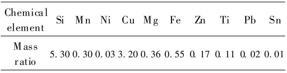
Table 1 Chemical composition(in mass)of cast aluminum 2-AS5U3G-Y35 %
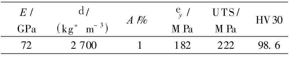
Table 2 Mechanical properties of cast aluminum 2-AS5U3G-Y35

Fig.1 Microstructure of cast aluminum 2-AS5U3G-Y35
1.2 Fatiguetesting method
Fatigue tests are conducted in an ultrasonic fatigue testing machine under the axial or torsion loading at the frequency of 20 k Hz.In the ultrasonic fatigue testing,the specimens are cooled by using the compressed air to decrease the temperature of the testing specimen.And fatigue tests are performed until the failure of a specimen,or up to 1010cycles as run-out.The experimental results are compared with the results obtained at the frequency of 35 Hz using conventional fatigue test machine.
1.3 Ultrasonic fatigue test system for torsion loading
Ultrasonic fatigue test system in axial loading is widely used in the fatigue behavior investigating of material invery high cycle regime[2-6].In order to test the fatigue behavior of materials subjected to cyclic torsion loading to 1010cycles,an ultrasonic torsion fatigue system is designed based on the ultrasonic fatigue system in the axial loading.
In the ultrasonic torsion fatigue test system,the torsion amplifier that transforms the longitudinal vibration to the torsion vibration and the output amplified by the torsion angular displacement is used to supply the shear stress to the specimen.The torsion vibration system is comprised of a converter,a longitudinal amplifier,a torsion amplifier,and a torsion specimen(Fig.2).The torsion amplifier and the specimen have the 20 k Hz torsion resonance length,and the torsion displacement amplitude of the specimen reaches its maximum in the end,while the shear strain excitation attains the maximum in the middle section of thespecimen producing the required high frequency fatigue shear stress.
In this paper,all tests are performed at the stress ratio of R=-1.Prior to the each test,the strain in the center(the maximum strain site)of specimen is calibrated with a strain gage bonded to the gage section.Under the nominal elastic conditions used for loading to very high cycles,there is a linear relationship between the input voltage and the strain in the gage section.A signal amplifier and an oscilloscope are used to measure strain in the gage section.The computerized control unit allows switching from input voltage to stress control during a running test.Cyclic numbers,maximum stress and testing frequency are continuously recorded by the test control software.
1.4 Dynamic analysis
The difference of ultrasonic fatigue test system between in the axial loading and in the torsion loading is that a torsion amplifier is used to supply the torsion angular displacement to the torsion specimen.In order to obtain a reasonable vibration model of the ultrasonic torsion test system,the ultrasonic test setup is modeled by using the finite element software ANSYS.The dynamic vibration displacement analysis of the system is shown in Fig.3,and the maximum torsion displacement at the end of torsion amplifier can be seen from the figure.
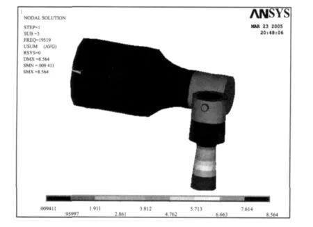
Fig.3 Displacement field in torsion system
2 RESULTSAND DISCUSSION
2.1 High-cycle f atigue properties
Fatigue tests are divided into two kinds of loading type:one is uniaxial tension-compression fatigue with R=-1;another is torsion fatigue with R=-1.Prior to fatigue tests,all specimens are polished and the roughness of specimen is less than 0.2μm,which satisfied the ASTM standard of metallic materials fatigue test.
Conventional fatigue tests(35 Hz)are conducted by the INSTRON fatigue test machine,in which the cycle stress loading is controlled.The fatigue test results are between 104and 107cycles,and by using the ultrasonic fatigue test machine,the 105—1010cycles fatigue data are obtained.
The results from the ultrasonic fatigue test system compared with the results obtained using conventional testing machines areplotted together in Fig.4(R=-1).The results show that many specimens failed in the range of 107—1010cycles.There is no endurance limit existed in the S-N curve of 2-AS5U3G-Y35,and the S-N curve continues to decrease from 107to 1010cycles.

Fig.4 Experimental results of 2-AS5U3G-Y35 in axial loading(R=-1)
Fig.5 shows the S-N curve of cast aluminum 2-AS5U3G-Y35 for torsion fatigue test with R=-1.In Fig.5,the fatigue lifetime increases as the stress amplitude decreases in the life range of 104—107cycles,and the fatigue fracture occurres beyond 107cycles.However,the slope of S-N curve decreases a little.
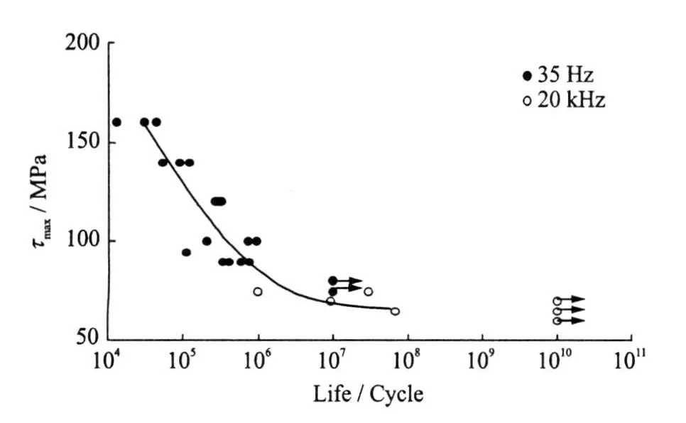
Fig.5 Torsion fatigue test results of 2-AS5U3G-Y35(R=-1)
2.2 Fatigue fracture mechanism
The fatigue crack initiations of most fractured specimens in the axial loading are from the surface or the subsurface voids in the specimens.Fig.6 shows a typical fatigue fracture surface tested at 20 k Hz and an applied maximum stress level of 70 MPa.The topography of the fracture surfaces are found to obtained thevoid at the subsurface of specimen.In the vicinity of crack origin,a zone with a number of pores exists.Fig.7 shows the subsurface fatigue crack initiation tested at the frequency of 20 k Hz with the same applied maximum stress level of 70 MPa.Compared with the fatigue fracture surface in Fig.6,a larger void is in the crack origin.So it has shorter fatigue life with N f=4.47×10⁷cycles than that of the fractured specimen with Nf=1.46×10⁹cycles shown in Fig.6.
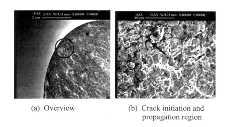
Fig.6 Subsurface fatigue crack initiation of specimen tested with N f=1.46×10⁹ at 20 k Hz
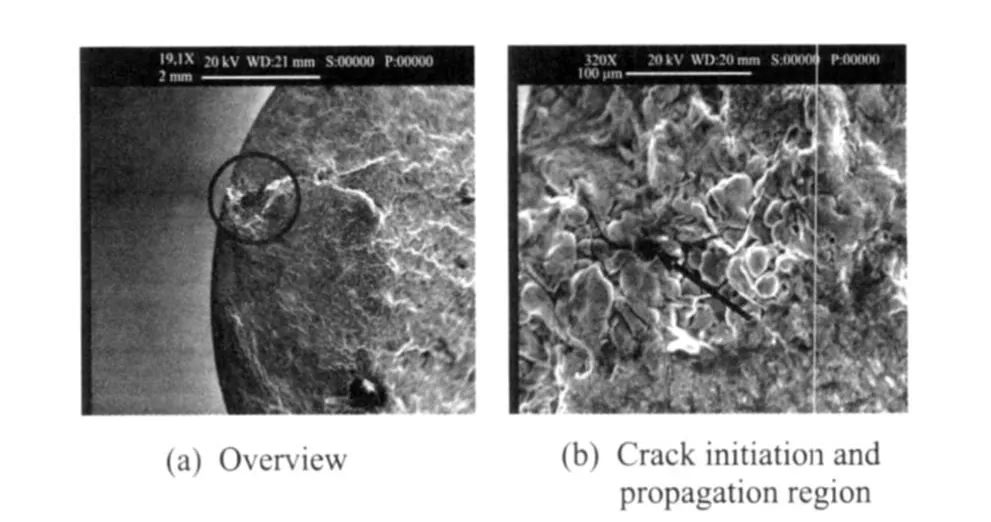
Fig.7 Subsurface fatigue crack initiation of specimen tested with N f=4.47×10⁷ at 20 k Hz
Observed cracks in the torsion fatigue specimens appear on the maximum shear planes.Although in the some cases the overall crack orientation appeares on a typical spiral 45°fracture plane(i.e.,maximum principal stress plane),the fatigue damage mechanism is actually shear.Fatigue crack initiations of all the fractured specimens are from surface of specimens.Fig.8 shows a typical torsion fatigue fracture surface.For the fatigue crack growth in the 45°of axial direction,there are micro-cracks around theprincipal crack.The fatigue crack growth reveals the spiral 45°fracture plane and the fatigue initiation is from the specimen surface.
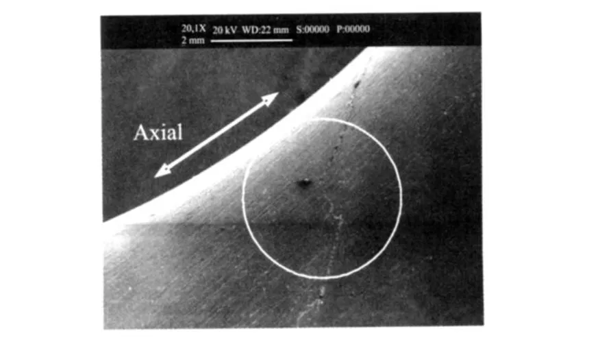
Fig.8 Growth of torsion fatiguecrack
2.3 Discussion
2.3.1 Prediction of shear fatigue properties
Predictions of the torsional fatigue behavior are obtained by using the axial fatigue life data.The shear fatigue properties in the torsional strain-life equation are calculated based on von Mises,Tresca and maximum principal strain criteria respectively.According to thevon Mises criterion[11],we have
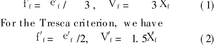
And for themaximum principal strain criterion,we have

The curve of shear stress amplitude versus the fatigue life from experiments and predictions is shown in Fig.9.It can be seen that among the three criteria,the maximum principal strain criterion provides the best estimation of the torsional fatigue behavior.However,none of these criterion results is in a satisfactory prediction.Choosing the Tresca criterion can lead to very poor predictions and a conservative design.

Fig.9 Results of experiments and predictions
2.3.2 Torsion fatigue mechanism in high cycle regime
Under a cyclic torsional loading condition,the fatigue crack initiates from surface of the specimen center subjected to the maximum shear stress.When the fatigue crack initiates,the local stress raises and different stress states exist around the fatigue crack initiation.The tensile stress on the 45°plane exceeds the tensile strength of the alloy before theshear stress reaches the shear strength.The fracture occurs normal to the 45°tensile plane,thus forming a conical fracture surface.
As the loading is axially symmetrical,a fatigue crack can be initiated at any point,or at several points in the center of specimen which shows the maximum shear stress.The multiple cracks do not occur in the same planeand are separated from each other.
It is discovered from examination of fatigue fracture surface that the fracture surface contains the evident shear fatigue strip and the fatigue cracks arising from torsional stresses show beach marks,although in some cases the overall crack orientation appeares on a typical spiral 45°fracture plane(i.e.,maximum principal stress plane).It is also found that the fatigue damage mechanism is in fact shear.
The grow th cracks are oriented at approximately 45°to the axis of specimen,which indicates that the final fracture is caused by a tensile stress normal to the 45°plane,and unlike the expectation of the shear stress causing an overload failure.
3 CONCLUSIONS
From the investigation of fatigue properties of the cast aluminum 2-AS5U3G-Y35 in a very high cycle regime,the following conclusions can be drawn:
(1)Fatigue failure occurrs in the very high cycle regimes for the cast aluminum alloy without fatigue limits and evident frequency effect.The fatigue criterions cannot be used in prediction of torsion fatigue strength using axial fatigue life data.
(2)High cycle fatigue lives are pronounced and determined by fatigue crack initiation.The different fatigue initiation occurs under the different loading condition.For the specimens in the axial loading in high cycle regimes,fatigue crack initiations are often from subsurface or interior defect. Fatigue strength strongly depends on casting defects.If there is no evident microstructure defect,the fatigue crack initiation is also from the specimen surface.
(3)Fatigue crack always initiates from the specimen surface for the torsion fatigue test.The growth cracks are oriented at approximately 45°to the axis of specimen,which indicates that the final fracture is caused by a tensile stress normal to the 45°plane and it is not the expected shear stress causing an overload failure.
[1] Wang Qingyuan,Berand JY,Bathias C.Gigacycle fatigue of ferrous alloys[J].Fatigue&Fracture of Engineering Materials& Structures,1999,22(8):667-672.
[2] Mayer H,Papakyriacou M,Zettl B,et al.Influence of porosity on thefatigue limit of diecast magnesium and aluminium alloys[J].International Journal of Fatigue,2003,25(3):245-256.
[3] Sun Zende,Bathias C,Baudry G.Fretting fatigue of 42Cr Mo4 steel at ultrasonic frequency[J].International Journal of Fatigue,2001,23(5):449-453.
[4] Bathias C.Thereis no infinitefatigue lifein metallic materials[J].Fatigue&Fracture of Engineering Materials&Structures,1999,22(7):559-565.
[5] Murakami Y,Nomoto T,Ueda T.Factors influencing the mechanism of superlong fatigue failure in steels[J].Fatigue&Fracture of Engineering Materials&Structures,1999,22(7):581-590.
[6] Bayrakatar E,Bathias C,Xue Hongqian,et al.On the giga cycle fatigue behaviour of two-phase(T 2+V)Ti Al alloy[J].International Journal of Fatigue,2004,26(2):1263-1275.
[7] Xue Hongqian,Tao Hua,Bathias C.The analysis of specimen design for fatigue test at ultrasonic f requency[C]∥The 3rd International Conference on Very High Cycle Fatigue.Tokyo,Japan:[s.n.],2004:440-447.
[8] Bayrakatar E,Marines I,Bathias C.Failure mechanisms of automotive metallic alloysin very high cycle fatigue range[C]∥Proceeding of the Third International Conference on Very High Cycle Fatigue.Toyko,Japan:[s.n.],2004:124-131.
[9] Davoli P,Bernasconi A,Filippini M,et al.Independenceof the torsional fatiguelimit upon a mean shear stress[J].International Journal of Fatigue,2003,25(6):471-480.
[10]Murakami Y,Takahashi K.Torsional fatigue of a medium carbon steel containing an initial small surface crack introduced by tension-compression fatigue:Crack branching,non-propagation andfatigue limit[J].Fatigue&Fractureof Engineering Materials&Structures,1998,21(12):1473-1484.
[11]McClaflin D,Fatemi A.Torsional deformation and fatigue of hardened steel including mean stress and stress gradient effects[J].International Journal of Fatigue,2004,26(2):773-784.
猜你喜欢
中国机械工程(2022年21期)2022-11-21
中国机械工程(2022年7期)2022-04-20
环球时报(2022-03-08)2022-03-08
数据采集与处理(2021年4期)2021-09-20
艺术大观(2019年21期)2019-10-12
西安航空学院学报(2019年3期)2019-07-26
西北工业大学学报(2016年6期)2017-01-03
西北工业大学学报(社会科学版)(2014年2期)2014-02-27
雕塑(2009年5期)2009-11-30
环球时报(2009-09-21)2009-09-21
 Transactions of Nanjing University of Aeronautics and Astronautics2011年1期
- Transactions of Nanjing University of Aeronautics and Astronautics的其它文章
- 端墙形状对蒸汽涡轮效率的影响
- 使用液态化学循环的高热效率动力研究
- 法国MBDA爆震和连续爆震波发动机的研发
- FATIGUE LIFE PREDICTION METHOD FOR IMPACTED LAMINATES
- VIBRATION NUMERICAL ANALYSISOF COUNTER-ROTATING TURBINE WITH WAKE-FLOWUSING FLUID-STRUCTURE INTERACTION METHOD
- EXPERIMENTAL STUDY OF FORCED SHOCK TRAIN OSCILLATION IN ISOLATOR UNDER ASYMMETRIC INCOMING FLOW