
Investigation of flow characteristics over the fuselage airbrake
2012-04-15 10:54DONGChaoWANGYankuiDENGXueyingSHIWei
实验流体力学 2012年1期
DONG Chao,WANG Yan-kui,DENG Xue-ying,SHI Wei
(Institute of Fluid Mechanics,Beijing University of Aeronautics and Astronautics,Beijing 100191,China)
0 Introduction
The airbrake on the leeward side of the fuselage is typically designed to reduce the speed,decrease the turning radius and enhance the maneuverability for the modern fighter aircraft.It is consistent with the surface of the fuselage while closed.It breaks the streamline shape of the aircraft and increases the frontal area while opened by the hydraulic actuation system.In order to get rid of the enemy aircraft rapidly and hold an advantaged position in the air fight,it is necessary for the aircraft to decelerate quickly and turn the head in a small radius.So the airbrake on the leeward side of the fuselage is widely used on the third generation high agility fighter aircrafts,such as the British EF-2000,the Russian Su-27and the American F-15,as shown in Fig.1.

Fig.1 Modern fighter aircrafts with the airbrake on the fuselage图1 采用机身减速板方案的现役战斗机
The hinge moment is an important performance guide line for design of the airbrake controlling system.A high moment output is requested for the controlling system if the hinge moment of the aircraft is large which will bring extra weight and structure to the aircraft.So it is important to study the characteristics of the hinge moment of the fuse-lage airbrake.It is still unknown which one is the main contribution part to the hinge moment,the windward side or the leeward side.So it is essential to study the connection between the hinge moment and the flow structures on both the leeward side and the windward side of the airbrake.
The fuselage with chined edges is widely used in the fourth generation aircraft to reduce the radar cross section (RCS)and enhance lift[1-2].A strong forebody vortices flow exists on the chined fuselage at high angles of attack[3].The velocity of the vortex core is nearly three times to the free stream[4-5].It could be speculate that the forebody vortices flow acting on the windward side of the airbrake may contribute to the hinge moment of the airbrake.Breitsamter[6]found that a couple vortices existed on the leeward side of the airbrake at large angles of attack.It could be speculate that the vortices may induce a negative pressure zone on the leeward side of the airbrake and contribute to the hinge moment of the airbrake.
The purpose of this paper is to study the characteristics of the hinge moment of the fuselage airbrake and the flow structures on the windward side and the leeward side of the airbrake,familiar investigations and reports have not been found yet.
1 Experimental setup
Fig.2shows a chined fuselage model with a slenderness ratio of 6.6to the afterbody width D.The airbrake is set at the section of x/D=1.82,the opening angle of the airbrakeδBis 60°.A pressure measurement section is set at the section of x/D=1.45to monitor the flow structure over the forebody.Fig.3shows the position of pressure taps and the abscissa of pressure distribution.For the leeward side of the forebody,the abscissa of pressure tap is defined as 2y/b,which is the ratio of its y-axis coordinate to half-width of local cross-section b/2.For the windward side of the forebody,the abscissa of pressure tap is defined as-2-2y/band 2-2y/bfor left and right side.
Fig.4shows the position of pressure taps on the airbrake.The windward and leeward side of the airbrake has two pressure sections respectively.The abscissa of pressure distribution is defined as x′/H from the rotation axis to the top of the airbrake.The hinge moment of the models are obtained by integrating the pressure from both the windward side and the leeward side of the airbrake.
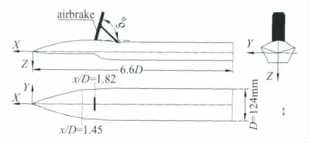
Fig.2 The chined fuselage model with the airbrake图2 带减速板的非常规机身模型

Fig.3 Pressure measurement section at x/D=1.45图3 x/D=1.45测压截面

Fig.4 Position of pressure taps at the windward and leeward sides of the airbrake图4 减速板迎风侧及背风侧测压孔位置
The pressure measurement equipment is a PSI 9816electronic scanivalve system with transducers full scale of 1PSI and accuracy of 0.05%.Spatial velocity and vorticity field are measured by a Dantec PIV system.The scheme of PIV system on the leeward side of the airbrake is shown in Fig.5.The laser is perpendicular to the leeward side of the airbrake;the camera is parallel to the laser.All the PIV result of the airbrake is from the airbrake leeward side section of x′/H=0.6,as shown in Fig.4.
The experiment was carried out in the D-4wind tunnel of Beihang University.It is a low speed,low turbulence level wind tunnel with an open jet test section of 1.5m×1.5m.The experiment wind speed is 40m/s.The Reynolds number is 3.4×10⁵based on the afterbody width D.The opening angle of the airbrake is defined asδB.The fuselage angle of the airbrake is defined asα.

Fig.5 The scheme of the PIV system for the leeward section of the airbrake图5 减速板背风侧流场拍摄示意图
2 Experimental results and discussions
2.1 The characteristics of the hinge moment of the airbrake with angles of attack
As shown in Fig.6,the characteristics of the hinge moment of the airbrake(Cb)can be classified into three regions withα:(1)constant region(0°~16°);(2)nonlinear increasing region (16°~32°);(3)nonlinear decreasing region(32°~70°).Withα increasing,the hinge moment changes little in the constant region,increases greatly in the nonlinear increasing region,and reduces gradually in the nonlinear decreasing region.

Fig.6 The characteristics of the hinge moment coefficients withα,δB=60°,α=0°~70°,Re=3.4×10⁵图6 减速板铰链力矩系数随机身迎角变化曲线,δB=60°,α=0°~70°,Re=3.4×10⁵
The windward hinge moment(Cb1)and the leeward hinge moment(Cb2)of the airbrake are obtained by integrating the pressure on the windward side and the leeward side respectively.The characteristics and the flow structures on both the leeward side and the windward side of the airbrake are discussed in the following sections.
2.2 Flow characteristics of the airbrake in different flow regions
2.2.1 Constant region of the hinge moment
In the constant region(0°~16°),the windward hinge moment decreases linearly and the leeward hinge moment increases linearly,two opposite trends counteract with each other,so the hinge moment of the airbrake changes little withαincreasing in this region,as shown in Fig.6.
Fig.7shows that the pressure distributions are platform shapes on the leeward side of the forebody section-x/D=1.45in the range of 0°~16°,which means that there are no vortices or separations existing over the forebody in this region.The flow over the forebody is an attachment flow.
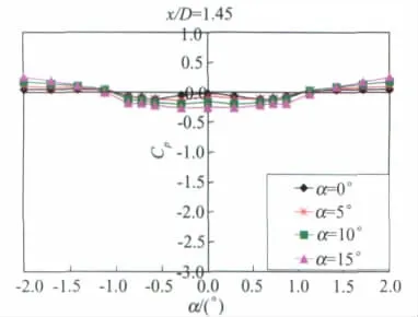
Fig.7 Pressure distributions of x/D=1.45,α=0°~15°,Re=3.4×105图7 x/D=1.45截面压力分布曲线,α=0°~15°,Re=3.4×105
The positive pressures on the windward side of the airbrake reduce gradually withαincreasing in this region,as shown in Fig.8.So the windward hinge moment decreases linearly withαincreasing in this region,as shown in Fig.6.

Fig.8 Pressure distributions on the windward side of the airbrake,δB=60°,α=0°~16°,Re=3.4×10⁵图8 减速板迎风侧压力分布曲线,δB=60°,α=0°~16°,Re=3.4×10⁵
The free sheer layers separate at the side edges of the airbrake and form a weak couple vortices flow on the leeward side of the airbrake in the range of 4°~16°,as shown in Fig.9.Withαincreasing,the vorticity value of the vortex core(solid line)increases a little and the distance from the vortex core to the airbrake(dash line)reduces a little in this region,as shown in Fig.10.It indicates that the couple vortices on the leeward side of the airbrake enhances gradually withαincreasing in this region.So the negative pressures on the leeward side of the airbrake induced by the vortices increase slowly withα increasing in this region,as shown in Fig.11and the leeward hinge moment increases gradually with αincreasing in this region,as shown in Fig.6.

Fig.9 Vorticity and streamline field on the leeward side of the airbrake,x′/H=0.6,δB=60°,α=4°~16°,Re=3.4×105图9 减速板背风侧流线及涡量图,x′/H=0.6,δB=60°,α=4°~16°,Re=3.4×105
2.2.2 Nonlinear increasing region of the hinge moment
In the nonlinear increasing region (16°~32°),withαincreasing,the windward hinge moment decreases linearly and the leeward hinge moment in-creases greatly,the hinge moment is mainly contributed from the leeward side of the airbrake,so the hinge moment of the airbrake increases greatly with αincreasing in this region,as shown in Fig.6.

Fig.10 The vorticity(ωx′)value of the vortex core and the distance(L)from the left vortex core to the airbrake withαincreasing,x′/H=0.6,δB=60°,α=4°~16°,Re=3.4×105图10 减速板背风侧左侧旋涡涡核涡量值和涡位随迎角变化曲线,x′/H=0.6,δB=60°,α=4°~16°,Re=3.4×105
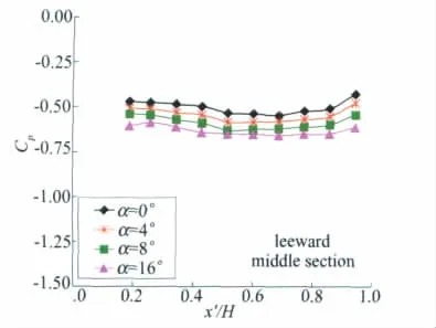
Fig.11 Pressure distributions on the leeward side of the airbrake,δB=60°,α=0°~16°,Re=3.4×10⁵图11 减速板背风侧压力分布曲线,δB=60°,α=0°~16°,Re=3.4×10⁵
Fig.12shows that the pressure suction peaks appear on the leeward side of the forebody sectionx/D=1.45at the angle of attack 17.5°.The pressure suction peaks enhance gradually withαincreasing and move to the symmetry plane of the forebody.It indicates that the forebody vortices generate and develop gradually in this region.

Fig.12 Pressure distributions of x/D=1.45,α=15°~32.5°,Re=3.4×105图12 x/D=1.45截面压力分布曲线,α=15°~32.5°,Re=3.4×105
Fig.13shows the flow structure on the airbrake section-x/D=1.82at the angle of attack 32.5°.It can be seen that the forebody vortices are close to the chine edges of the fuselage when the airbrake is closed(δB=0°)and move to the chine edges of the fuselage when the airbrake is open(δB=60°).The forebody vortices could not be blocked by the airbrake in this region and flow to the downstream from the side edges of the airbrake.

Fig.13 Flow structure of x/D=1.82,δB=0°and 60°,α=32.5°,Re=3.4×10⁵图13 减速板截面x/D=1.82背风侧涡量云图及流线图,δB=0°和60°,α=32.5°,Re=3.4×105
The positive pressures on the windward side of the airbrake reduce gradually withαincreasing in this region,as shown in Fig.14.So the windward hinge moment decreases linearly withαincreasing in this region,as shown in Fig.6.

Fig.14 Pressure distributions on the windward side of the airbrake,δB=60°,α=16°~32°,Re=3.4×10⁵图14 减速板迎风侧压力分布曲线,δB=60°,α=16°~32°,Re=3.4×10⁵
The sheer layers separate at the side edges of the airbrake and form a strong couple vortices flow on the leeward side of the airbrake in the range of 16°~32°,as shown in Fig.15.Withαincreasing,the vorticity value of the vortex core(solid line)increases rapidly and the distance(dash line)from the vortex core to the airbrake reduces markedly in this region,as shown in Fig.16.It indicates that the couple vortices on the leeward side of the airbrake enhance steeply in this region.So the negative pressure on the leeward side of the airbrake induced by the vortices increases greatly withαincreasing in this region,as shown in Fig.17,and the leeward hinge moment increases dramatically withαincreasing in this region,as shown in Fig.6.

Fig.15 Vorticity and streamline field on the leeward side of the airbrake,x′/H=0.6,δB=60°,α=16°~32°,Re=3.4×105图15 减速板背风侧流线及涡量图,x′/H=0.6,δB=60°,α=16°~32°,Re=3.4×105

Fig.16 The vorticity(ωx′)value of the vortex core and the distance(L)from the left vortex core to the airbrake withαincreasing,x′/H=0.6,δB=60°,α=16°~32°,Re=3.4×105图16 减速板背风侧旋涡涡核涡量值和涡位随迎角变化曲线,x′/H=0.6,δB=60°,α=16°~32°,Re=3.4×105
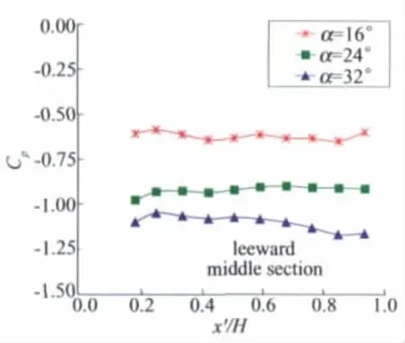
Fig.17 Pressure distributions on the leeward side of the airbrake,δB=60°,α=16°~32°,Re=3.4×10⁵图17 减速板背风侧压力分布曲线,δB=60°,α=16°~32°,Re=3.4×10⁵
2.2.3 Nonlinear decreasing region of the hinge moment
As shown in Fig.6in the nonlinear decreasing region(32°~70°):(1)the hinge moment of the airbrake decreases suddenly in the range of 32°~36°,because the leeward hinge moment decreases steeply;(2)the hinge moment of the airbrake increases in the range of 36°~44°,because the windward hinge moment increases greatly;(3)the hinge moment of the airbrake decreases in the range of 44°~70°,because the windward hinge moment decreases gradually in this region.
Fig.18shows that the pressure suction peaks grow greatly and move to the symmetry plane of the fuselage on the leeward side of the forebody section-x/D=1.45in the range of 32.5°~47.5°.It indicates that the forebody vortices are enhanced and fully developed in this region.

Fig.18 Pressure distributions of x/D=1.45,α=32.5°~47.5°,Re=3.4×105图18 x/D=1.45截面压力分布曲线,α=32.5°~47.5°,Re=3.4×105
Fig.19shows that the flow structure on the airbrake section-x/D=1.82atα=40°.It can be seen that the forebody vortices are close to the symmetry plane of the fuselage when the airbrake is closed(δB=0°)and disappear when the airbrake is open (δB=60°).The forebody vortices could be blocked by the airbrake and fully breakdown in this region.

Fig.19 Flow structure of x/D=1.82,δB=0°and 60°,α=40°,Re=3.4×10⁵图19 减速板截面x/D=1.82背风侧流动结构比较,δB=0°和60°,α=40°,Re=3.4×105
The incoming flow acting on the windward side of the airbrake is an enhanced vortices flow in the range of 32°~44°.So the positive pressures on the windward side of the airbrake increase greatly with αincreasing in this region,as shown in Fig.20and the windward hinge moment increases withαincreasing in this region,as shown in Fig.6.

Fig.20 Pressure distributions on the windward side of the airbrake,δB=60°,α=32°~44°,Re=3.4×10⁵图20 减速板迎风侧压力分布曲线,δB=60°,α=32°~44°,Re=3.4×10⁵
The flow on the leeward side of the airbrake turns to a low speed reattachment flow atα=36°,as shown in Fig.21.So the negative pressure on the leeward side of the airbrake induced by the vortices decreases greatly in the range of 32°~36°,and the leeward hinge moment decreases greatly in the range of 32°~36°.The negative pressure decreases slowly in the region of 36°~44°as shown in Fig.22.So the leeward hinge moment decreases slowly in the region of 36°~44°,as shown in Fig.6.

Fig.21 Vorticity and streamline field on the leeward side of the airbrake,x′/H=0.6,δB=60°,α=36°,Re=3.4×105图21 减速板背风侧流线及涡量图,x′/H=0.6,δB=60°,α=36°,Re=3.4×105
Fig.23shows that the pressure suction peaks reduce gradually and disappear on the leeward side of the forebody section-x/D=1.45in the range of 47.5°~70°.It means that the forebody vortices weaken gradually and breakdown in this region.

Fig.22 Pressure distributions on the leeward side of the airbrake,δB=60°,α=32°~44°,Re=3.4×10⁵图22 减速板背风侧压力分布曲线,δB=60°,α=32°~44°,Re=3.4×10⁵

Fig.23 Pressure distributions of x/D=1.45,α=47.5°~70°,Re=3.4×105图23 x/D=1.45截面压力分布曲线,α=47.5°~70°,Re=3.4×105
The incoming flow acting on the windward side of the airbrake is a weakened vortices flow in the range of 44°~70°.So the positive pressures on the windward side of the airbrake decrease gradually in this region,as shown in Fig.24and the windward hinge moment decreases in the region,as shown in Fig.6.
The negative pressure on the leeward side of the airbrake induced by the vortices decreases slightly in the range of 44°~70°as shown in Fig.25 and the leeward hinge moment decreases slowly in the range of 44°~70°as shown in Fig.6.
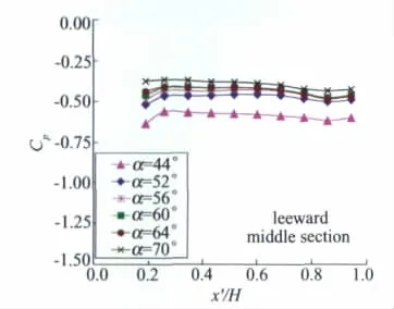
Fig.25 Pressure distributions on the leeward side of the airbrake,δB=60°,α=44°~70°,Re=3.4×10⁵图25 减速板背风侧压力分布曲线,δB=60°,α=44°~70°,Re=3.4×10⁵
3 Conclusions
The flow characteristics over the fuselage airbrake have been investigated in this paper,the results are as follows:
(1)The characteristics of the hinge moment with angles of attack can be classified into three regions:constant region(α=0°~16°),nonlinear increasing region (α=16°~32°),and nonlinear decreasing region(α=32°~70°).
(2)In the constant region (α=0°~16°),the hinge moment of the airbrake changes little withα increasing,because the positive pressure decreases on the windward side of the airbrake and the negative pressure increases on the leeward side of the airbrake,two opposite trends counteract with each other.
(3)In the nonlinear increasing region (α=16°~32°),the hinge moment of the airbrake increases greatly withαincreasing,because the hinge moment is mainly contributed from the leeward side of the airbrake and the negative pressure increases markedly on the leeward side of the airbrake due to the enhanced couple vortices on the leeward side of the airbrake.
(4)In the nonlinear decreasing region(α=32°~70°),the hinge moment of the airbrake decreases greatly in the range of 32°~36°because the vortices flow on the leeward side of the airbrake turns to a low speed reattachment flow atα=36°;the hinge moment of the airbrake increases in the range of 36°~44°because the positive pressure on the windward side of the airbrake increases greatly due to the enhanced forebody vortices flow acting on the windward side of the airbrake;the hinge moment of the airbrake decreases gradually in the range of 44°~70°because the pressure values on the windward side of the airbrake decreases gradually due to the weakened forebody vortices flow acting on the windward side of the airbrake.
[1] JEANS T L,McDANIEL D R,CUMMINGS R M,et al.Aerodynamic analysis of a generic fighter with a chine fuselage/delta wing configuration using delayed detached-eddy simulation[R].AIAA 2008-6228,2008.
[2] TIAN Wei,DENG XueYing.Study on flow behavior and structure over chined fuselage at high angle of attack[J].ACTA Mechanica Sinica,2010,53(8):2057-2067.
[3] MANGE R L,ROOS F W.The aerodynamics of a chined forebody[R].AIAA 1998-2903,1998.
[4] ROOS F W,KEGELMAN J T.Aerodynamic characteristics of three generic forebodies at high angles of attack[R].AIAA-91-0275,1991.
[5] HAYASHI Y,NAKAYA T.Leading-edge vortex on delta wings and its breakdown phenomenon[J].Journal of the Japan Society for Aeronautical and Space Science,1972,20(226):31-37.
[6] CHRISTIAN BREITSAMTER,ARNE SCHMID.Airbrake-induced fin-buffet loads on fighter aircraft[J].Journal of Aircraft,2008,45(5):1619-1630.
猜你喜欢
石材(2022年3期)2022-06-01
石材(2022年3期)2022-06-01
施工技术(中英文)(2022年7期)2022-04-28
中国农村水利水电(2021年2期)2021-03-05
北京航空航天大学学报(2020年3期)2021-01-14
铁道建筑(2020年7期)2020-08-03
科学导报·学术(2020年19期)2020-07-09
铁道建筑(2020年5期)2020-06-20
中成药(2019年12期)2020-01-04
能源研究与信息(2018年1期)2018-05-08

- 实验流体力学的其它文章
- 《实验流体力学》征稿简则