
High-gain planar TEM horn antenna fed by balanced microstrip line
2012-08-13 09:16LINShuZHANGXinyueZHANGXingqiZHANGXueyingCAIRunnanHUANGGuanlong
关键词:张馨
LIN Shu,ZHANG Xin-yue,ZHANG Xing-qi,ZHANG Xue-ying,CAI Run-nan,HUANG Guan-long
林 澍, 张馨月, 张兴起, 张雪莹, 蔡润南, 黄冠龙
(1.Electronic Science and Technology Post-doctoral Research Center,Harbin Institute of Technology,Harbin 150080,China;2.School of Electronics and Information Engineering,Harbin Institute of Technology,Harbin 150080,China)
With the extension of the frequency spectrum of wireless instruments,the demand for the bandwidth of antenna is increasing,and the research of ultra-wideband antenna has been brought to public attention.The ultra-wideband antenna has a rather wide impedance bandwidth to reduce the quantity of the antennas and the volume of the communication instrument by sharing the same antenna among several communication systems.What’s more,the development of the UWB technology impels further researches on the time-domain characteristics of the ultra-wideband antenna.Current ultra-wideband antennas mainly include log-periodic antenna,archimedean spiral antenna,equiangular spiral antenna,bow-tie antenna,tapered slot antenna,and traditional TEM horn antenn[1-6],etc.While the traditional TEM horn antenna is stereo-structure with relative big volume and heavy weight,which fails to benefit the integrating of the communication system.The rest can be designed into printed types to reduce the section and the volume,thus planarization of the antenna can be achieved.The radiation models of the Archimedean spiral antenna and the equiangular spiral antenna are bidirectional circular polarization radiation.Therefore,the antenna’s section will be increased as the metal reflector is added to attain one-way radiation.Bow-tie antenna has a structure of omnidirectional liner polarization radiation,and array constitution or additional reflectors are needed to realize the directional radiation which will introduce a complex feeding network.The log-periodic antenna is usually fed from the short dipole side to realize the directional radiation by using the method of overlapping feeding.Howbeit,it will introduce a length of coaxial line which will restrict the application in the millimeter-wave and the integrated circuits.Additionally,tapered slot antenna is a planar printed type of antenna which is usually composed of feeding network and radiator.And the plane figure of the radiator is similar to the projection on the E plane of TEM horn antenna with adding ridge.Thereby,the tapered slot antenna can be viewed as planar TEM horn antenna.According to the different tapered forms of the slot lines,these antennas can be divided into ViValdi antenna and LTSA antenna[7],etc,all of which have relatively complex structures of ultra-wideband and balanced feeding.
A printed TEM horn antenna with high gain fed by balanced microstrip line is proposed in this paper.The radiation part of the antenna consists of two symmetrical triangular metal slice branches printed on the FR-4 substrate with 1.5 mm thickness.The two branches are fed by balanced microstrip line.The antenna is simulated and the parameters are obtained by software CST MICROWAVE STUDIO®.The simulation and experiment results indicate that the operating frequency of the antenna is from 1.64 GHz to 5 GHz,the antenna has a stable directional radiation characteristics and the feeding structure is simple.The detailed analysis of the simulation and the results of the experiment are presented in the paper.
1 Design of the Antenna
The geometrical configuration of the proposed antenna with relevant structural parameters is shown in Fig.1.The whole antenna can be divided into the feeding part and the radiation part,among which the radiation part consists of metal radiator and medium focusing part.The medium focusing part is the novel structure introduced into planar TEM horn antenna in this paper by which the electronic field energy density can be enhanced,thus the antenna gain can be greatly increased.The design of the metal radiator can be calculated according to formula(1)[8],and the value gained can be set as the seminal values of the simulation.
Then 3.8≤ εr≤9.8,0.006≤ h/λ0≤0.060 and 0.0015≤ W/λ0≤0.075,
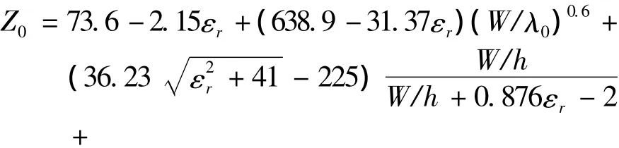
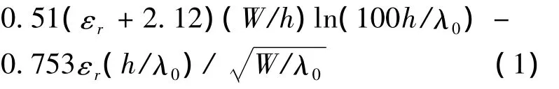
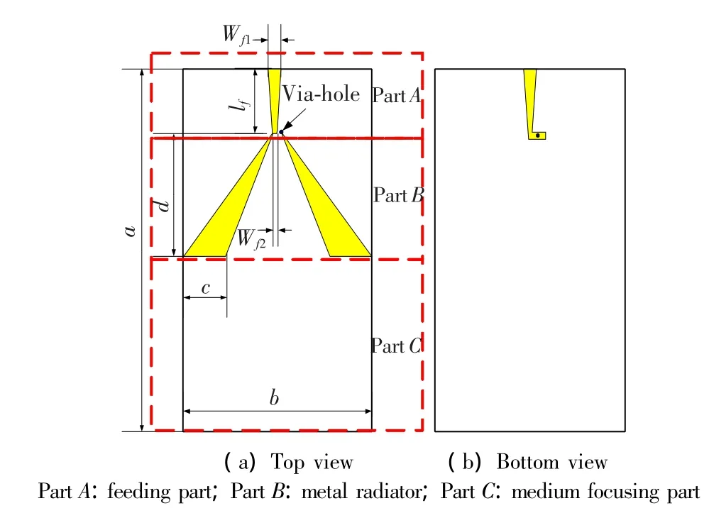
Fig.1 Sketch of the proposed antenna
The feeding part is a balanced microstrip line and the original port impedance of the feed port is 50 Ω.Moreover,the port impedance of the joint between the terminal of the feeding line and the antenna should match the importing port,and the input impedance can be calculated as tapered slot line,so the result is 200 Ω.Thus the balanced microstrip line should also be designed as a tapered form,the major parameters of which depend on the ratio of the width and the height,and the relative permittivity of the dielectric substrate slab,which can be achieved by referring to the method of calculating characteristic impedance of microstrip line.Therefore,the fundamental parameters of the antenna are presented in Tab.1.
Tab.1 Antenna parameters
2 Simulation Analysis
2.1 Ultra-wideband Characteristics
The antenna model,set up according to the structure in Fig.1 and parameters in Tab.1,is simulated by CST MICROWAVE STUDIO®.The simulation results of the surface current density on the antenna radiation feeding line,as shown in Fig.2,indicate that the surface current is a wideband traveling current,which consequently reflect the ultra-wideband characteristics of the antenna.Besides,the simulation results of reflection coefficient are shown in Fig.2,which indicate that the operating bandwidth is from 1.64 GHz to 5 GHz with reflection coefficient less than-6 dB,and the ultra-wideband characteristics of the antenna are shown as well.The feeding line of the antenna is the TEM wave transmission line,and the radiator of the antenna can be regarded as expanding gradually from the slot line,which is the TEM wave transmission line as well.As the TEM wave transmission line is an ultrawideband transmission line and the feeding structure of the whole antenna can be regarded as“Tapered balance microstrip line to Tapered slot line to free space”,three parts of which are all ultra-wideband,and the antenna possesses the ultra-wideband characteristics.
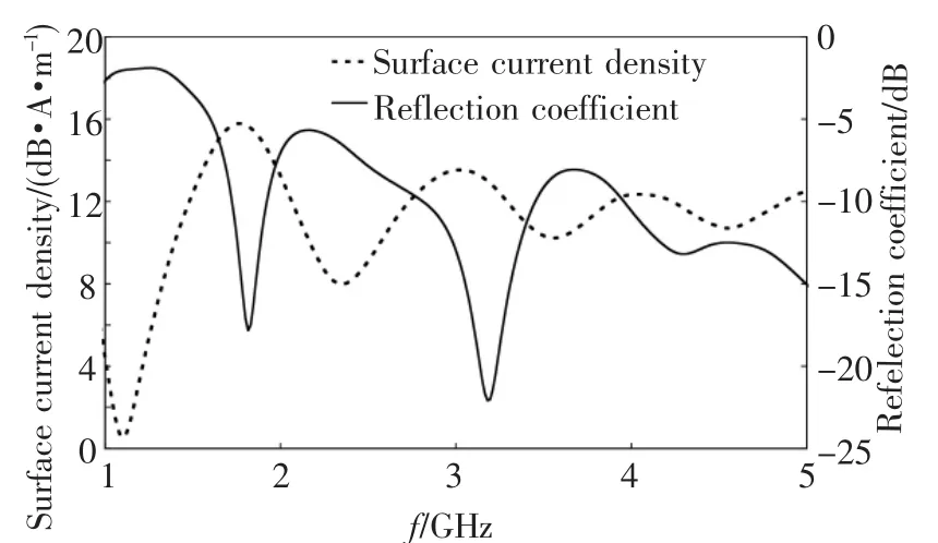
Fig.2 Surface current density and reflection coefficient on the feeder line of the antenna
2.2 Directional Radiation Characteristics
The surface current distribution on the antenna conductor shown in Fig.3 indicates that the current on the surface of the antenna metal radiator is distributed as standing wave.As this distribution is similar to the surface current distribution of half-wave dipole antenna which works at the same frequency,the radiation characteristics of half-wave dipole array can be used to describe the radiation characteristics of the antenna in this paper.
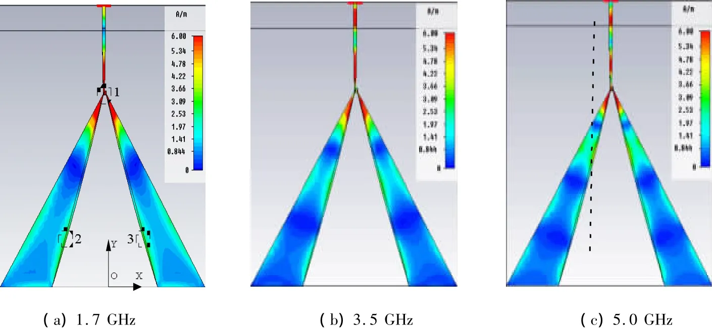
Fig.3 Current distribution on the metal surface of the antenna
Take Fig.3(a)as an example,the antenna is equivalent to the array composed of three pairs of halfwave dipoles,which is shown by symmetry dipoles numbered from 1 to 3 in Fig.4(a).The 1.7 GHz radiation pattern of the array composed of half-wave dipoles 1 to 3 and the planar TEM horn are presented in Fig.4(b)and Fig.4(c)respectively.The three units of this array are fed independently in the simulation;the amplitude and phase of the feeding part are respectively amplitude and phase of the current density at wave loop points 1-3 of the antenna metal surface acquired in the simulation.By comparison,the radiation patterns,except for the difference of the back-lobe,are similar to each other,and they can be equivalent.As the dipole array unit is slant-set,the radiation is asymmetrical and there will be directional radiation in-y direction.Besides,the feeding phases of dipole array are different,and the phase of buckling dipole 1 is advancer than the phases of the inclined dipoles 2 and 3.According to the array antenna theory,the antenna array composed of dipoles 1-3 will produce directional radiation in-y direction.To sum up,the whole antenna will produce directional radiation in-y direction.

Fig.4 Comparison between the equivalent dipole array and the planner TEM horn antenna
2.3 High-gain Characteristics
The simulation is conducted on the length of the dielectric slab in the radiation direction,focusing on its influence on antenna gain,and the results are presented in Fig.5.According to the results,antenna gain is obviously improved after lengthening the dielectric slab.And the length of the dielectric slab and antenna gain are positive correlated.The value of the length of the dielectric slab is 100 mm for the proposed antenna in this paper.Besides,this method of improving gain has no influence on the antenna wideband in the simulation process.
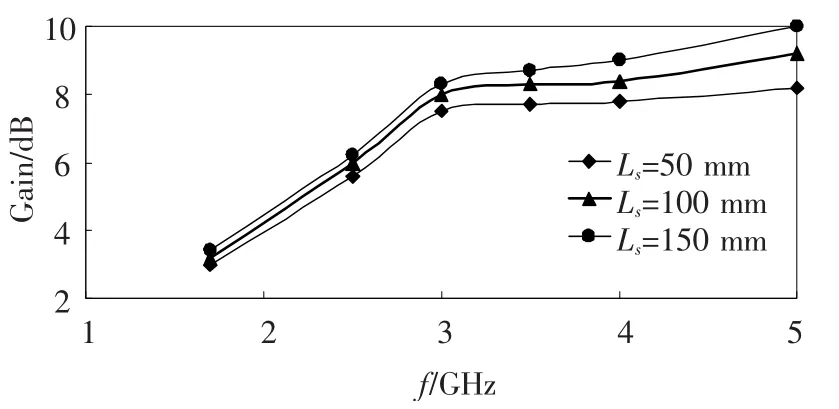
Fig.5 Effects of antenna gain with varying length Lsof the extended dielectric slab
2.4 Influence of Loaded Metal Disc in the Radiation Direction
Structure of antenna with loaded metal disc is shown in Fig.6.The loaded disc in this paper is a new structure introduced into the design of the proposed antenna.As such structure is able to generate induced current on its surface and introduce additional electromagnetic radiation,thus the proposed antenna’s performance is improved.

Fig.6 Sketch of the proposed antenna
Introducing the loaded disc can improve the antenna’s impedance characteristic.Thus,the disc radiuses are separately selected as r=5,10 and 15 mm to simulate antenna’s reflection coefficient,which is set as a goal to attain the best radius.The position relation of the disc and triangular branches will also influence the antenna’s impedance characteristics.Because the antenna’s radiation should be in+y direction,so the center of the disc is selected along y-axis.With the selected distances(dy= -10,0 and 10 mm),the antenna’s reflection coefficient is simulated to attain the best value of dy.The above two set simulation results are shown in Figs.7 and 8.
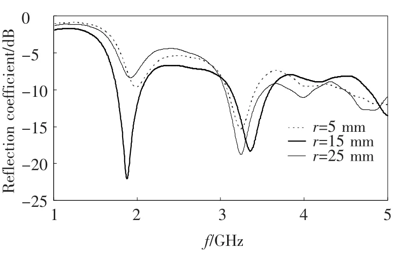
Fig.7 Influence of the loaded disc’s radius on the reflection coefficient
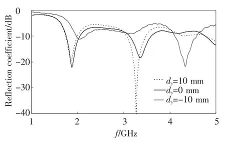
Fig.8 Influence of the loaded disc’s position on the reflection coefficient
From the simulation results,it can be seen that taking reflection coefficient as the optimization object,r=15 mm and dy=0 are finally attained as be the best combination.After obtaining the combination of r and dy,the antenna’s gain in the working bandwidth is simulated and then compared with the gain without the loaded disc,as shown in Fig.9.It can be seen that although the gain decreases somewhat(no more than 1.5 dB)with the loaded disc,the gain in band is more stable and with wider bandwidth.
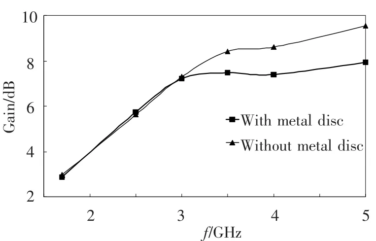
Fig.9 Influence of the disc on the antenna gain
3 Experimental Results
Prototype of the proposed antenna(as shown in Fig.10)are manufactured according to the acquired antenna parameters and measured in the anechoic chamber by using the Agilent E8363B vector network analyzer.The measuring content includes reflection coefficient,radiation pattern and gain,and the measurement results are presented in Figs.11 ~ 14.The experimental results show that the proposed antenna can operate well in the bandwidth of 1.6-5 GHz with reflection coefficient less than -6 dB,which is coincident with the simulation results;the measurement gain result is 1 dB smaller than the simulation result;the measurement and simulation results of the radiation pattern differ slightly in the main-lobe area,while they have many differences in the side-lobe.In general,the antenna property satisfies the technical index of ultrawideband antenna.The reasons for such differences can be explained as follows:(1)The printed substrate is normal FR-4 substrate which has large loss and the loss tangent is about 10-2order of magnitude,much larger than the common Rogers series materials(10-4order of magnitude).So the energy loss will result in the decrease of reflection coefficient and gain.(2)The measurement results of the side-lobe voltage level will be influenced by antenna weld and radiation-pattern test fixture.Besides,the instability of FR-4 substrate will also influence the measurement results of the antenna radiation pattern.

Fig.10 Prototype of the proposed antenna
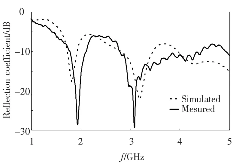
Fig.11 Measured results of reflection coefficient
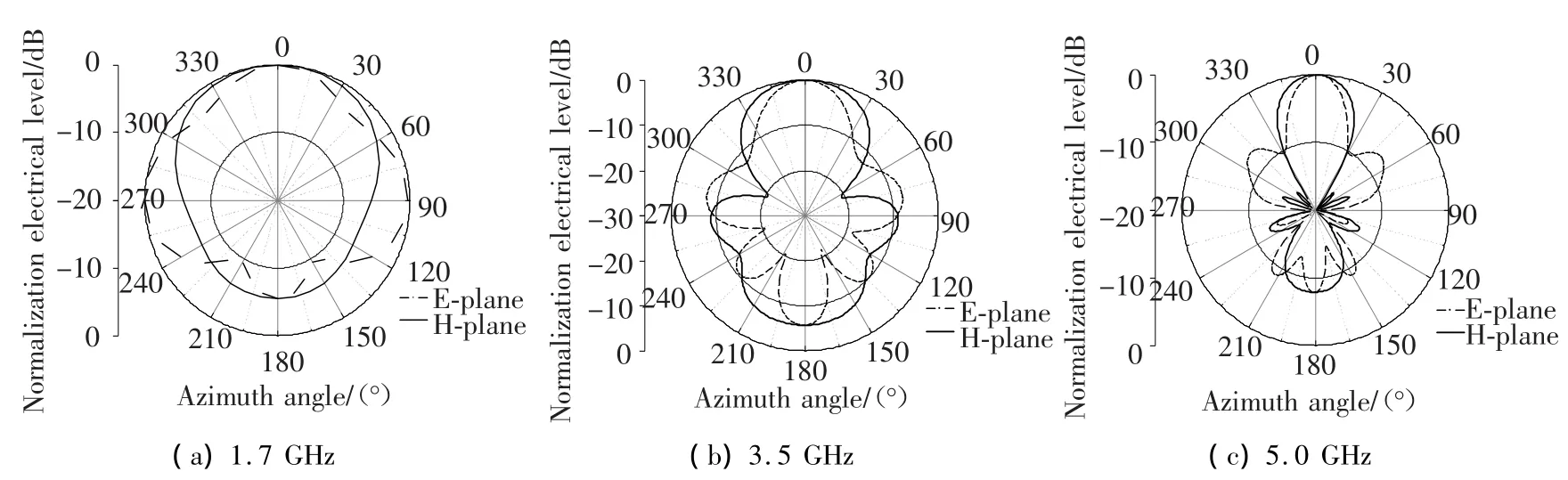
Fig.12 Simulated results of radiation pattern
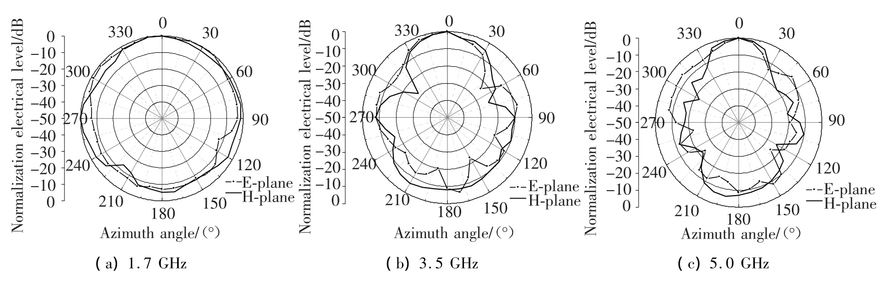
Fig.13 Measured results of radiation pattern
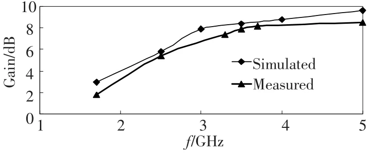
Fig.14 Antenna gain curve
4 Conclusions
A printed high-gain TEM horn antenna fed by balanced microstrip line is proposed.The surface current of the metal antenna is simulated and analyzed to explain the ultra-wideband characteristics of the antenna.Additionally,according to the simulation results of surface current on the metal radiator,the model of a dipole fed by balanced microstrip line independently with equal radiation characteristics to the TEM horn antenna is proposed to explain the directional radiation characteristics.The results also indicate that extending the length of the dielectric slab in the radiation direction has important effect on enhancing the antenna gain without influencing the antenna bandwidth,which illustrates a superior way to get a high antenna gain.Besides,loaded metal disc can make the gain in band more stable and is beneficial to increase gain bandwidth.The experiment results show that the antenna can operate at 1.64 to 5 GHz,and the typical antenna gain achieves 7 dB during the operating frequency which can be widely applied in the UWB field.What’s more,the balanced microstrip line method can avoid importing coaxial line,and in this way the application of this proposed antenna can be popularized in the millimeter-wave and the integrated circuit system field.
[1]Tajdini M M,Shahabadi M.Wideband planar log-periodic antenna.Conference Proceedings-2007 IEEE International Workshop on Antenna Technology:Small and Smart Antennas Metamaterials and Applications.Piscataway:IEEE.2007.331-334.
[2]Wang Baixiao,Chen Aixin.Design of an archimedean spiral antenna.The 8th International Symposium on Antennas,Propagation and EM Theory Proceedings.Beijing.2008.348-351.
[3]McFadden M,Scott W R.Analysis of the Equiangular Spiral Antenna on a Dielectric Substrate.IEEE Transactions on Antennas and Propagation,2007,55:3163 -3171.
[4]Tao Yonghui,Kan Shaohua,Wang Gang.Ultra-wideband bow-tie antenna design.2010 IEEE International Conference on Ultra-Wideband,2010,1:315 -317.
[5]Sun J S,Chen G Y.The tapered slot antenna.Microwave and Millimeter Wave Technology,2004.ICMMT 4th International Conference on,Proceedings.Taiwan.2004.1 -4.
[6]Lee R T,Smith G S.A design study for the basic TEM horn antenna.Antennas and Propagation Magazine,IEEE 2004.Piscataway:IEEE.2004.86-92.
[7]Catedra M F,Alcaraz J A,Arredondo J C.Analysis of arrays of Vivaldi and LTSA antennas.Antennas and Propagation Society International Symposium,1989,10:122 -125.
[8]Janaswmy R,Schaubert D H.Characteristic impedance of a wide slot line on low-permittivity substrates.IEEE Transactions on Microwave Theory and Techniques,1986,34(8):900-902.
猜你喜欢
疯狂英语·初中版(2022年7期)2022-07-11
少年文艺·我爱写作文(2022年4期)2022-05-12
Chinese Physics B(2022年4期)2022-04-12
作文评点报·低幼版(2020年42期)2020-12-14
陶瓷科学与艺术(2019年3期)2019-07-26
作文大王·低年级(2019年4期)2019-05-13
小资CHIC!ELEGANCE(2017年2期)2017-02-28
文艺生活·中旬刊(2016年5期)2016-10-21
Coco薇(2015年7期)2015-08-13
大众文艺(2015年24期)2015-07-13
 Journal of Harbin Institute of Technology(New Series)2012年6期
- Journal of Harbin Institute of Technology(New Series)的其它文章
- Load distribution of involute gears along time-varying contact line
- Spatially localized and joint access point selection for Wi-Fi indoor positioning
- Multiband printed monopole and dipole antenna with square-nested fractal
- Research on the Seebeck effect in efficient turning process and improving tool life
- A reliable and high throughput hybrid routing protocol for vehicular ad-hoc network
- An innovative detection method of high frequency BPSK signal with low signal-to-noise ratio